2006 DODGE RAM SRT-10 Crank pulley bolt
[x] Cancel search: Crank pulley boltPage 1411 of 5267
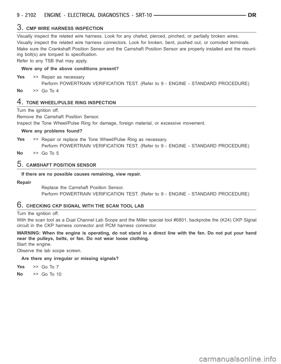
3.CMP WIRE HARNESS INSPECTION
Visually inspect the related wire harness. Look for any chafed, pierced, pinched, or partially broken wires.
Visually inspect the related wire harness connectors. Look for broken, bent, pushed out, or corroded terminals.
Make sure the Crankshaft Position Sensor and the Camshaft Position Sensorare properly installed and the mount-
ing bolt(s) are torqued to specification.
Refer to any TSB that may apply.
Were any of the above conditions present?
Ye s>>
Repair as necessary
Perform POWERTRAIN VERIFICATION TEST. (Refer to 9 - ENGINE - STANDARD PROCEDURE)
No>>
Go To 4
4.TONE WHEEL/PULSE RING INSPECTION
Turn the ignition off.
Remove the Camshaft Position Sensor.
Inspect the Tone Wheel/Pulse Ring for damage, foreign material, or excessive movement.
Were any problems found?
Ye s>>
Repair or replace the Tone Wheel/Pulse Ring as necessary.
Perform POWERTRAIN VERIFICATION TEST. (Refer to 9 - ENGINE - STANDARD PROCEDURE)
No>>
Go To 5
5.CAMSHAFT POSITION SENSOR
If there are no possible causes remaining, view repair.
Repair
Replace the Camshaft Position Sensor.
Perform POWERTRAIN VERIFICATION TEST. (Refer to 9 - ENGINE - STANDARD PROCEDURE)
6.CHECKING CKP SIGNAL WITH THE SCAN TOOL LAB
Turn the ignition off.
With the scan tool as a Dual Channel Lab Scope and the Miller special tool #6801, backprobe the (K24) CKP Signal
circuit in the CKP harness connector and PCM harness connector.
WARNING: When the engine is operating, do not stand in a direct line with thefan. Do not put your hand
near the pulleys, belts, or fan. Do not wear loose clothing.
Start the engine.
Observe the lab scope screen.
Are there any irregular or missing signals?
Ye s>>
Go To 7
No>>
Go To 10
Page 1412 of 5267
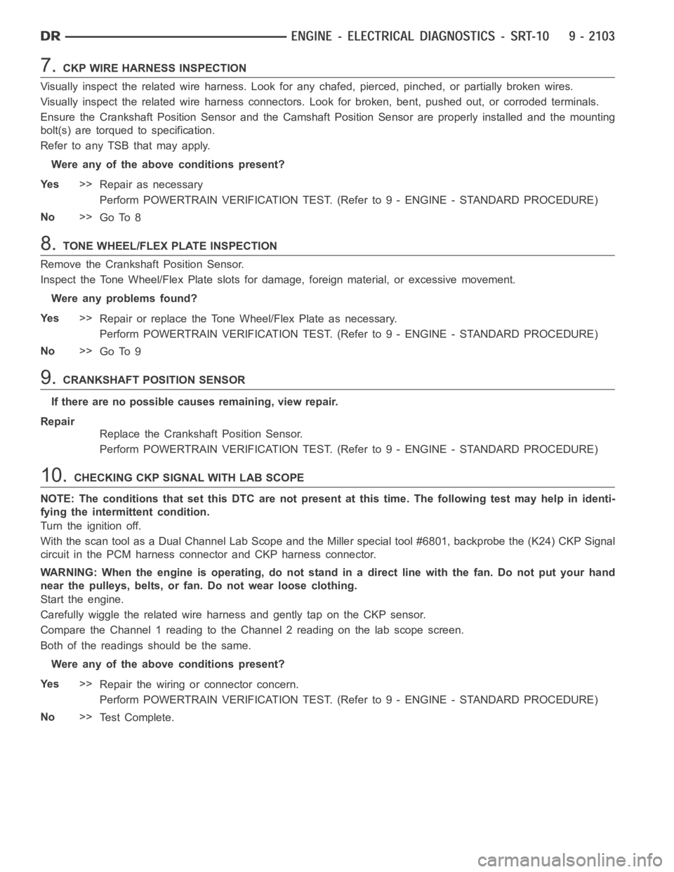
7.CKP WIRE HARNESS INSPECTION
Visually inspect the related wire harness. Look for any chafed, pierced, pinched, or partially broken wires.
Visually inspect the related wire harness connectors. Look for broken, bent, pushed out, or corroded terminals.
Ensure the Crankshaft Position Sensor and the Camshaft Position Sensor are properly installed and the mounting
bolt(s) are torqued to specification.
Refer to any TSB that may apply.
Were any of the above conditions present?
Ye s>>
Repair as necessary
Perform POWERTRAIN VERIFICATION TEST. (Refer to 9 - ENGINE - STANDARD PROCEDURE)
No>>
Go To 8
8.TONE WHEEL/FLEX PLATE INSPECTION
Remove the Crankshaft Position Sensor.
Inspect the Tone Wheel/Flex Plate slots for damage, foreign material, or excessive movement.
Were any problems found?
Ye s>>
Repair or replace the Tone Wheel/Flex Plate as necessary.
Perform POWERTRAIN VERIFICATION TEST. (Refer to 9 - ENGINE - STANDARD PROCEDURE)
No>>
Go To 9
9.CRANKSHAFT POSITION SENSOR
If there are no possible causes remaining, view repair.
Repair
Replace the Crankshaft Position Sensor.
Perform POWERTRAIN VERIFICATION TEST. (Refer to 9 - ENGINE - STANDARD PROCEDURE)
10.CHECKING CKP SIGNAL WITH LAB SCOPE
NOTE: The conditions that set this DTC are not present at this time. The following test may help in identi-
fying the intermittent condition.
Turn the ignition off.
With the scan tool as a Dual Channel Lab Scope and the Miller special tool #6801, backprobe the (K24) CKP Signal
circuit in the PCM harness connector and CKP harness connector.
WARNING: When the engine is operating, do not stand in a direct line with thefan. Do not put your hand
near the pulleys, belts, or fan. Do not wear loose clothing.
Start the engine.
Carefully wiggle the related wire harness and gently tap on the CKP sensor.
Compare the Channel 1 reading to the Channel 2 reading on the lab scope screen.
Both of the readings should be the same.
Were any of the above conditions present?
Ye s>>
Repair the wiring or connector concern.
Perform POWERTRAIN VERIFICATION TEST. (Refer to 9 - ENGINE - STANDARD PROCEDURE)
No>>
Te s t C o m p l e t e .
Page 1732 of 5267
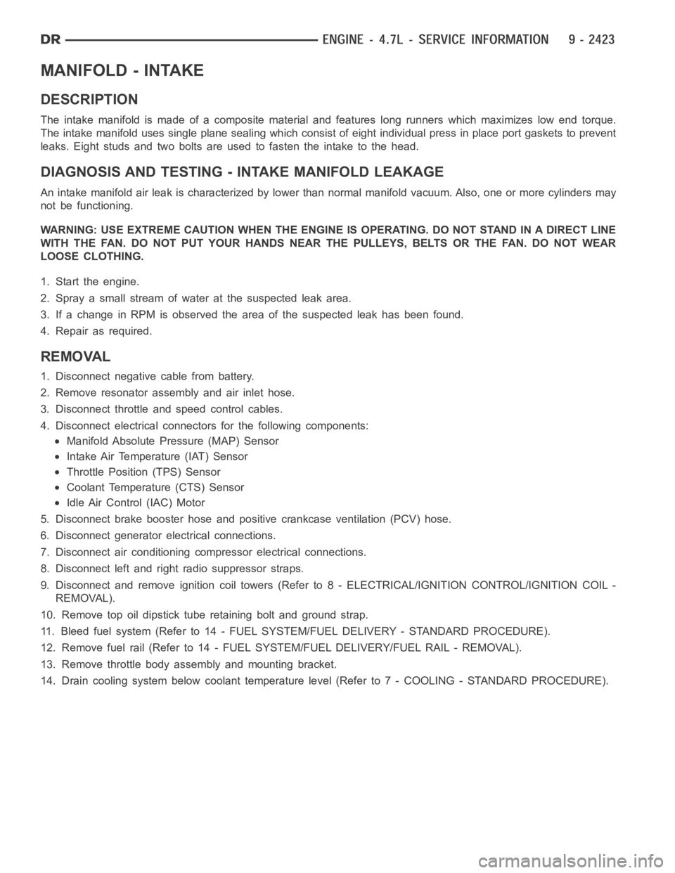
MANIFOLD - INTAKE
DESCRIPTION
The intake manifold is made of a composite material and features long runners which maximizes low end torque.
The intake manifold uses single plane sealing which consist of eight individual press in place port gaskets to prevent
leaks. Eight studs and two bolts are used to fasten the intake to the head.
DIAGNOSIS AND TESTING - INTAKE MANIFOLD LEAKAGE
An intake manifold air leak is characterized by lower than normal manifoldvacuum. Also, one or more cylinders may
not be functioning.
WARNING: USE EXTREME CAUTION WHEN THE ENGINE IS OPERATING. DO NOT STAND IN ADIRECT LINE
WITH THE FAN. DO NOT PUT YOUR HANDS NEAR THE PULLEYS, BELTS OR THE FAN. DO NOT WEAR
LOOSE CLOTHING.
1. Start the engine.
2. Spray a small stream of water at the suspected leak area.
3. If a change in RPM is observed the area of the suspected leak has been found.
4. Repair as required.
REMOVAL
1. Disconnect negative cable from battery.
2. Remove resonator assembly and air inlet hose.
3. Disconnect throttle and speed control cables.
4. Disconnect electrical connectors for the following components:
Manifold Absolute Pressure (MAP) Sensor
Intake Air Temperature (IAT) Sensor
Throttle Position (TPS) Sensor
Coolant Temperature (CTS) Sensor
Idle Air Control (IAC) Motor
5. Disconnect brake booster hose and positive crankcase ventilation (PCV)hose.
6. Disconnect generator electrical connections.
7. Disconnect air conditioning compressor electrical connections.
8. Disconnect left and right radio suppressor straps.
9. Disconnect and remove ignition coil towers (Refer to 8 - ELECTRICAL/IGNITION CONTROL/IGNITION COIL -
REMOVAL).
10. Remove top oil dipstick tube retaining bolt and ground strap.
11. Bleed fuel system (Refer to 14 - FUEL SYSTEM/FUEL DELIVERY - STANDARD PROCEDURE).
12. Remove fuel rail (Refer to 14 - FUEL SYSTEM/FUEL DELIVERY/FUEL RAIL - REMOVAL).
13. Remove throttle body assembly and mounting bracket.
14. Drain cooling system below coolant temperature level (Refer to 7 - COOLING - STANDARD PROCEDURE).
Page 1887 of 5267
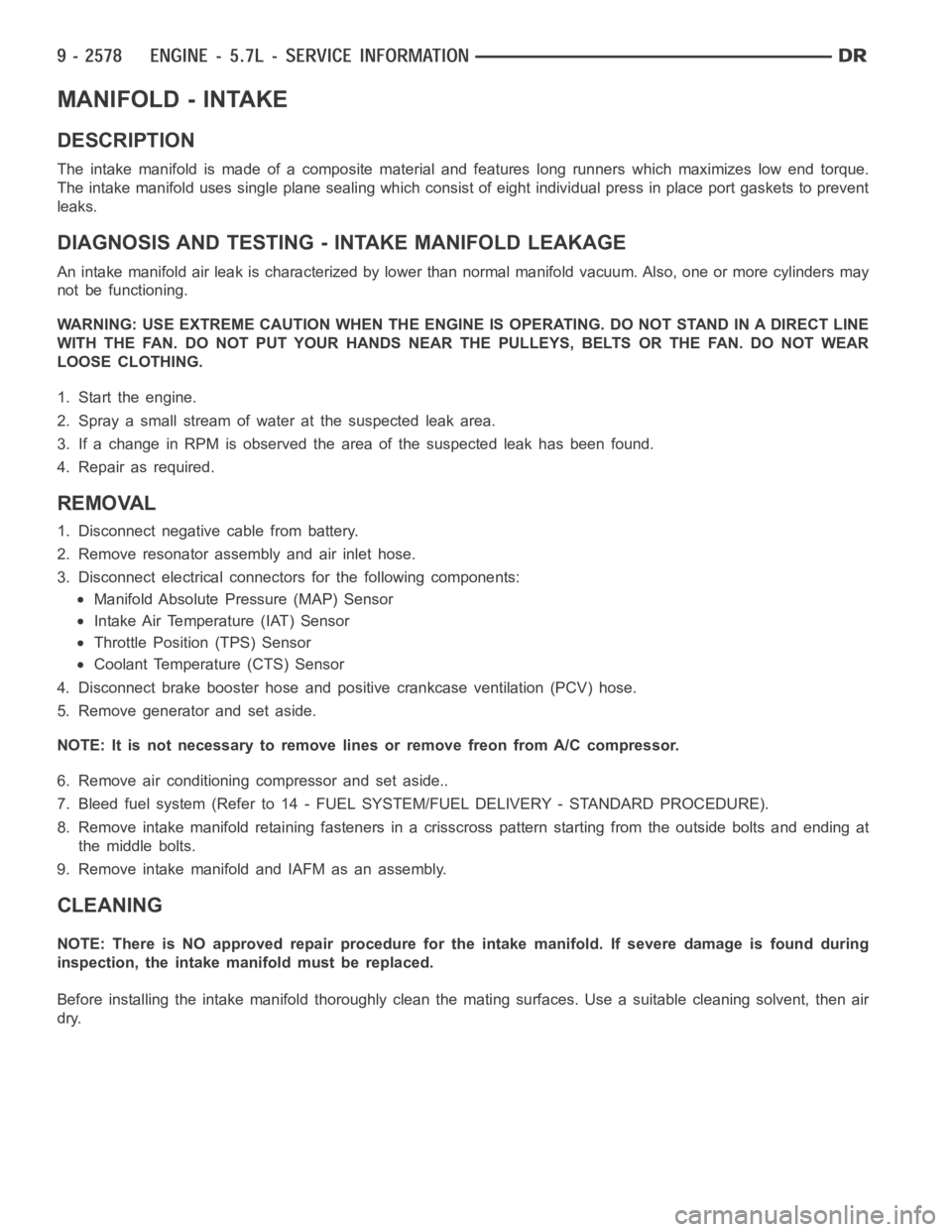
MANIFOLD - INTAKE
DESCRIPTION
The intake manifold is made of a composite material and features long runners which maximizes low end torque.
The intake manifold uses single plane sealing which consist of eight individual press in place port gaskets to prevent
leaks.
DIAGNOSIS AND TESTING - INTAKE MANIFOLD LEAKAGE
An intake manifold air leak is characterized by lower than normal manifoldvacuum. Also, one or more cylinders may
not be functioning.
WARNING: USE EXTREME CAUTION WHEN THE ENGINE IS OPERATING. DO NOT STAND IN ADIRECT LINE
WITH THE FAN. DO NOT PUT YOUR HANDS NEAR THE PULLEYS, BELTS OR THE FAN. DO NOT WEAR
LOOSE CLOTHING.
1. Start the engine.
2. Spray a small stream of water at the suspected leak area.
3. If a change in RPM is observed the area of the suspected leak has been found.
4. Repair as required.
REMOVAL
1. Disconnect negative cable from battery.
2. Remove resonator assembly and air inlet hose.
3. Disconnect electrical connectors for the following components:
Manifold Absolute Pressure (MAP) Sensor
Intake Air Temperature (IAT) Sensor
Throttle Position (TPS) Sensor
Coolant Temperature (CTS) Sensor
4. Disconnect brake booster hose and positive crankcase ventilation (PCV)hose.
5. Remove generator and set aside.
NOTE: It is not necessary to remove lines or remove freon from A/C compressor.
6. Remove air conditioning compressor and set aside..
7. Bleed fuel system (Refer to 14 - FUEL SYSTEM/FUEL DELIVERY - STANDARD PROCEDURE).
8. Remove intake manifold retaining fasteners in a crisscross pattern starting from the outside bolts and ending at
themiddlebolts.
9. Remove intake manifold and IAFM as an assembly.
CLEANING
NOTE: There is NO approved repair procedure for the intake manifold. If severe damage is found during
inspection, the intake manifold must be replaced.
Before installing the intake manifoldthoroughly clean the mating surfaces. Use a suitable cleaning solvent, then air
dry.
Page 1894 of 5267
INSTALLATION
1. Clean timing chain cover and block surface.
NOTE: Always install a new gasket on timing cover.
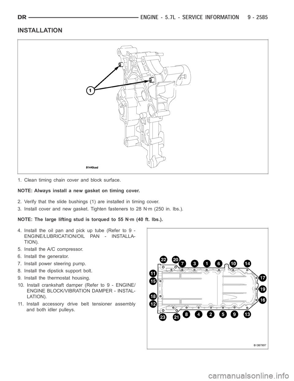
2. Verify that the slide bushings (1) are installed in timing cover.
3. Install cover and new gasket. Tighten fasteners to 28 Nꞏm (250 in. lbs.).
NOTE: The large lifting stud is torqued to 55 Nꞏm (40 ft. lbs.).
4. Install the oil pan and pick up tube (Refer to 9 -
ENGINE/LUBRICATION/OIL PAN - INSTALLA-
TION).
5. Install the A/C compressor.
6. Install the generator.
7. Install power steering pump.
8. Install the dipstick support bolt.
9. Install the thermostat housing.
10. Install crankshaft damper (Refer to 9 - ENGINE/
ENGINE BLOCK/VIBRATION DAMPER - INSTAL-
LATION).
11. Install accessory drive belt tensioner assembly
and both idler pulleys.
Page 2045 of 5267
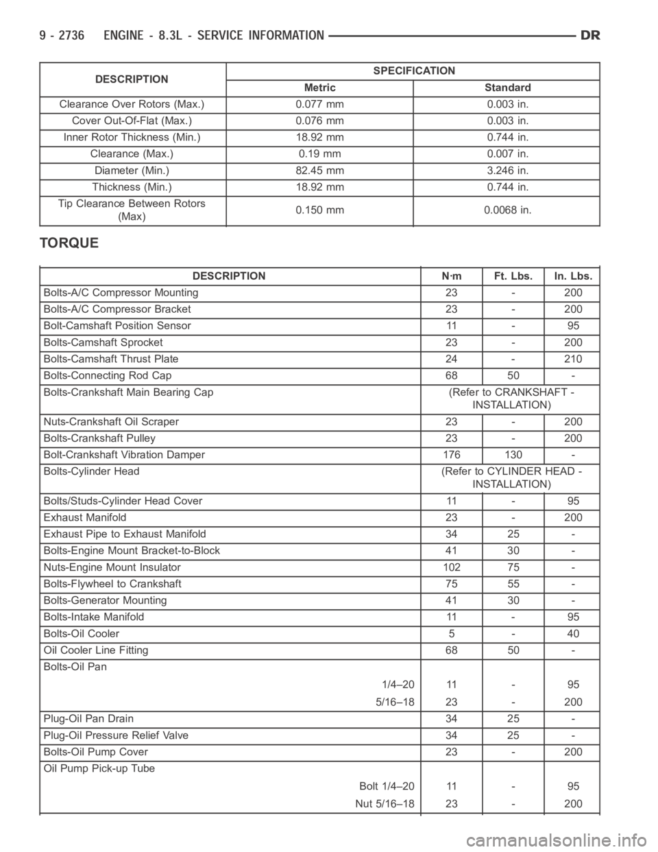
DESCRIPTIONSPECIFICATION
Metric Standard
Clearance Over Rotors (Max.) 0.077 mm 0.003 in.
Cover Out-Of-Flat (Max.) 0.076 mm 0.003 in.
Inner Rotor Thickness (Min.) 18.92 mm 0.744 in.
Clearance (Max.) 0.19 mm 0.007 in.
Diameter (Min.) 82.45 mm 3.246 in.
Thickness (Min.) 18.92 mm 0.744 in.
Tip Clearance Between Rotors
(Max)0.150 mm 0.0068 in.
TORQUE
DESCRIPTION Nꞏm Ft. Lbs. In. Lbs.
Bolts-A/C Compressor Mounting 23 - 200
Bolts-A/C Compressor Bracket 23 - 200
Bolt-Camshaft Position Sensor 11 - 95
Bolts-Camshaft Sprocket 23 - 200
Bolts-Camshaft Thrust Plate 24 - 210
Bolts-Connecting Rod Cap 68 50 -
Bolts-Crankshaft Main Bearing Cap (Refer to CRANKSHAFT -
INSTALLATION)
Nuts-Crankshaft Oil Scraper 23 - 200
Bolts-Crankshaft Pulley 23 - 200
Bolt-Crankshaft Vibration Damper 176 130 -
Bolts-Cylinder Head (Refer to CYLINDER HEAD -
INSTALLATION)
Bolts/Studs-Cylinder Head Cover 11 - 95
Exhaust Manifold 23 - 200
Exhaust Pipe to Exhaust Manifold 34 25 -
Bolts-Engine Mount Bracket-to-Block 41 30 -
Nuts-Engine Mount Insulator 102 75 -
Bolts-Flywheel to Crankshaft 75 55 -
Bolts-Generator Mounting 41 30 -
Bolts-Intake Manifold 11 - 95
Bolts-Oil Cooler 5 - 40
Oil Cooler Line Fitting 68 50 -
Bolts-Oil Pan
1/4–20 11 - 95
5/16–18 23 - 200
Plug-Oil Pan Drain 34 25 -
Plug-Oil Pressure Relief Valve 34 25 -
Bolts-Oil Pump Cover 23 - 200
Oil Pump Pick-up Tube
Bolt 1/4–20 11 - 95
Nut 5/16–18 23 - 200
Page 2080 of 5267
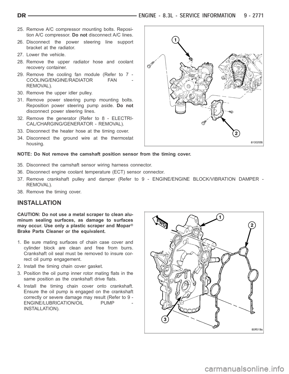
25. Remove A/C compressor mounting bolts. Reposi-
tion A/C compressor.Do notdisconnect A/C lines.
26. Disconnect the power steering line support
bracket at the radiator.
27. Lower the vehicle.
28. Remove the upper radiator hose and coolant
recovery container.
29. Remove the cooling fan module (Refer to 7 -
COOLING/ENGINE/RADIATOR FAN -
REMOVAL).
30. Remove the upper idler pulley.
31. Remove power steering pump mounting bolts.
Reposition power steering pump aside.Do not
disconnect power steering lines.
32. Remove the generator (Refer to 8 - ELECTRI-
CAL/CHARGING/GENERATOR - REMOVAL).
33. Disconnect the heater hose at the timing cover.
34. Disconnect the ground wire at the thermostat
housing.
NOTE: Do Not remove the camshaft position sensor from the timing cover.
35. Disconnect the camshaft sensor wiring harness connector.
36. Disconnect engine coolant temperature (ECT) sensor connector.
37. Remove crankshaft pulley and damper (Refer to 9 - ENGINE/ENGINE BLOCK/VIBRATION DAMPER -
REMOVAL).
38. Remove the timing cover.
INSTALLATION
CAUTION: Do not use a metal scraper to clean alu-
minum sealing surfaces, as damage to surfaces
may occur. Use only a plastic scraper and Mopar
Brake Parts Cleaner or the equivalent.
1. Be sure mating surfaces of chain case cover and
cylinder block are clean and free from burrs.
Crankshaft oil seal must be removed to insure cor-
rect oil pump engagement.
2. Install the timing chain cover gasket.
3. Position the oil pump inner rotor mating flats in the
same position as the crankshaft drive flats.
4. Install the timing chain cover onto crankshaft.
Ensure the oil pump is engaged on the crankshaft
correctly or severe damage may result (Refer to 9 -
ENGINE/LUBRICATION/OIL PUMP -
INSTALLATION).
Page 2081 of 5267

5. Hand start bolts No.1 and No.2.
6. Loosely install A/C compressor mounting bracket.
7. Hand start remaining timing chain cover bolts.
8. Torque timing chain cover bolts in the sequence
showninto23Nꞏm(200in.lbs.).
9. Torque A/C compressor mounting bracket bolts to
23 Nꞏm (200 in. lbs.).
10. Install crankshaft oil seal (Refer to 9 - ENGINE/
ENGINE BLOCK/CRANKSHAFT OIL SEAL -
FRONT - INSTALLATION).
11. Raise vehicle on hoist.
12. Install oil pump pick up tube using anewo-ring.
Torque 1/4–20 bolt to 11 Nꞏm (95 in. lbs.). Torque
5/16–18 nuts to 23 Nꞏm (200 in. lbs.).
13. Support the engine with a jack stand.
14. Install oil pan and drain plug (Refer to 9 -
ENGINE/LUBRICATION/OIL PAN - INSTALLA-
TION).
15. Remove the jackstand.
16. Tighten the engine mount to frame nuts to 102
Nꞏm (75 ft.lbs.).
17. Connect the oil cooler coolant hose to the timing
cover.
18. Connect the oil cooler line (Refer to 9 - ENGINE/
LUBRICATION/OIL COOLER & LINES - STAN-
DARD PROCEDURE).
19. Install the lower radiator hose.
20. Install the flywheel inspection cover.
21. Install the front frame cross member (Refer to 13
- FRAME & BUMPERS/FRAME/FRONT CROSS-
MEMBER - INSTALLATION).
22. Lower vehicle.
23. Position the compressor and install A/C compressor mounting bolts. Torque bolts to 23 Nꞏm (200 in. lbs.).
24. Connect heater hose at timing cover.
25. Install crankshaft damper and pulley (Refer to 9 - ENGINE/ENGINE BLOCK/VIBRATION DAMPER - INSTAL-
LATION).
26. Install generator. Connect electrical connectors.
27. Install the idler pulley.
28. Connect the camshaft position sensor wiring harness connector.
29. Connect engine coolant temperature (ECT) sensor wiring harness connector.
30. Install power steering pump mounting bolts.
31. Install accessory drive belt (Refer to 7 - COOLING/ACCESSORY DRIVE/DRIVE BELTS - INSTALLATION).
32. Install the radiator fan assembly (Refer to 7 - COOLING/ENGINE/RADIATOR FAN - INSTALLATION).