2006 DODGE RAM SRT-10 four wheel drive
[x] Cancel search: four wheel drivePage 1538 of 5267
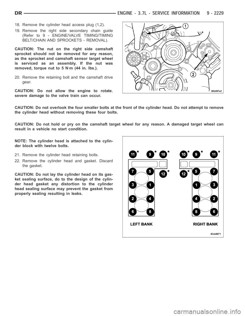
18. Remove the cylinder head access plug (1,2).
19. Remove the right side secondary chain guide
(Refer to 9 - ENGINE/VALVE TIMING/TIMING
BELT/CHAIN AND SPROCKETS - REMOVAL).
CAUTION: The nut on the right side camshaft
sprocket should not be removed for any reason,
as the sprocket and camshaft sensor target wheel
is serviced as an assembly. If the nut was
removed, torque nut to 5 Nꞏm (44 in. lbs.).
20. Remove the retaining bolt and the camshaft drive
gear.
CAUTION: Do not allow the engine to rotate.
severe damage to the valve train can occur.
CAUTION: Do not overlook the four smaller bolts at the front of the cylinderhead.Donotattempttoremove
the cylinder head without removing these four bolts.
CAUTION: Do not hold or pry on the camshaft target wheel for any reason. A damaged target wheel can
result in a vehicle no start condition.
NOTE: The cylinder head is attached to the cylin-
der block with twelve bolts.
21. Remove the cylinder head retaining bolts.
22. Remove the cylinder head and gasket. Discard
the gasket.
CAUTION: Do not lay the cylinder head on its gas-
ket sealing surface, do to the design of the cylin-
der head gasket any distortion to the cylinder
head sealing surface may prevent the gasket from
properly sealing resulting in leaks.
Page 1659 of 5267
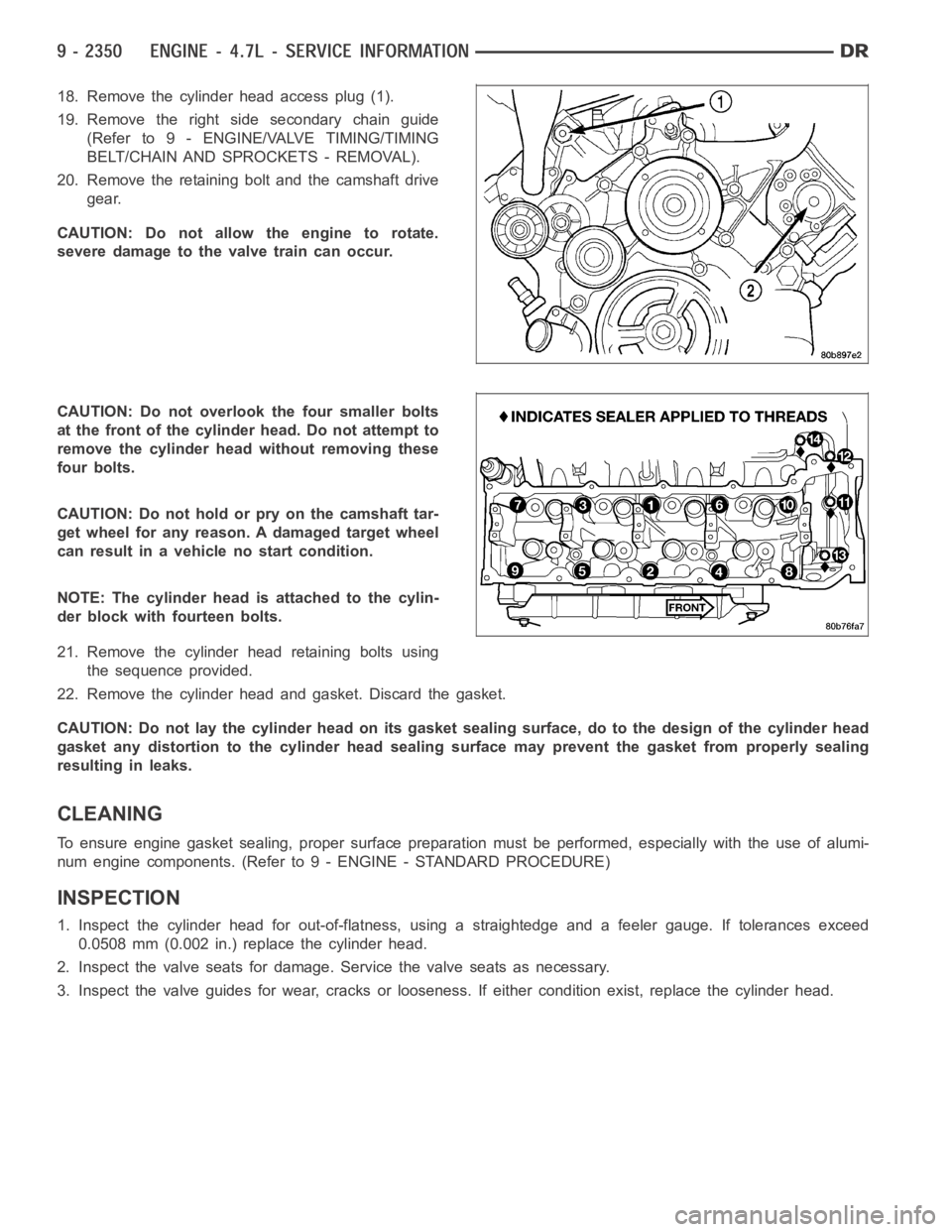
18. Remove the cylinder head access plug (1).
19. Remove the right side secondary chain guide
(Refer to 9 - ENGINE/VALVE TIMING/TIMING
BELT/CHAIN AND SPROCKETS - REMOVAL).
20. Remove the retaining bolt and the camshaft drive
gear.
CAUTION: Do not allow the engine to rotate.
severe damage to the valve train can occur.
CAUTION: Do not overlook the four smaller bolts
at the front of the cylinder head. Do not attempt to
remove the cylinder head without removing these
four bolts.
CAUTION: Do not hold or pry on the camshaft tar-
get wheel for any reason. A damaged target wheel
can result in a vehicle no start condition.
NOTE: The cylinder head is attached to the cylin-
der block with fourteen bolts.
21. Remove the cylinder head retaining bolts using
the sequence provided.
22. Remove the cylinder head and gasket. Discard the gasket.
CAUTION: Do not lay the cylinder head on its gasket sealing surface, do to the design of the cylinder head
gasket any distortion to the cylinder head sealing surface may prevent thegasket from properly sealing
resulting in leaks.
CLEANING
To ensure engine gasket sealing, proper surface preparation must be performed, especially with the use of alumi-
num engine components. (Refer to 9 - ENGINE - STANDARD PROCEDURE)
INSPECTION
1. Inspect the cylinder head for out-of-flatness, using a straightedge and a feeler gauge. If tolerances exceed
0.0508 mm (0.002 in.) replace the cylinder head.
2. Inspect the valve seats for damage. Service the valve seats as necessary.
3. Inspect the valve guides for wear, cracks or looseness. If either condition exist, replace the cylinder head.
Page 1980 of 5267
RETAINER - CRANK REAR OIL SEAL
REMOVAL
1. Disconnect the battery negative cables.
2. Raise vehicle on hoist.
3. Remove the oil pan drain plug and drain the engine
oil. Re-install plug and torque to 50 Nꞏm (44 ft. lbs.)
torque.
4. Remove transmission and transfer case (if
equipped) from vehicle.
5. Remove flywheel or torque converter drive plate.
6. Remove flywheel adapter plate.
7. Disconnect starter cables from starter motor.
8. Remove starter motor (Refer to 8 - ELECTRICAL/
STARTING/STARTER MOTOR - REMOVAL) and
transmission adapter plate assembly.
9. Remove four 4 oil pan rear bolts. Slide a feeler
gauge between the seal retainer and oil pan gasket
to break the seal.
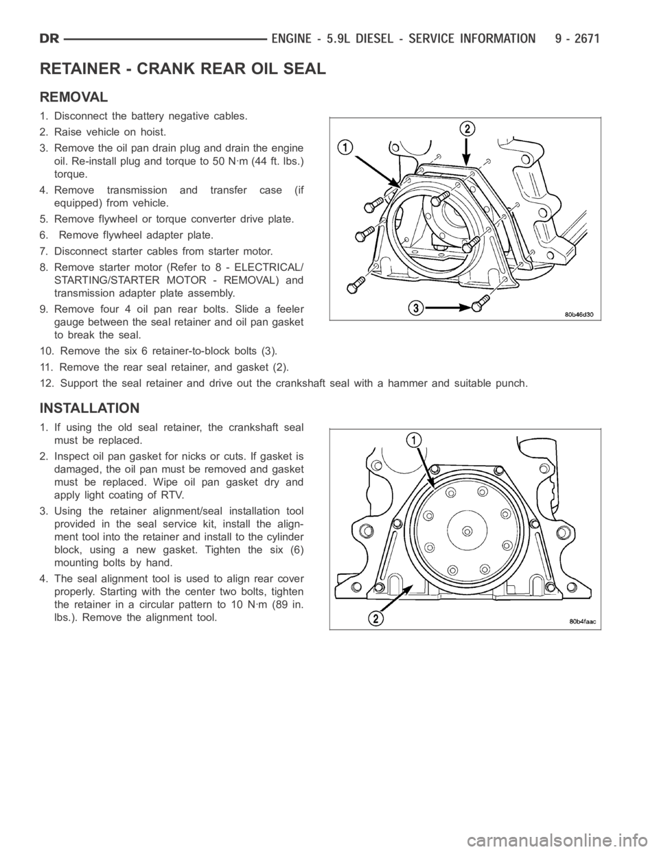
10. Remove the six 6 retainer-to-block bolts (3).
11. Remove the rear seal retainer, and gasket (2).
12. Support the seal retainer and drive out the crankshaft seal with a hammer and suitable punch.
INSTALLATION
1. If using the old seal retainer, the crankshaft seal
must be replaced.
2. Inspect oil pan gasket for nicks or cuts. If gasket is
damaged, the oil pan must be removed and gasket
must be replaced. Wipe oil pan gasket dry and
apply light coating of RTV.
3. Using the retainer alignment/seal installation tool
provided in the seal service kit, install the align-
ment tool into the retainer and install to the cylinder
block, using a new gasket. Tighten the six (6)
mounting bolts by hand.
4. The seal alignment tool is used to align rear cover
properly. Starting with the center two bolts, tighten
the retainer in a circular pattern to 10 Nꞏm (89 in.
lbs.). Remove the alignment tool.
Page 1981 of 5267
CAUTION: The seal lip and the sealing surface on
the crankshaft must be free from all oil residue to
prevent seal leaks. The crankshaft and seal sur-
faces must be completely dry when the seal is
installed. Use a soap and water solution on out-
side diameter of seal to ease assembly.
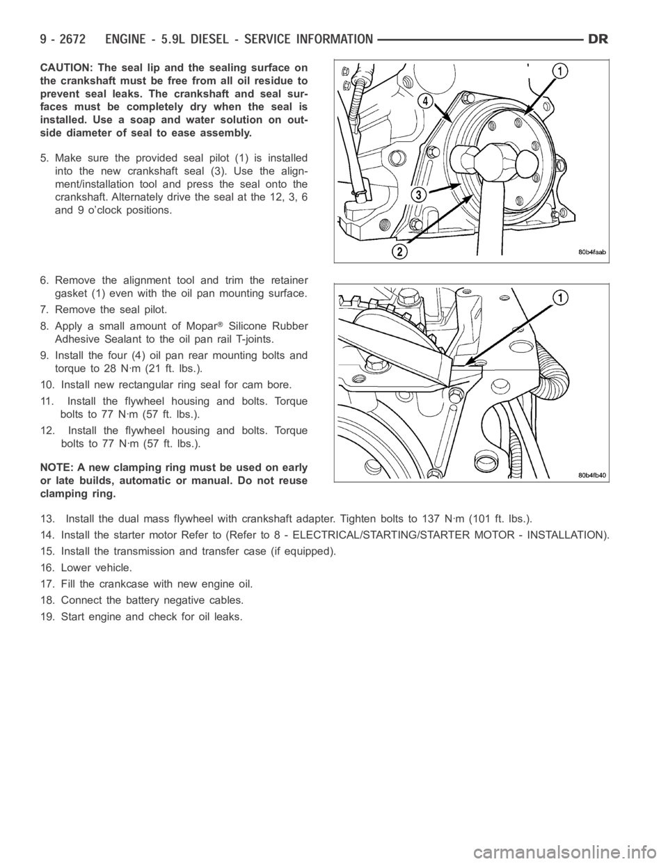
5. Make sure the provided seal pilot (1) is installed
into the new crankshaft seal (3). Use the align-
ment/installation tool and press the seal onto the
crankshaft. Alternately drive the seal at the 12, 3, 6
and 9 o’clock positions.
6. Remove the alignment tool and trim the retainer
gasket (1) even with the oil pan mounting surface.
7. Remove the seal pilot.
8. Apply a small amount of Mopar
Silicone Rubber
Adhesive Sealant to the oil pan rail T-joints.
9. Install the four (4) oil pan rear mounting bolts and
torque to 28 Nꞏm (21 ft. lbs.).
10. Install new rectangular ring seal for cam bore.
11. Install the flywheel housing and bolts. Torque
boltsto77Nꞏm(57ft.lbs.).
12. Install the flywheel housing and bolts. Torque
boltsto77Nꞏm(57ft.lbs.).
NOTE: A new clamping ring must be used on early
or late builds, automatic or manual. Do not reuse
clamping ring.
13. Install the dual mass flywheel with crankshaft adapter. Tighten boltsto 137 Nꞏm (101 ft. lbs.).
14. Install the starter motor Refer to (Refer to 8 - ELECTRICAL/STARTING/STA R T E R M O TO R - I N S TA L L AT I O N ) .
15. Install the transmission and transfer case (if equipped).
16. Lower vehicle.
17. Fill the crankcase with new engine oil.
18. Connect the battery negative cables.
19. Start engine and check for oil leaks.
Page 2921 of 5267
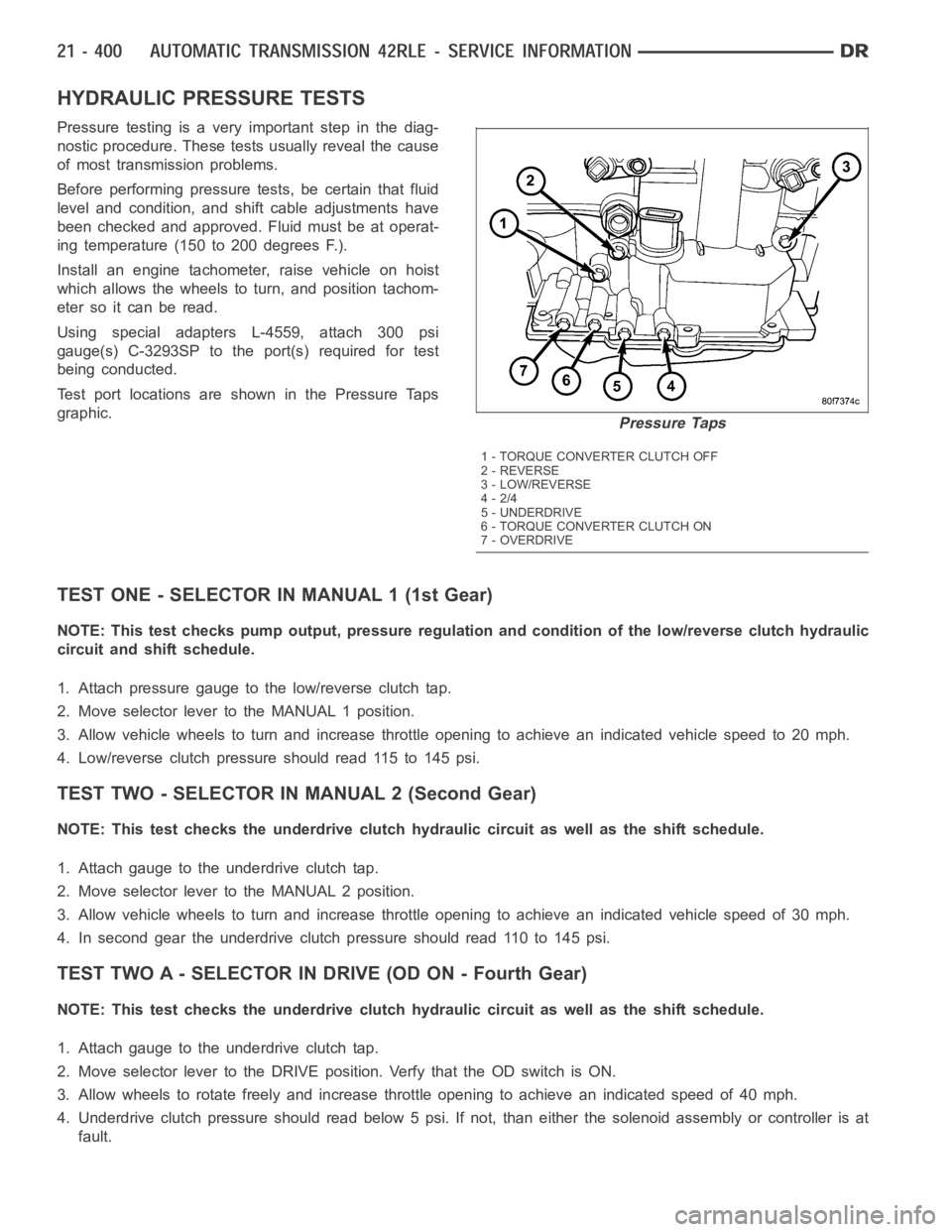
HYDRAULIC PRESSURE TESTS
Pressure testing is a very important step in the diag-
nostic procedure. These tests usually reveal the cause
of most transmission problems.
Before performing pressure tests, be certain that fluid
level and condition, and shift cable adjustments have
been checked and approved. Fluid must be at operat-
ing temperature (150 to 200 degrees F.).
Install an engine tachometer, raise vehicle on hoist
which allows the wheels to turn, and position tachom-
eter so it can be read.
Using special adapters L-4559, attach 300 psi
gauge(s) C-3293SP to the port(s) required for test
being conducted.
Test port locations are shown in the Pressure Taps
graphic.
TEST ONE - SELECTOR IN MANUAL 1 (1st Gear)
NOTE: This test checks pump output, pressure regulation and condition of the low/reverse clutch hydraulic
circuit and shift schedule.
1. Attach pressure gauge to the low/reverse clutch tap.
2. Move selector lever to the MANUAL 1 position.
3. Allow vehicle wheels to turn and increase throttle opening to achieve anindicatedvehiclespeedto20mph.
4. Low/reverse clutch pressure should read 115 to 145 psi.
TEST TWO - SELECTOR IN MANUAL 2 (Second Gear)
NOTE: This test checks the underdrive clutch hydraulic circuit as well as the shift schedule.
1. Attach gauge to the underdrive clutch tap.
2. Move selector lever to the MANUAL 2 position.
3. Allow vehicle wheels to turn and increase throttle opening to achieve anindicated vehicle speed of 30 mph.
4. In second gear the underdrive clutch pressure should read 110 to 145 psi.
TEST TWO A - SELECTOR IN DRIVE (OD ON - Fourth Gear)
NOTE: This test checks the underdrive clutch hydraulic circuit as well as the shift schedule.
1. Attach gauge to the underdrive clutch tap.
2. Move selector lever to the DRIVE position. Verfy that the OD switch is ON.
3. Allow wheels to rotate freely and increase throttle opening to achieve an indicated speed of 40 mph.
4. Underdrive clutch pressure should read below 5 psi. If not, than either the solenoid assembly or controller is at
fault.
Pressure Taps
1 - TORQUE CONVERTER CLUTCH OFF
2 - REVERSE
3 - LOW/REVERSE
4-2/4
5 - UNDERDRIVE
6 - TORQUE CONVERTER CLUTCH ON
7-OVERDRIVE
Page 2922 of 5267
TEST THREE - SELECTOR IN DRIVE (OD OFF - Third and Second Gear)
NOTE: This test checks the overdrive clutch hydraulic circuit as well as the shift schedule.
1. Attach gauge to the overdrive clutch tap.
2. Move selector lever to the DRIVE position.
3. Allow vehicle wheels to turn and increase throttle opening to achieve anindicated vehicle speed of 20 mph.
4. Overdrive clutch pressure should read 74 to 95 psi.
5. Move selector lever to the DRIVE position and increase indicated vehicle speed to 30 mph.
6. The vehicle should be in second gearand overdrive clutch pressure shouldbelessthan5psi.
TEST FOUR - SELECTOR IN DRIVE (OD ON - Fourth Gear)
NOTE: This test checks the 2/4 clutch hydraulic circuit.
1. Attach gauge to the 2/4 clutch tap.
2. Move selector lever to the DRIVE position.
3. Allow vehicle front wheels to turn and increase throttle opening to achieve an indicated vehicle speed of 30 mph.
Vehicleshouldbeinfourthgear.
4. The 2/4 clutch pressure should read 75 to 95 psi.
TEST FIVE-SELECTOR IN DRIVE (OD ON - Fourth Gear, CC on)
NOTE: These tests check the torque converter clutch hydraulic circuit.
1. Attach gauge to the torque converter clutch off pressure tap.
2. Move selector lever to the DRIVE position.
3. Allow vehicle wheels to turn and increase throttle opening to achieve anindicated vehicle speed of 50 mph.
Vehicle should be in 4th gear, CC on.
CAUTION: Both wheels must turn at the same speed.
4. Torque converter clutch off pressure should be less than 5 psi.
5. Now attach the gauge to the torque converter clutch on pressure tap.
6. Move selector to the OD position.
7. Allow vehicle wheels to turn and increase throttle opening to achieve anindicated vehicle speed of 50 mph.
8. Verify the torque converter clutch is applied mode using the RPM displayof the scan tool.
9. Torque converter clutch on pressure should be 60-90 psi.
TEST SIX-SELECTOR IN REVERSE
NOTE: This test checks the reverse clutch hydraulic circuit.
1. Attach gauge to the reverse and low/reverse clutch tap.
2. Move selector lever to the REVERSE position.
3. Read reverse clutch pressure with output stationary (foot on brake) andthrottle opened to achieve 1500 rpm.
4. Reverse and low/reverse clutch pressure should read 165 to 235 psi.
TEST RESULT INDICATIONS
1. If proper line pressure is found in any one test, the pump and pressure regulator are working properly.
2. Low pressure in all positions indicates a defective pump, a clogged filter, or a stuck pressure regulator valve.
3. Clutch circuit leaks are indicated if pressures do not fall within the specified pressure range.
4. If the overdrive clutch pressure is greater than 5 psi in Step 6 of Test Three, a worn reaction shaft seal ring or
a defective solenoid assembly is indicated.
Page 3069 of 5267
TORQUE CONVERTER CLUTCH (TCC)
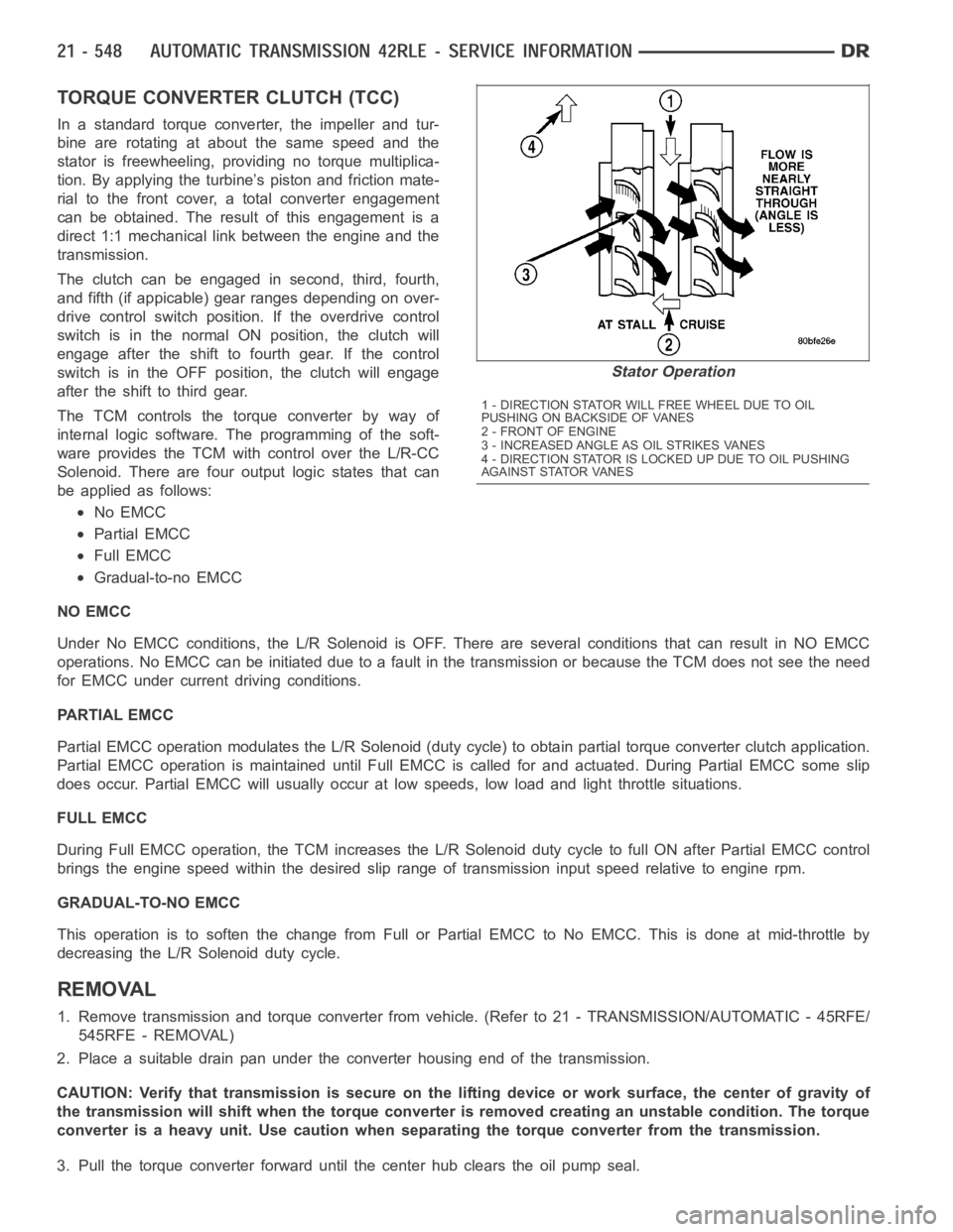
In a standard torque converter, the impeller and tur-
bine are rotating at about the same speed and the
stator is freewheeling, providing no torque multiplica-
tion. By applying the turbine’s piston and friction mate-
rial to the front cover, a total converter engagement
can be obtained. The result of this engagement is a
direct 1:1 mechanical link between the engine and the
transmission.
The clutch can be engaged in second, third, fourth,
and fifth (if appicable) gear ranges depending on over-
drive control switch position. If the overdrive control
switch is in the normal ON position, the clutch will
engage after the shift to fourth gear. If the control
switch is in the OFF position, the clutch will engage
after the shift to third gear.
The TCM controls the torque converter by way of
internal logic software. The programming of the soft-
ware provides the TCM with control over the L/R-CC
Solenoid. There are four output logic states that can
be applied as follows:
No EMCC
Partial EMCC
Full EMCC
Gradual-to-no EMCC
NO EMCC
Under No EMCC conditions, the L/R Solenoid is OFF. There are several conditions that can result in NO EMCC
operations. No EMCC can be initiated due to a fault in the transmission or because the TCM does not see the need
for EMCC under current driving conditions.
PARTIAL EMCC
Partial EMCC operation modulates the L/R Solenoid (duty cycle) to obtain partial torque converter clutch application.
Partial EMCC operation is maintaineduntil Full EMCC is called for and actuated. During Partial EMCC some slip
does occur. Partial EMCC will usually occur at low speeds, low load and light throttle situations.
FULL EMCC
During Full EMCC operation, the TCM increases the L/R Solenoid duty cycle to full ON after Partial EMCC control
brings the engine speed within the desired slip range of transmission input speed relative to engine rpm.
GRADUAL-TO-NO EMCC
This operation is to soften the change from Full or Partial EMCC to No EMCC. This is done at mid-throttle by
decreasing the L/R Solenoid duty cycle.
REMOVAL
1. Remove transmission and torque converter from vehicle. (Refer to 21 - TRANSMISSION/AUTOMATIC - 45RFE/
545RFE - REMOVAL)
2. Place a suitable drain pan under the converter housing end of the transmission.
CAUTION: Verify that transmission is secure on the lifting device or work surface, the center of gravity of
the transmission will shift when the torque converter is removed creatingan unstable condition. The torque
converter is a heavy unit. Use caution when separating the torque converter from the transmission.
3. Pull the torque converter forward until the center hub clears the oil pumpseal.
Stator Operation
1 - DIRECTION STATOR WILL FREE WHEEL DUE TO OIL
PUSHING ON BACKSIDE OF VANES
2-FRONTOFENGINE
3 - INCREASED ANGLE AS OIL STRIKES VANES
4 - DIRECTION STATOR IS LOCKED UP DUE TO OIL PUSHING
AGAINST STATOR VANES
Page 3487 of 5267
TORQUE CONVERTER CLUTCH (TCC)
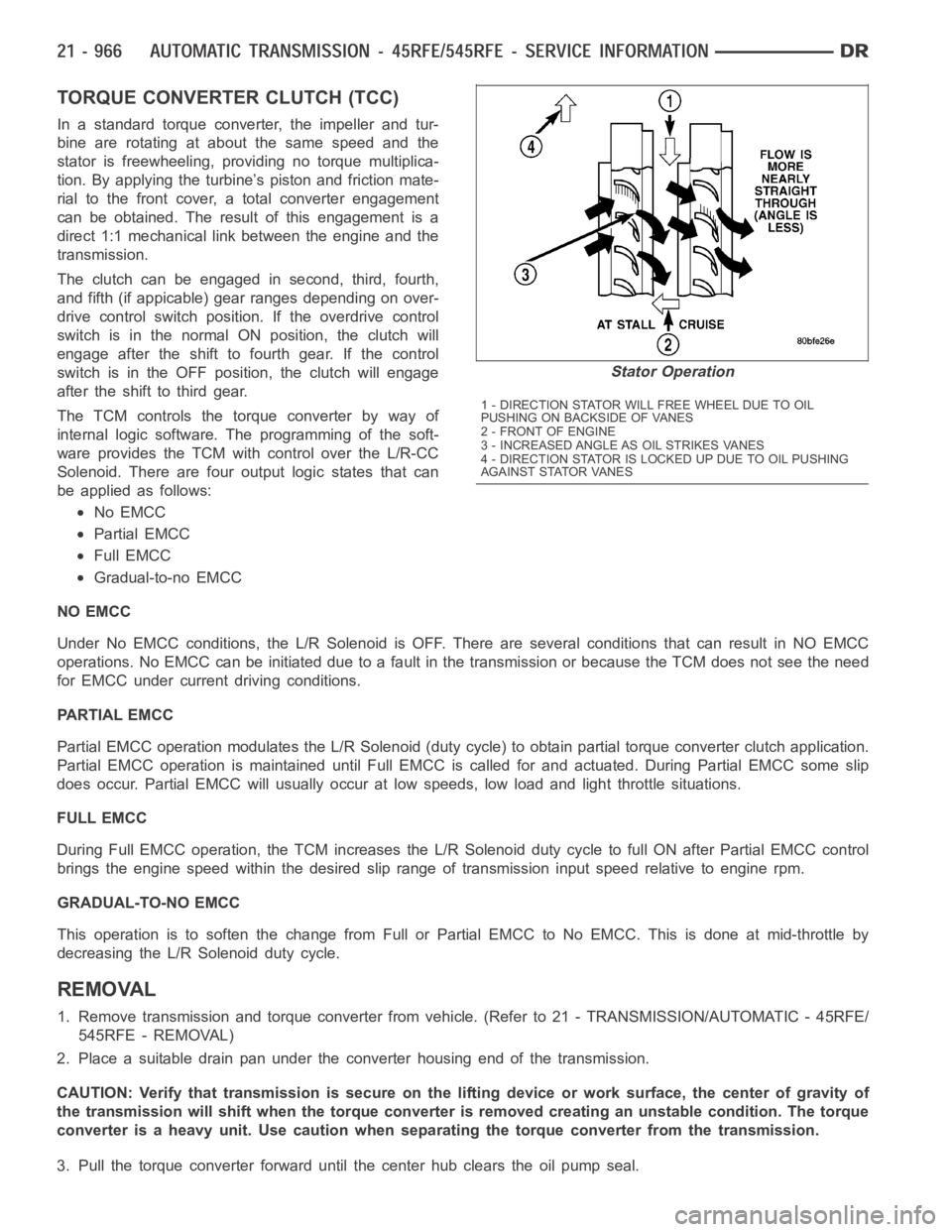
In a standard torque converter, the impeller and tur-
bine are rotating at about the same speed and the
stator is freewheeling, providing no torque multiplica-
tion. By applying the turbine’s piston and friction mate-
rial to the front cover, a total converter engagement
can be obtained. The result of this engagement is a
direct 1:1 mechanical link between the engine and the
transmission.
The clutch can be engaged in second, third, fourth,
and fifth (if appicable) gear ranges depending on over-
drive control switch position. If the overdrive control
switch is in the normal ON position, the clutch will
engage after the shift to fourth gear. If the control
switch is in the OFF position, the clutch will engage
after the shift to third gear.
The TCM controls the torque converter by way of
internal logic software. The programming of the soft-
ware provides the TCM with control over the L/R-CC
Solenoid. There are four output logic states that can
be applied as follows:
No EMCC
Partial EMCC
Full EMCC
Gradual-to-no EMCC
NO EMCC
Under No EMCC conditions, the L/R Solenoid is OFF. There are several conditions that can result in NO EMCC
operations. No EMCC can be initiated due to a fault in the transmission or because the TCM does not see the need
for EMCC under current driving conditions.
PARTIAL EMCC
Partial EMCC operation modulates the L/R Solenoid (duty cycle) to obtain partial torque converter clutch application.
Partial EMCC operation is maintaineduntil Full EMCC is called for and actuated. During Partial EMCC some slip
does occur. Partial EMCC will usually occur at low speeds, low load and light throttle situations.
FULL EMCC
During Full EMCC operation, the TCM increases the L/R Solenoid duty cycle to full ON after Partial EMCC control
brings the engine speed within the desired slip range of transmission input speed relative to engine rpm.
GRADUAL-TO-NO EMCC
This operation is to soften the change from Full or Partial EMCC to No EMCC. This is done at mid-throttle by
decreasing the L/R Solenoid duty cycle.
REMOVAL
1. Remove transmission and torque converter from vehicle. (Refer to 21 - TRANSMISSION/AUTOMATIC - 45RFE/
545RFE - REMOVAL)
2. Place a suitable drain pan under the converter housing end of the transmission.
CAUTION: Verify that transmission is secure on the lifting device or work surface, the center of gravity of
the transmission will shift when the torque converter is removed creatingan unstable condition. The torque
converter is a heavy unit. Use caution when separating the torque converter from the transmission.
3. Pull the torque converter forward until the center hub clears the oil pumpseal.
Stator Operation
1 - DIRECTION STATOR WILL FREE WHEEL DUE TO OIL
PUSHING ON BACKSIDE OF VANES
2-FRONTOFENGINE
3 - INCREASED ANGLE AS OIL STRIKES VANES
4 - DIRECTION STATOR IS LOCKED UP DUE TO OIL PUSHING
AGAINST STATOR VANES