2006 DODGE RAM SRT-10 four wheel drive
[x] Cancel search: four wheel drivePage 3797 of 5267
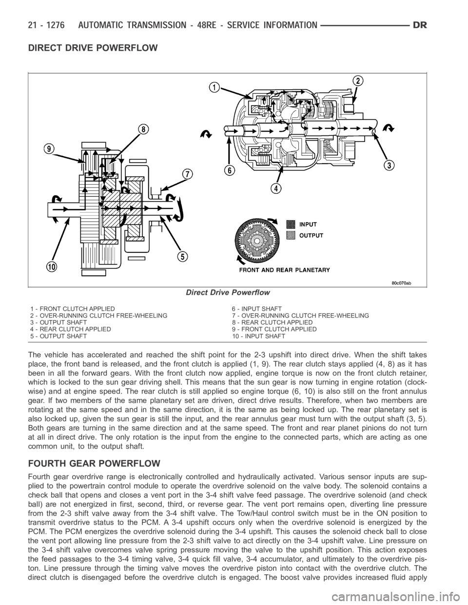
DIRECT DRIVE POWERFLOW
The vehicle has accelerated and reached the shift point for the 2-3 upshiftinto direct drive. When the shift takes
place, the front band is released, and the front clutch is applied (1, 9). The rear clutch stays applied (4, 8) as it has
been in all the forward gears. With the front clutch now applied, engine torque is now on the front clutch retainer,
which is locked to the sun gear drivingshell. This means that the sun gear isnow turning in engine rotation (clock-
wise) and at engine speed. The rear clutch is still applied so engine torque(6, 10) is also still on the front annulus
gear. If two members of the same planetary set are driven, direct drive results. Therefore, when two members are
rotating at the same speed and in the same direction, it is the same as being locked up. The rear planetary set is
also locked up, given the sun gear is still the input, and the rear annulus gear must turn with the output shaft (3, 5).
Both gears are turning in the same direction and at the same speed. The frontand rear planet pinions do not turn
at all in direct drive. The only rotation is the input from the engine to the connected parts, which are acting as one
common unit, to the output shaft.
FOURTHGEARPOWERFLOW
Fourth gear overdrive range is electronically controlled and hydraulically activated. Various sensor inputs are sup-
plied to the powertrain control module to operate the overdrive solenoid on the valve body. The solenoid contains a
check ball that opens and closes a vent port in the 3-4 shift valve feed passage. The overdrive solenoid (and check
ball) are not energized in first, second, third, or reverse gear. The vent port remains open, diverting line pressure
from the 2-3 shift valve away from the 3-4 shift valve. The Tow/Haul controlswitch must be in the ON position to
transmit overdrive status to the PCM. A 3-4 upshift occurs only when the overdrive solenoid is energized by the
PCM. The PCM energizes the overdrive solenoid during the 3-4 upshift. Thiscauses the solenoid check ball to close
the vent port allowing line pressure from the 2-3 shift valve to act directly on the 3-4 upshift valve. Line pressure on
the 3-4 shift valve overcomes valve spring pressure moving the valve to theupshift position. This action exposes
the feed passages to the 3-4 timing valve, 3-4 quick fill valve, 3-4 accumulator, and ultimately to the overdrive pis-
ton. Line pressure through the timing valve moves the overdrive piston into contact with the overdrive clutch. The
direct clutch is disengaged before the overdrive clutch is engaged. The boost valve provides increased fluid apply
Direct Drive Powerflow
1 - FRONT CLUTCH APPLIED 6 - INPUT SHAFT
2 - OVER-RUNNING CLUTCH FREE-WHEELING 7 - OVER-RUNNING CLUTCH FREE-WHEELING
3 - OUTPUT SHAFT 8 - REAR CLUTCH APPLIED
4 - REAR CLUTCH APPLIED 9 - FRONT CLUTCH APPLIED
5 - OUTPUT SHAFT 10 - INPUT SHAFT
Page 3798 of 5267
pressure to the overdrive clutch during 3-4 upshifts, and when accelerating in fourth gear. The 3-4 accumulator
cushions overdrive clutch engagement to smooth 3-4 upshifts. The accumulator is charged at the same time as
apply pressure acts against the overdrive piston.
DIAGNOSIS AND TESTING
AUTOMATIC TRANSMISSION
Automatic transmission problems can be a result of poor engine performance, incorrect fluid level, incorrect linkage
or cable adjustment, band or hydraulic control pressure adjustments, hydraulic system malfunctions or electrical/
mechanical component malfunctions. Begin diagnosis by checking the easily accessible items such as: fluid level
and condition, linkage adjustments and electrical connections. A road test will determine if further diagnosis is nec-
essary.
PRELIMINARY
Two basic procedures are required. One procedure for vehicles that are drivable and an alternate procedure for
disabled vehicles (will not back up or move forward).
VEHICLE IS DRIVEABLE
1. Check for transmission fault codes using DRBscan tool.
2. Check fluid level and condition.
3. Adjust throttle and gearshift linkage if complaint was based on delayed, erratic, or harsh shifts.
4. Road test and note how transmission upshifts, downshifts, and engages.
5. Perform hydraulic pressure test if shift problems were noted during roadtest.
6. Perform air-pressure test to check clutch-band operation.
VEHICLE IS DISABLED
1. Check fluid level and condition.
2. Check for broken or disconnected gearshift or throttle linkage.
3. Check for cracked, leaking cooler lines, or loose or missing pressure-port plugs.
4. Raise and support vehicle on safety stands, start engine, shift transmission into gear, and note following:
a. If propeller shaft turns but wheels do not, problem is with differentialor axle shafts.
b. If propeller shaft does not turn and transmission is noisy, stop engine.Remove oil pan, and check for debris.
If pan is clear, remove transmission and check for damaged drive plate, converter, oil pump, or input shaft.
c. If propeller shaft does not turn and transmission is not noisy, perform hydraulic-pressure test to determine if
problem is hydraulic or mechanical.
ROAD TESTING
Before road testing, be sure the fluid level and control cable adjustmentshave been checked and adjusted if nec-
essary. Verify that diagnostic trouble codes have been resolved.
Observe engine performance during the road test. A poorly tuned engine will not allow accurate analysis of trans-
mission operation.
Operate the transmission in all gear ranges. Check for shift variations and engine flare which indicates slippage.
Note if shifts are harsh, spongy, delayed, early, or if part throttle downshifts are sensitive.
Slippage indicated by engine flare, usually means clutch, band or overrunning clutch problems. If the condition is
advanced, an overhaul will be necessary to restore normal operation.
A slipping clutch or band can often be determined by comparing which internal units are applied in the various gear
ranges. The Clutch and Band Application chart provides a basis for analyzing road test results.
Clutch and Band Application Chart
Page 3801 of 5267
5. Line pressure should be 54-60 psi (372-414 kPa) with throttle lever forward and gradually increase to 90-96 psi
(621-662 kPa) as lever is moved rearward.
Test Three - Transmission In D Range Third Gear
This test checks pressure regulation and condition of the clutch circuits. Both test gauges are required for this test.
1. Turn OD switch off.
2. Leave vehicle on hoist and leave Oil Pressure Gauge C-3292 in place at accumulator port.
3. Move Oil Pressure Gauge C-3293-SP over to front servo port for this test.
4. Have helper start and run engine at 1600 rpm for this test.
5. Move transmission shift lever two detents rearward from full forward position. This is D range.
6. Read pressures on both gauges as transmission throttle lever is gradually moved from full forward to full rear-
ward position:
Line pressure at accumulator in D range third gear, should be 54-60 psi (372-414 kPa) with throttle lever for-
ward and increase as lever is moved rearward.
Front servo pressure in D range third gear, should be within 3 psi (21 kPa) ofline pressure up to kickdown
point.
Test Four - Transmission In Reverse
This test checks pump output, pressure regulation and the front clutch andrear servo circuits. Use 300 psi Oil
Pressure Gauge C-3293-SP for this test.
1. Leave vehicle on hoist and leave Oil Pressure Gauge C-3292 in place at accumulator port.
2. Move 300 psi Oil Pressure Gauge C-3293-SP back to rear servo port.
3. Have helper start and run engine at 1600 rpm for test.
4. Move transmission shift lever four detents rearward from full forward position. This is Reverse range.
5. Move transmission throttle lever fully forward then fully rearward andnote reading at Gauge C-3293-SP.
6. Pressure should be 145 - 175 psi (1000-1207 kPa) with throttle lever forward and increase to 230 - 280 psi
(1586-1931 kPa) as lever is gradually moved rearward.
Test Five - Governor Pressure
This test checks governor operation by measuring governor pressure response to changes in vehicle speed. It is
usually not necessary to check governor operation unless shift speeds areincorrect or if the transmission will not
downshift. The test should be performed on the road or on a hoist that will allow the rear wheels to rotate freely.
1. Move 100 psi Oil Pressure Gauge C-3292 to governor pressure port.
2. Move transmission shift lever two detents rearward from full forward position. This is D range.
3. Have helper start and run engine at curb idle speed. Then firmly apply service brakes so wheels will not rotate.
4. Note governor pressure:
Governor pressure should be no more than 20.6 kPa (3 psi) at curb idle speed and wheels not rotating.
If pressure exceeds 20.6 kPa (3 psi), a fault exists in governor pressure control system.
5. Release brakes, slowly increase engine speed, and observe speedometerand pressure test gauge (do not
exceed 30 mph on speedometer). Governor pressure should increase in proportion to vehicle speed. Or approx-
imately 6.89 kPa (1 psi) for every 1 mph.
6. Governor pressure rise should be smooth and drop back to no more than 20.6kPa (3 psi), after engine returns
to curb idle and brakes are applied to prevent wheels from rotating.
7. Compare results of pressure test with analysis chart.
Test Six - Transmission In Overdrive Fourth Gear
This test checks line pressure at the overdrive clutch in fourth gear range. Use 300 psi Oil Pressure Gauge
C-3293-SP for this test. The test should be performed on the road or on a chassis dyno.
1. Remove tachometer; it is not needed for this test.
2. Move 300 psi Oil Pressure Gauge to overdrive clutch pressure test port. Then remove other gauge and reinstall
test port plug.
Page 3870 of 5267
WIDE OPEN THROTTLE OPERATION
In wide-open throttle (WOT) mode, adaptive memory in the PCM assures that up-shifts occur at the preprogrammed
optimum speed. WOT operation is determined from the throttle position sensor, which is also a part of the emission
control system. The initial setting for the WOT upshift is below the optimum engine speed. As WOT shifts are
repeated, the PCM learns the time required to complete the shifts by comparing the engine speed when the shifts
occur to the optimum speed. After each shift, the PCM adjusts the shift point until the optimum speed is reached.
The PCM also considers vehicle loading, grade and engine performance changes due to high altitude in determining
when to make WOT shifts. It does this by measuring vehicle and engine acceleration and then factoring in the shift
time.
TRANSFER CASE LOW RANGE OPERATION
On four-wheel drive vehicles operating in low range, the engine can accelerate to its peak more rapidly than in
Normal range, resulting in delayed shifts and undesirable engine
flare.The low range governor pressure curve is
also higher than normal to initiate upshifts sooner. The PCM compares electronic vehicle speed signal used by the
speedometer to the transmission output shaft speed signal to determine when the transfer case is in low range.
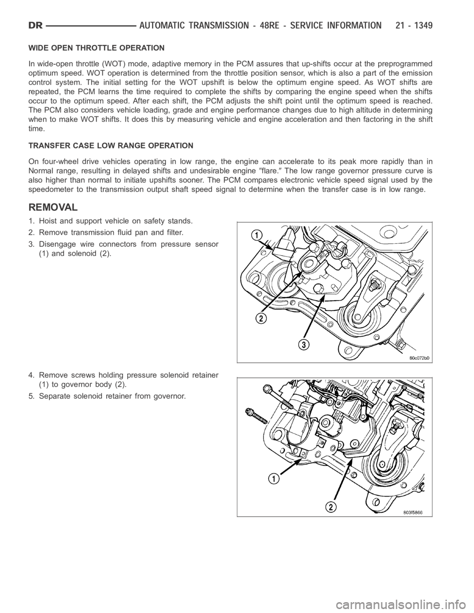
REMOVAL
1. Hoist and support vehicle on safety stands.
2. Remove transmission fluid pan and filter.
3. Disengage wire connectors from pressure sensor
(1) and solenoid (2).
4. Remove screws holding pressure solenoid retainer
(1) to governor body (2).
5. Separate solenoid retainer from governor.
Page 4086 of 5267
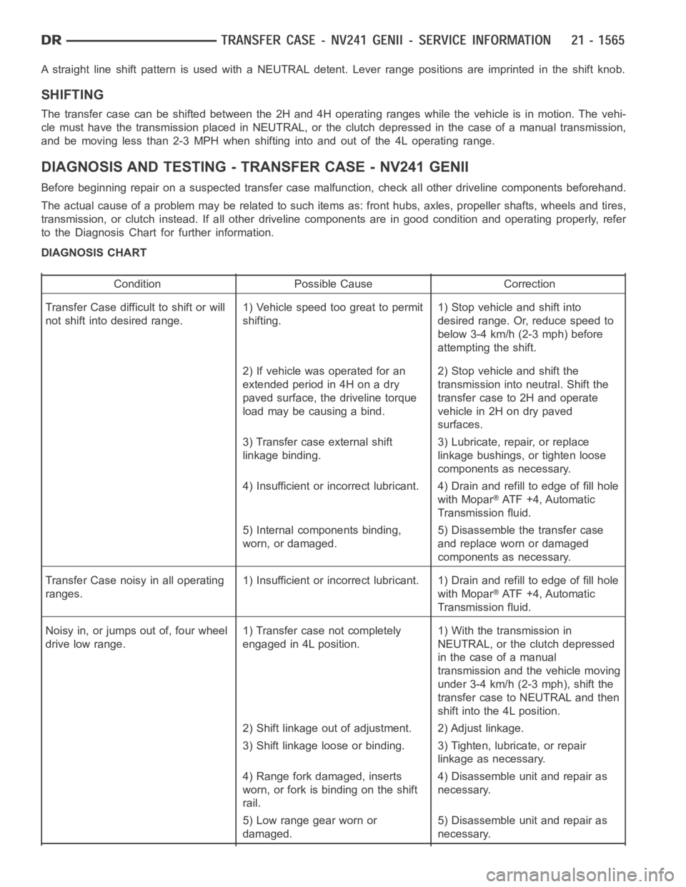
A straight line shift pattern is used with a NEUTRAL detent. Lever range positions are imprinted in the shift knob.
SHIFTING
The transfer case can be shifted between the 2H and 4H operating ranges while the vehicle is in motion. The vehi-
cle must have the transmission placed in NEUTRAL, or the clutch depressed in the case of a manual transmission,
and be moving less than 2-3 MPH when shifting into and out of the 4L operatingrange.
DIAGNOSIS AND TESTING - TRANSFER CASE - NV241 GENII
Before beginning repair on a suspected transfer case malfunction, check all other driveline components beforehand.
The actual cause of a problem may be related to such items as: front hubs, axles, propeller shafts, wheels and tires,
transmission, or clutch instead. If all other driveline components are ingood condition and operating properly, refer
to the Diagnosis Chart for further information.
DIAGNOSIS CHART
Condition Possible Cause Correction
Transfer Case difficult to shift or will
not shift into desired range.1) Vehicle speed too great to permit
shifting.1) Stop vehicle and shift into
desired range. Or, reduce speed to
below 3-4 km/h (2-3 mph) before
attempting the shift.
2) If vehicle was operated for an
extended period in 4H on a dry
paved surface, the driveline torque
load may be causing a bind.2) Stop vehicle and shift the
transmission into neutral. Shift the
transfer case to 2H and operate
vehicle in 2H on dry paved
surfaces.
3) Transfer case external shift
linkage binding.3) Lubricate, repair, or replace
linkage bushings, or tighten loose
components as necessary.
4) Insufficient or incorrect lubricant. 4) Drain and refill to edge of fillhole
with Mopar
ATF +4, Automatic
Transmission fluid.
5) Internal components binding,
worn, or damaged.5) Disassemble the transfer case
and replace worn or damaged
components as necessary.
Transfer Case noisy in all operating
ranges.1) Insufficient or incorrect lubricant. 1) Drain and refill to edge of fillhole
with Mopar
ATF +4, Automatic
Transmission fluid.
Noisy in, or jumps out of, four wheel
drive low range.1) Transfer case not completely
engaged in 4L position.1) With the transmission in
NEUTRAL, or the clutch depressed
in the case of a manual
transmission and the vehicle moving
under 3-4 km/h (2-3 mph), shift the
transfer case to NEUTRAL and then
shift into the 4L position.
2) Shift linkage out of adjustment. 2) Adjust linkage.
3) Shift linkage loose or binding. 3) Tighten, lubricate, or repair
linkage as necessary.
4) Range fork damaged, inserts
worn, or fork is binding on the shift
rail.4) Disassemble unit and repair as
necessary.
5) Low range gear worn or
damaged.5) Disassemble unit and repair as
necessary.
Page 4128 of 5267
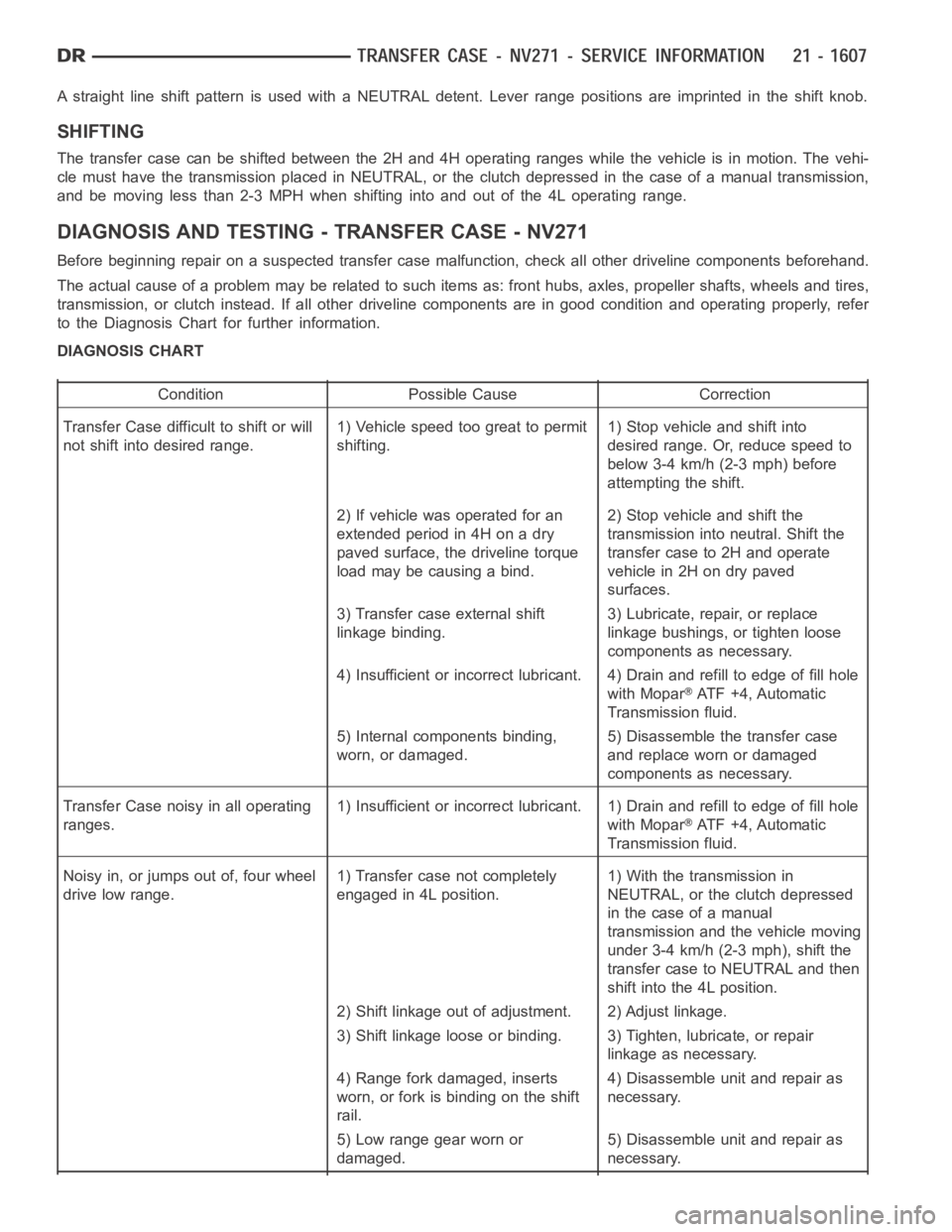
A straight line shift pattern is used with a NEUTRAL detent. Lever range positions are imprinted in the shift knob.
SHIFTING
The transfer case can be shifted between the 2H and 4H operating ranges while the vehicle is in motion. The vehi-
cle must have the transmission placed in NEUTRAL, or the clutch depressed in the case of a manual transmission,
and be moving less than 2-3 MPH when shifting into and out of the 4L operatingrange.
DIAGNOSIS AND TESTING - TRANSFER CASE - NV271
Before beginning repair on a suspected transfer case malfunction, check all other driveline components beforehand.
The actual cause of a problem may be related to such items as: front hubs, axles, propeller shafts, wheels and tires,
transmission, or clutch instead. If all other driveline components are ingood condition and operating properly, refer
to the Diagnosis Chart for further information.
DIAGNOSIS CHART
Condition Possible Cause Correction
Transfer Case difficult to shift or will
not shift into desired range.1) Vehicle speed too great to permit
shifting.1) Stop vehicle and shift into
desired range. Or, reduce speed to
below 3-4 km/h (2-3 mph) before
attempting the shift.
2) If vehicle was operated for an
extended period in 4H on a dry
paved surface, the driveline torque
load may be causing a bind.2) Stop vehicle and shift the
transmission into neutral. Shift the
transfer case to 2H and operate
vehicle in 2H on dry paved
surfaces.
3) Transfer case external shift
linkage binding.3) Lubricate, repair, or replace
linkage bushings, or tighten loose
components as necessary.
4) Insufficient or incorrect lubricant. 4) Drain and refill to edge of fillhole
with Mopar
ATF +4, Automatic
Transmission fluid.
5) Internal components binding,
worn, or damaged.5) Disassemble the transfer case
and replace worn or damaged
components as necessary.
Transfer Case noisy in all operating
ranges.1) Insufficient or incorrect lubricant. 1) Drain and refill to edge of fillhole
with Mopar
ATF +4, Automatic
Transmission fluid.
Noisy in, or jumps out of, four wheel
drive low range.1) Transfer case not completely
engaged in 4L position.1) With the transmission in
NEUTRAL, or the clutch depressed
in the case of a manual
transmission and the vehicle moving
under 3-4 km/h (2-3 mph), shift the
transfer case to NEUTRAL and then
shift into the 4L position.
2) Shift linkage out of adjustment. 2) Adjust linkage.
3) Shift linkage loose or binding. 3) Tighten, lubricate, or repair
linkage as necessary.
4) Range fork damaged, inserts
worn, or fork is binding on the shift
rail.4) Disassemble unit and repair as
necessary.
5) Low range gear worn or
damaged.5) Disassemble unit and repair as
necessary.
Page 4321 of 5267
TIRES
DESCRIPTION
TIRES
Tires are designed and engineered for each specific vehicle. They providethe best overall performance for normal
operation. The ride and handling characteristics match the vehicle’s requirements. With proper care they will give
excellent reliability, traction,skid resistance, and tread life.
Driving habits have more effect on tire life than any other factor. Carefuldrivers will obtain in most cases, much
greater mileage than severe use or careless drivers. A few of the driving habits which will shorten the life of any tire
are:
Rapid acceleration
Severe brake applications
High speed driving
Excessive speeds on turns
Striking curbs and other obstacles
Radial-ply tires are more prone to irregular tread wear. It is important tofollow the tire rotation interval (Refer to 22
- TIRES/WHEELS - STANDARD PROCEDURE). This will help to achieve a greater tread life.
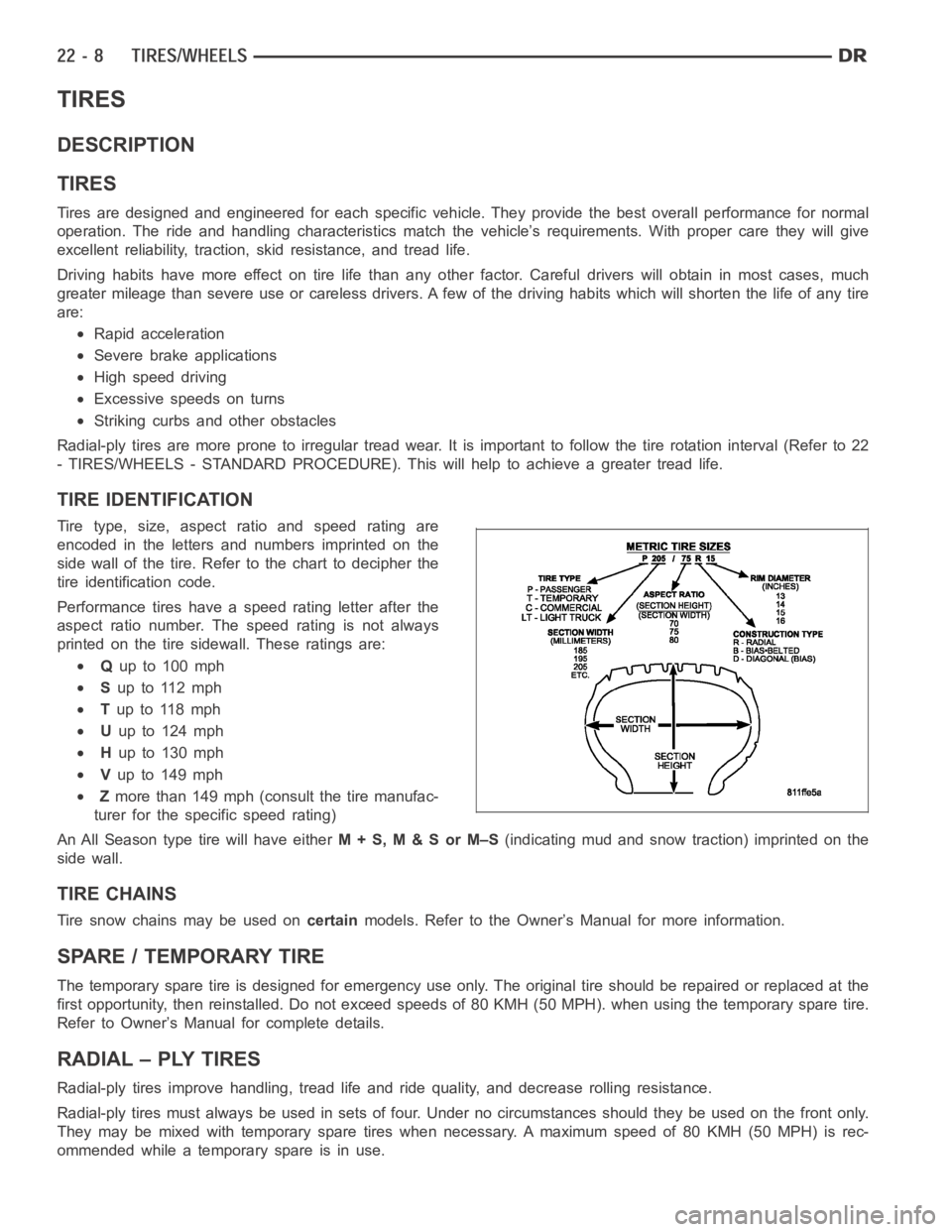
TIRE IDENTIFICATION
Tire type, size, aspect ratio and speed rating are
encoded in the letters and numbers imprinted on the
side wall of the tire. Refer to the chart to decipher the
tire identification code.
Performance tires have a speed rating letter after the
aspect ratio number. The speed rating is not always
printed on the tire sidewall. These ratings are:
Qup to 100 mph
Sup to 112 mph
Tup to 118 mph
Uup to 124 mph
Hup to 130 mph
Vup to 149 mph
Zmore than 149 mph (consult the tire manufac-
turer for the specific speed rating)
An All Season type tire will have eitherM+S,M&SorM–S(indicating mud and snow traction) imprinted on the
side wall.
TIRE CHAINS
Tire snow chains may be used oncertainmodels. Refer to the Owner’s Manual for more information.
SPARE / TEMPORARY TIRE
The temporary spare tire is designed for emergency use only. The original tire should be repaired or replaced at the
first opportunity, then reinstalled. Do not exceed speeds of 80 KMH (50 MPH). when using the temporary spare tire.
Refer to Owner’s Manual for complete details.
RADIAL – PLY TIRES
Radial-ply tires improve handling, tread life and ride quality, and decrease rolling resistance.
Radial-ply tires must always be used in sets of four. Under no circumstances should they be used on the front only.
They may be mixed with temporary spare tires when necessary. A maximum speedof80KMH(50MPH)isrec-
ommended while a temporary spare is in use.
Page 4322 of 5267
Radial-ply tires have the same load-carrying capacity as other types of tires of the same size. They also use the
same recommended inflation pressures.
The use of oversized tires, either in the front or rear of the vehicle, can cause vehicle drive train failure. This could
also cause inaccurate wheel speed signals when the vehicle is equipped with Anti-Lock Brakes.
The use of tires from different manufactures on the same vehicle is NOT recommended. The proper tire pressure
should be maintained on all four tires.
TIRE PRESSURE FOR HIGH SPEEDS
For proper tire pressure specification refer to the Owners Manual.
REPLACEMENT TIRES
The original equipment tires provide a proper balance of many characteristics such as:
Ride
Noise
Handling
Durability
Tread life
Traction
Rolling resistance
Speed capability
It is recommended that tires equivalent to the original equipment tires beused when replacement is needed.
Failure to use equivalent replacement tires may adversely affect the safety and handling of the vehicle.
The use of oversize tires may cause interference with vehicle components.Under extremes of suspension and
steering travel, interference with vehicle components may cause tire damage.
WARNING: Failure to equip the vehicle with tires having adequate speed capability can result in sudden tire
failure.
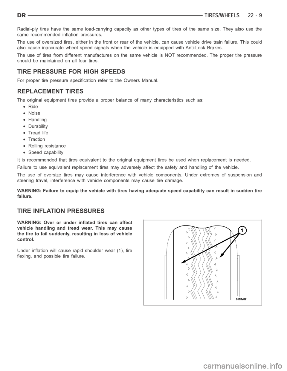
TIRE INFLATION PRESSURES
WARNING: Over or under inflated tires can affect
vehicle handling and tread wear. This may cause
the tire to fail suddenly, resulting in loss of vehicle
control.
Under inflation will cause rapid shoulder wear (1), tire
flexing, and possible tire failure.