2006 DODGE RAM SRT-10 roof rack
[x] Cancel search: roof rackPage 4341 of 5267
POSSIBLE CAUSE OF WIND NOISE
Moldings standing away from body surface can catch wind and whistle.
Gaps in sealed areas behind overhanging body flanges can cause wind-rushing sounds.
Misaligned movable components.
Missing or improperly installed plugs in pillars.
Weld burn through holes.
Improperly installed roof rack cross bars.
STANDARD PROCEDURE
BODY LUBRICATION
All mechanisms and linkages should be lubricated when necessary. This will maintain ease of operation and provide
protection against rust and excessive wear. The weatherstrip seals should be lubricated to prolong their life as well
as to improve door sealing.
All applicable exterior and interior vehicle operating mechanisms should be inspected and cleaned. Pivot/sliding con-
tact areas on the mechanisms should then be lubricated.
1. When necessary, lubricate the operating mechanisms with the specifiedlubricants.
2. Apply silicone lubricant to a clothand wipe it on door seals to avoid over-spray that can soil passenger’s cloth-
ing.
3. Before applying lubricant, the component should be wiped clean. After lubrication, any excess lubricant should be
removed.
4. The hood latch, latch release mechanism, latch striker, and safety latch should be lubricated periodically.
5. The door lock cylinders should be lubricated twice each year (preferably autumn and spring).
Spray a small amount of lock cylinder lubricant directly into the lock cylinder.
Apply a small amount to the key and insert it into the lock cylinder.
Rotate it to the locked position and then back to the unlocked position several times.
Remove the key. Wipe the lubricant from it with a clean cloth to avoid soiling of clothing.
HEAT STAKING
1. Remove trim panel.
2. Bend or move the trim panel components at the heat staked joints. Observethe heat staked locations and/or
component seams for looseness.
3. Heat stake the components.
a. If the heat staked or component seam location is loose, hold the two components tightly together and using
a soldering gun with a flat tip, melt the material securing the components together. Do not over heat the
affected area, damage to the exterior of the trim panel may occur.
b. Iftheheatstakedmaterialisbrokenormissing,useahotglueguntoapplynewmaterialtotheareatobe
repaired. The panels that are being heat staked must be held together whiletheapplyingtheglue.Oncethe
new material is in place, it may be necessary to use a soldering gun to melt the newly applied material. Do
not over heat the affected area, damage to the exterior of the trim panel mayoccur.
4. Allow the repaired area to cool and verify the repair.
5. Install trim panel.
BUZZ, SQUEAK & RATTLE
Buzz, Squeak & Rattles (BSR) may be caused by any one or more of the followingand may be corrected as indi-
cated:
Loose fasteners should be tightened to specifications.
Damaged or missing clips should be replaced.
Damaged trim panels should be replaced.
Incorrectly installed trim panels should be reinstalled properly.
Page 4603 of 5267
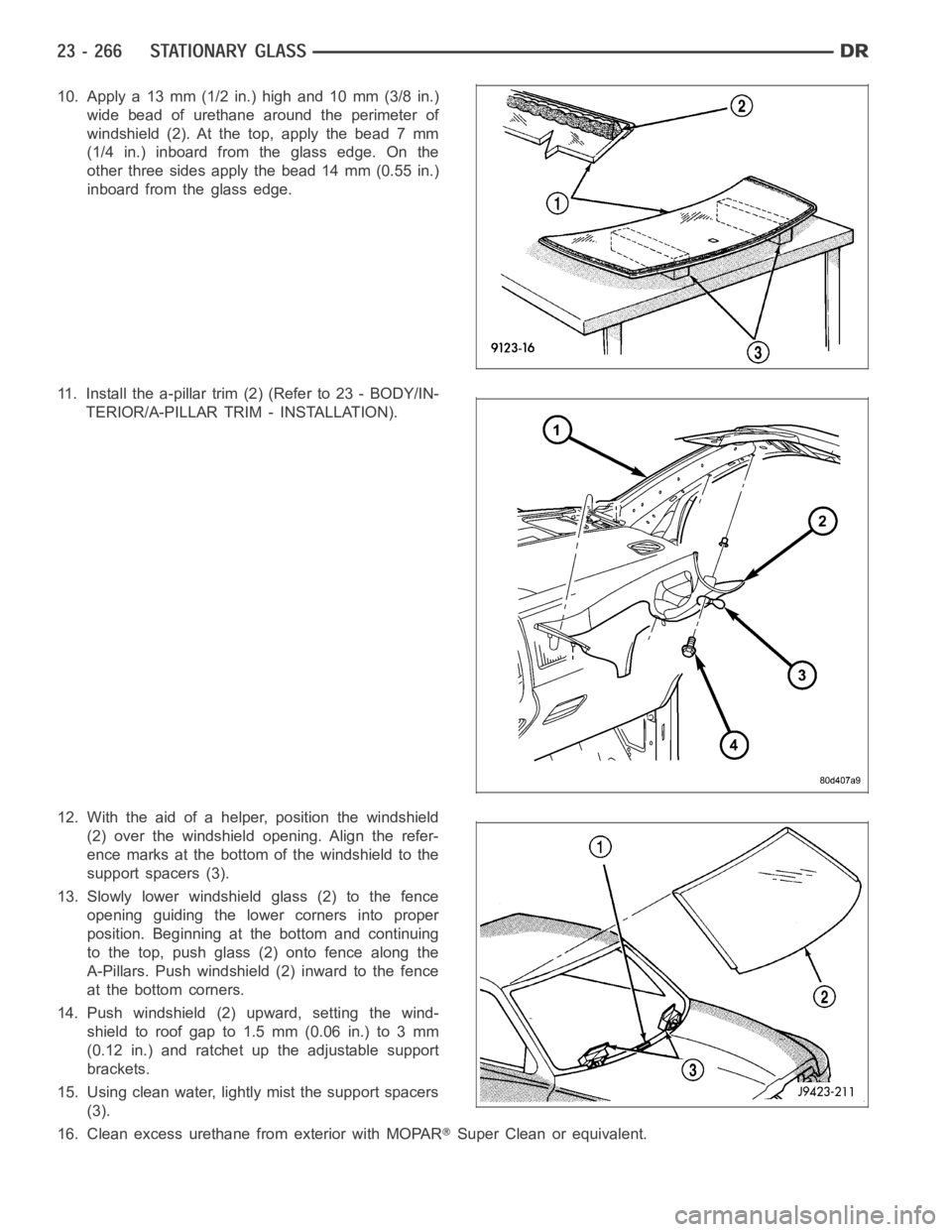
10. Apply a 13 mm (1/2 in.) high and 10 mm (3/8 in.)
wide bead of urethane around the perimeter of
windshield(2).Atthetop,applythebead7mm
(1/4 in.) inboard from the glass edge. On the
other three sides apply the bead 14 mm (0.55 in.)
inboard from the glass edge.
11. Install the a-pillar trim (2) (Refer to 23 - BODY/IN-
TERIOR/A-PILLAR TRIM - INSTALLATION).
12. With the aid of a helper, position the windshield
(2) over the windshield opening. Align the refer-
ence marks at the bottom of the windshield to the
support spacers (3).
13. Slowly lower windshield glass (2) to the fence
opening guiding the lower corners into proper
position. Beginning at the bottom and continuing
to the top, push glass (2) onto fence along the
A-Pillars. Push windshield (2) inward to the fence
at the bottom corners.
14. Push windshield (2) upward, setting the wind-
shieldtoroofgapto1.5mm(0.06in.)to3mm
(0.12 in.) and ratchet up the adjustable support
brackets.
15. Using clean water, lightly mist the support spacers
(3).
16. Clean excess urethane from exterior with MOPAR
Super Clean or equivalent.
Page 4609 of 5267
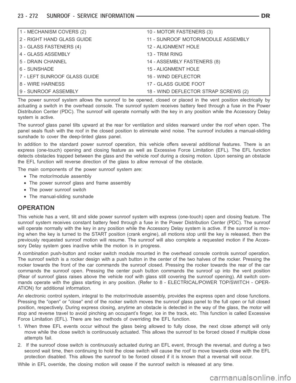
1 - MECHANISM COVERS (2) 10 - MOTOR FASTENERS (3)
2 - RIGHT HAND GLASS GUIDE 11 - SUNROOF MOTOR/MODULE ASSEMBLY
3 - GLASS FASTENERS (4) 12 - ALIGNMENT HOLE
4 - GLASS ASSEMBLY 13 - TRIM RING
5 - DRAIN CHANNEL 14 - ASSEMBLY FASTENERS (8)
6 - SUNSHADE 15 - ALIGNMENT HOLE
7 - LEFT SUNROOF GLASS GUIDE 16 - WIND DEFLECTOR
8 - WIRE HARNESS 17 - GLASS GUIDE FOOT
9 - SUNROOF ASSEMBLY 18 - WIND DEFLECTOR STRAP SCREWS (2)
The power sunroof system allows the sunroof to be opened, closed or placed in the vent position electrically by
actuating a switch in the overhead console. The sunroof system receives battery feed through a fuse in the Power
Distribution Center (PDC). The sunroof will operate normally with the keyin any position while the Accessory Delay
system is active.
The sunroof glass panel tilts upward at the rear for ventilation and slidesrearward under the roof when open. The
panel seals flush with the roof in the closed position to eliminate wind noise. The sunroof includes a manual-sliding
sunshade to cover the deep-tinted glass panel.
In addition to the standard power sunroof operation, this vehicle offers several additional features. There is an
express (one-touch) opening and closing feature as well as Excessive Force Limitation (EFL). The EFL function
detects obstacles trapped between the glass and the vehicle roof during a closing motion. Upon sensing an obstacle
the EFL function will reverse direction of the glass to allow removal of theobstacle.
The main components of thepower sunroof system are:
The motor/module assembly
The power sunroof glass and frame assembly
The power sunroof switch
The manual-sliding sunshade
OPERATION
This vehicle has a vent, tilt and slide power sunroof system with express (one-touch) open and closing feature. The
sunroof system receives constant battery feed through a fuse in the Power Distribution Center (PDC). The sunroof
will operate normally with the key in any position while the Accessory Delay system is active. If the sunroof is mov-
ing when the key is turned to the START position (crank engine), all motionsstop until the key is released, then the
previously requested sunroof motion will resume. The sunroof will also complete a requested motion if the Acces-
sory Delay system goes inactivewhile the motion is in progress.
A combination push-button and rocker switch module mounted in the overhead console controls sunroof operation.
The sunroof switch is a rocker design with a push button in the center of the two halves of the rocker. Pressing the
rocker towards the front of the car commands the sunroof closed. Pressing the rocker towards the rear of the car
commands the sunroof open. Pressing the center push button commands the sunroof up into the vent position
(Rear of sunroof glass raises above the vehicle roof with glass still covering the sunroof opening). All switch com-
mands operate with the glass startingin any position. (Refer to 8 - ELECTRICAL/POWER TOP/SWITCH - OPER-
ATION) for additional information.
An electronic control system, integralto the motor/module assembly, provides the express open and close functions.
Pressing the
openorcloseend of the rocker switch moves the sunroof glass panel to the full open or fullclosed
position, respectively. During express closing, anytime an obstacle is detected in the way of the glass, the motor will
stop and reverse travel to avoid pinching an occupant’s finger, ice in the track, etc. This function is called Excessive
Force Limitation (EFL). There are two methods of overriding the EFL function.
1. When three EFL events occur without the glass being allowed to fully close, the next close attempt will only
move while the close switch is continuously actuated. This allows the sunrooftobeforcedclosedifmultipleclose
attempts fail.
2. If the sunroof close switch is continuously actuated during an EFL event, through the reversal, and during a two
second wait time, then continuing to hold the close switch will cause the roof to move towards close with the EFL
protection disabled. This allows the sunroof to be forced closed if it is known that a reversal will occur.
While in EFL override, the closing motion will cease if the sunroof switch is released at any time.
Page 4611 of 5267
SYMPTOM POSSIBLE CAUSE
Sunroof vents and opens, but does not close. Broken or disengaged trough guide
Binding cable.
Faulty circuit.
Faulty control switch.
Faulty sunroof module.
Faulty drive motor.
Sunroof vents, but does not open. Binding cable or mechanism.
Faulty circuit.
Faulty switch.
Faulty sunroof module.
Sunroof does not vent Binding cable or mechanism.
Faulty circuit.
Faulty control switch.
Faulty sunroof module.
Sunroof water leak. Drain tubes clogged or kinked or disconnected from the
sunroof.
Glass panel improperly adjusted.
Faulty glass panel seal.
Gurgling sound from sunroof Low spot in drain hose routing, allowing waterto stand.
Wind noise from sunroof. Glass panel compression to the roof opening not consistent.
Wind deflector not deploying properly.
Glass not installed or adjusted properly.
Faulty glass panel seal.
Buzz, Squeak, Rattles from sunroof Loose or broken attaching hardware.
No lubrication in track.
Worn or broken mechanism.
Cables bunched or kinked.
Sunshade will not function or does not operate
smoothlySunshade feet are broken.
Sunshadefeetareinthewrongtrack.
Track obstructions or interference.
Trim lace incorrectly installed in track.
Glass movement not consistent or glass does
not operate smoothlyGlass and Track timing.
Glass and Track alignment.
Cables and Guide alignment.
Broken or jammed guide mechanism Mechanism cover was not installed correctly.
Page 4633 of 5267
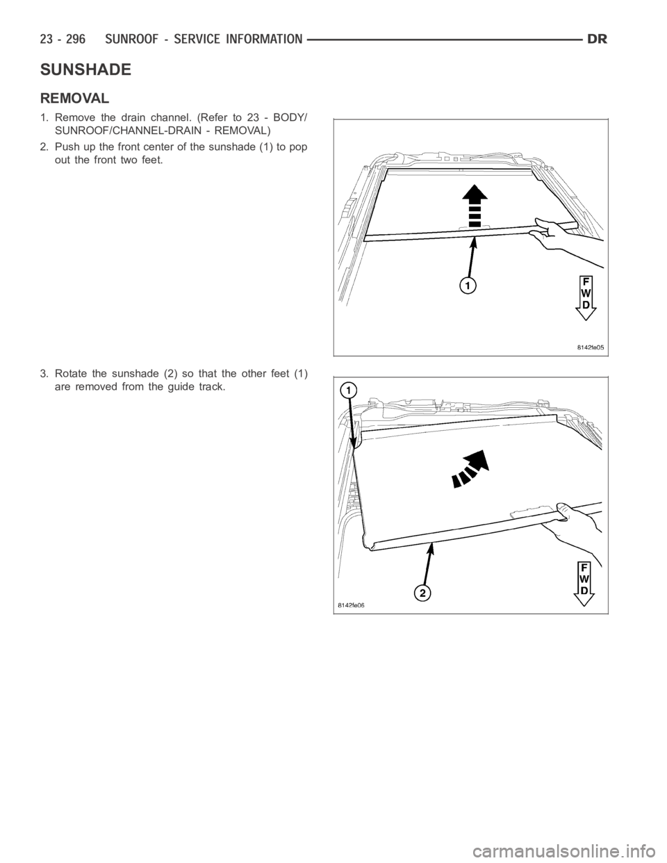
SUNSHADE
REMOVAL
1. Remove the drain channel. (Refer to 23 - BODY/
SUNROOF/CHANNEL-DRAIN - REMOVAL)
2. Push up the front center of the sunshade (1) to pop
out the front two feet.
3. Rotate the sunshade (2) so that the other feet (1)
are removed from the guide track.
Page 4634 of 5267
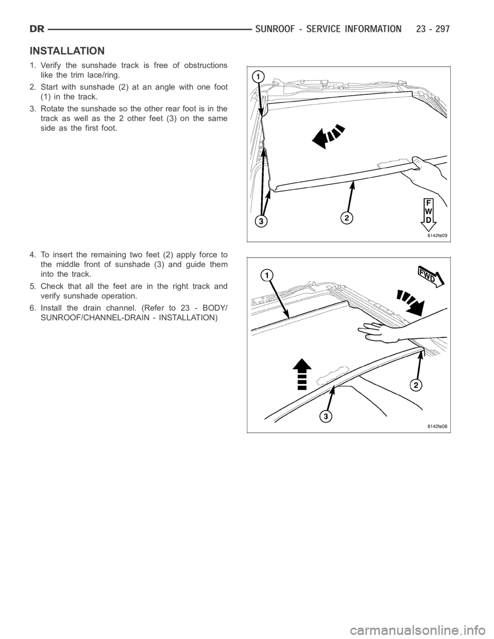
INSTALLATION
1. Verify the sunshade track is free of obstructions
like the trim lace/ring.
2. Start with sunshade (2) at an angle with one foot
(1) in the track.
3. Rotate the sunshade so the other rear foot is in the
track as well as the 2 other feet (3) on the same
side as the first foot.
4. To insert the remaining two feet (2) apply force to
the middle front of sunshade (3) and guide them
into the track.
5. Check that all the feet are in the right track and
verify sunshade operation.
6. Install the drain channel. (Refer to 23 - BODY/
SUNROOF/CHANNEL-DRAIN - INSTALLATION)
Page 4724 of 5267
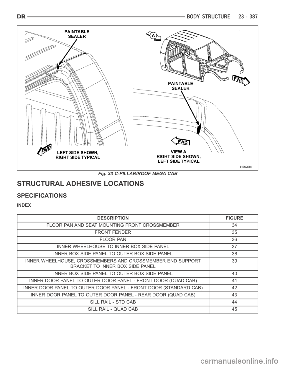
STRUCTURAL ADHESIVE LOCATIONS
SPECIFICATIONS
INDEX
DESCRIPTION FIGURE
FLOOR PAN AND SEAT MOUNTING FRONT CROSSMEMBER 34
FRONT FENDER 35
FLOOR PAN 36
INNER WHEELHOUSE TO INNER BOX SIDE PANEL 37
INNER BOX SIDE PANEL TO OUTER BOX SIDE PANEL 38
INNER WHEELHOUSE, CROSSMEMBERS AND CROSSMEMBER END SUPPORT
BRACKET TO INNER BOX SIDE PANEL39
INNER BOX SIDE PANEL TO OUTER BOX SIDE PANEL 40
INNER DOOR PANEL TO OUTER DOOR PANEL - FRONT DOOR (QUAD CAB) 41
INNER DOOR PANEL TO OUTER DOOR PANEL - FRONT DOOR (STANDARD CAB) 42
INNER DOOR PANEL TO OUTER DOOR PANEL - REAR DOOR (QUAD CAB) 43
SILL RAIL - STD CAB 44
SILL RAIL - QUAD CAB 45
Fig. 33 C-PILLAR/ROOF MEGA CAB
Page 4734 of 5267
DESCRIPTION FIGURE
OUTER BODY SIDE APERTURE TO INNER BODY SIDE APERTURE TO FLOOR SILL 98
REAR FLOOR CROSSMEMBER AND CAB BACK REINFORCEMENT TO CAB BACK
PANEL TO INNER BODY SIDE APERTURE99
CAB BACK REINFORCEMENT TO CAB BACK PANEL 100
CENTER SHOULDER BELT REINFORCEMENT AND TAPPING PLATES TO CAB BACK
REINFORCEMENT101
A-PILLAR REINFORCEMENT TO COWL SIDE PANEL TO OUTER BODY SIDE
APERTURE/APERTURE EXTENSION TO COWL SIDE PANEL102
B-PILLAR REINFORCEMENT TO OUTER ROOF PANEL TO OUTER BODY SIDE
APERTURE103
FRONT ROOF HEADER TO OUTER ROOF PANEL/ROOF BOW TO INNER BODY SIDE
APERTURE/FRONT ROOF HEADER TO A-PILLAR REINFORCEMENT104
INNER BODY SIDE APERTURE TO REAR ROOF HEADER AND OUTER BODY SIDE
APERTURE TO OUTER ROOF PANEL105
FRONT CROSSMEMBER, WHEELHOUSE CROSSMEMBER AND BRACKET SUPPORT
CROSSMEMBER TO BOX FLOOR PAN106
LONG CROSSMEMBER AND FLOOR BOX CROSS SILL TO BOX FLOOR PAN 107
TAPPING PLATES AND SUPPORT BRACKETS TO REAR CROSS BOX SILL, FRONT
WHEELHOUSE, LONG AND BRACKET SUPPORT CROSSMEMBERS108
STAKE POCKET REINFORCEMENTS AND TIE DOWN REINFORCEMENTS TO INNER
BOX SIDE PANEL109
OUTER BOX SIDE REINFORCEMENT BRACES NUT PLATES TO OUTER BOX SIDE
PANEL MOUNTING11 0
OUTER WHEELHOUSE TO OUTER BOX SIDE PANEL 111
WELD NUT STRIKER CAGE NUT, OUTER BOX SIDE PANEL AND NUT PLATE TO BOX
SIDE TAILGATE REINFORCEMENT11 2
FRONT BOX PANEL TO FRONT INNER STAKE POCKET REINFORCEMENT TO FRONT
BOX SIDE PANEL11 3
FRONT CROSSMEMBER TO FRONT BOX SIDE PANEL AND BOX FLOOR PANEL TO
BOX FRONT PANEL11 4
BOX FLOOR PANEL AND INNER WHEELHOUSE PANEL TO INNER BOX SIDE PANEL 115
FRONT CROSSMEMBER AND END SUPPORT BRACKET TO LONG CROSSMEMBER
TO INNER BOX SIDE PANEL/STAKE POCKET REINFORCEMENT AND BOX FLOOR
SILL TO OUTER TAILGATE PILLAR TO INNER TAILGATE PILLAR11 6
STAKE POCKET REINFORCEMENT AND BOX FLOOR SILL CROSSMEMBER TO
INNER TAILGATE PILLAR11 7
INNER TAILGATE PILLAR PANEL TO INNER BOX SIDE PANEL TO TIE DOWN
MOUNTING REINFORCEMENT11 8
BOX FLOOR SILL CROSSMEMBER TO INNER BOX SIDE PANEL 119
INNER TAILGATE PILLAR TO TAILGATE BOX SIDE REINFORCEMENT TO OUTER
TAILGATE PILLAR120
BOX SIDE PANEL AND OUTER TAILGATE PILLAR TO OUTER BOX SIDE PANEL 121
FRONT BOX PANEL TO OUTER BOX SIDE PANEL 122
INNER BOX SIDE PANEL AND INNER TAILGATE PILLAR TO OUTER BOX SIDE PANEL 123
OUTER WHEELHOUSE PANEL TO INNER WHEELHOUSE PANEL 124
FRONT CROSSMEMBER, LONG CROSSMEMBER, AND WHEELHOUSE
CROSSMEMBER TO FLOOR PAN125
WHEELHOUSE CROSSMEMBER, LONG CROSSMEMBER AND REAR CROSS BOX
SILL TO BOX FLOOR PAN126