2006 DODGE RAM SRT-10 maintenance schedule
[x] Cancel search: maintenance schedulePage 1598 of 5267
OIL
STANDARD PROCEDURE - ENGINE OIL SERVICE
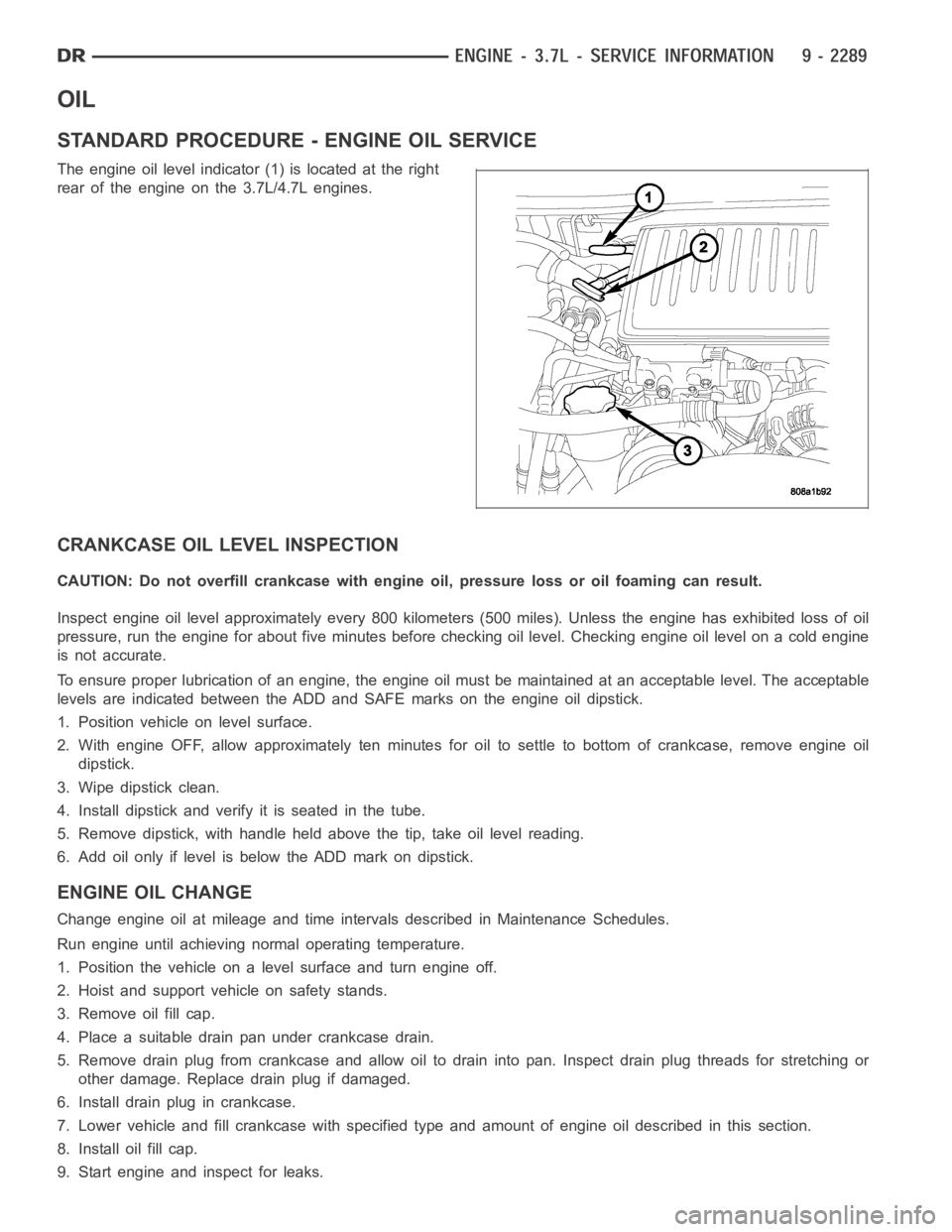
The engine oil level indicator (1) is located at the right
rear of the engine on the 3.7L/4.7L engines.
CRANKCASE OIL LEVEL INSPECTION
CAUTION: Do not overfill crankcase with engine oil, pressure loss or oil foaming can result.
Inspect engine oil level approximately every 800 kilometers (500 miles).Unless the engine has exhibited loss of oil
pressure, run the engine for about five minutes before checking oil level.Checking engine oil level on a cold engine
is not accurate.
To ensure proper lubrication of an engine, the engine oil must be maintained at an acceptable level. The acceptable
levels are indicated between the ADD and SAFE marks on the engine oil dipstick.
1. Position vehicle on level surface.
2. With engine OFF, allow approximately ten minutes for oil to settle to bottom of crankcase, remove engine oil
dipstick.
3. Wipe dipstick clean.
4. Install dipstick and verify it is seated in the tube.
5. Remove dipstick, with handle held above the tip, take oil level reading.
6. Add oil only if level is below the ADD mark on dipstick.
ENGINE OIL CHANGE
Change engine oil at mileage and time intervals described in Maintenance Schedules.
Run engine until achieving normal operating temperature.
1. Position the vehicle on a level surface and turn engine off.
2. Hoist and support vehicle on safety stands.
3. Remove oil fill cap.
4. Place a suitable drain pan under crankcase drain.
5. Remove drain plug from crankcase and allow oil to drain into pan. Inspectdrain plug threads for stretching or
other damage. Replace drain plug if damaged.
6. Install drain plug in crankcase.
7. Lower vehicle and fill crankcase with specified type and amount of engine oil described in this section.
8. Install oil fill cap.
9. Start engine and inspect for leaks.
Page 1723 of 5267
OIL
STANDARD PROCEDURE - ENGINE OIL SERVICE
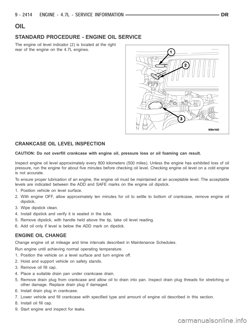
The engine oil level indicator (2) is located at the right
rear of the engine on the 4.7L engines.
CRANKCASE OIL LEVEL INSPECTION
CAUTION: Do not overfill crankcase with engine oil, pressure loss or oil foaming can result.
Inspect engine oil level approximately every 800 kilometers (500 miles).Unless the engine has exhibited loss of oil
pressure, run the engine for about five minutes before checking oil level.Checking engine oil level on a cold engine
is not accurate.
To ensure proper lubrication of an engine, the engine oil must be maintained at an acceptable level. The acceptable
levels are indicated between the ADD and SAFE marks on the engine oil dipstick.
1. Position vehicle on level surface.
2. With engine OFF, allow approximately ten minutes for oil to settle to bottom of crankcase, remove engine oil
dipstick.
3. Wipe dipstick clean.
4. Install dipstick and verify it is seated in the tube.
5. Remove dipstick, with handle held above the tip, take oil level reading.
6. Add oil only if level is below the ADD mark on dipstick.
ENGINE OIL CHANGE
Change engine oil at mileage and time intervals described in Maintenance Schedules.
Run engine until achieving normal operating temperature.
1. Position the vehicle on a level surface and turn engine off.
2. Hoist and support vehicle on safety stands.
3. Remove oil fill cap.
4. Place a suitable drain pan under crankcase drain.
5. Remove drain plug from crankcase and allow oil to drain into pan. Inspectdrain plug threads for stretching or
other damage. Replace drain plug if damaged.
6. Install drain plug in crankcase.
7. Lower vehicle and fill crankcase with specified type and amount of engine oil described in this section.
8. Install oil fill cap.
9. Start engine and inspect for leaks.
Page 1877 of 5267
OIL
STANDARD PROCEDURE - ENGINE OIL SERVICE
The engine oil level indicator is located at the left hand of the engine on the 5.7L engines.
CRANKCASE OIL LEVEL INSPECTION
CAUTION: Do not overfill crankcase with engine oil, pressure loss or oil foaming can result.
Inspect engine oil level approximately every 800 kilometers (500 miles).Unless the engine has exhibited loss of oil
pressure, run the engine for about ten minutes before checking oil level. Checking engine oil level on a cold engine
is not accurate.
To ensure proper lubrication of an engine, the engine oil must be maintained at an acceptable level. The acceptable
levels are indicated between the ADD and SAFE marks on the engine oil dipstick.
1. Position vehicle on level surface.
2. With engine OFF, allow approximately five minutes for oil to settle to bottom of crankcase, remove engine oil
dipstick.
3. Wipe dipstick clean.
4. Install dipstick and verify it is seated in the tube.
5. Remove dipstick, with handle held above the tip, take oil level reading.
6. Add oil only if level is below the ADD mark on dipstick.
ENGINE OIL CHANGE
Change engine oil at mileage and time intervals described in Maintenance Schedules (Refer to LUBRICATION &
MAINTENANCE/MAINTENANCESCHEDULES - DESCRIPTION).
Run engine until achieving normal operating temperature.
1. Position the vehicle on a level surface and turn engine off.
2. Hoist and support vehicle on safety stands.
3. Remove oil fill cap.
4. Place a suitable drain pan under crankcase drain.
5. Remove drain plug from crankcase and allow oil to drain into pan. Inspectdrain plug threads for stretching or
other damage. Replace drain plug if damaged.
6. Install drain plug in crankcase. Torque to 34 Nꞏm ( 25 ft. lbs.).
7. Lower vehicle and fill crankcase with specified type and amount of engine oil described in this section.
8. Install oil fill cap.
9. Start engine and inspect for leaks.
10. Stop engine and inspect oil level.
USED ENGINE OIL DISPOSAL
Care should be exercised when disposing used engine oil after it has been drained from a vehicle engine. Refer to
the WARNING at beginning of this section.
Page 1997 of 5267
LUBRICATION
DESCRIPTION
A gear driven gerotor type oil pump is mounted behind the front gear cover inthe lower right portion on the engine.
OPERATION
A gerotor style oil pump draws oil from the crankcase through the suction tube and delivers it through the block
where it enters the oil cooler cover and pressure regulator valve. When oilpressure exceeds 517 kPa (75 PSI), the
valve opens exposing the dump port, which routes excess oil back to the oil pump.
At the same time, oil is directed to a cast in passage in the oil cooler cover,leading to the oil cooler element. As the
oil travels through the element plates, it is cooled by engine coolant traveling past the outside of the plates. It is
then routed to the oil filter head and through a full flow oil filter. If a plugged filter is encountered, the filter by-pass
valve opens, allowing unfiltered oil to lubricate the engine. This condition can be avoided by frequent oil and filter
changes, per the maintenance schedules found in the owners manual. The by-pass valve is calibrated to open when
it sees a pressure drop of more than 345 kPa (50 psi) across the oil filter.
The oil filter head then divides the oil between the engine and the turbocharger. The turbocharger receives filtered,
cooled and pressurized oil through a supply line from the filter head. The oil lubricates the turbocharger and returns
to the pan by way of a drain tube connecting the bottom of the turbocharger toa tube in the cylinder block.
Page 2088 of 5267
OIL
STANDARD PROCEDURE
CHECKING ENGINE OIL LEVEL
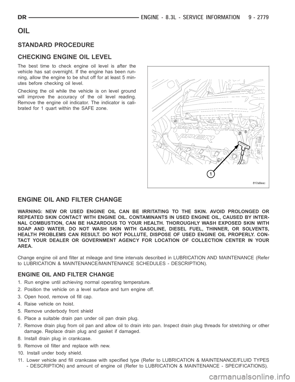
The best time to check engine oil level is after the
vehicle has sat overnight. If the engine has been run-
ning, allow the engine to be shut off for at least 5 min-
utes before checking oil level.
Checking the oil while the vehicle is on level ground
will improve the accuracy of the oil level reading.
Remove the engine oil indicator. The indicator is cali-
brated for 1 quart within the SAFE zone.
ENGINE OIL AND FILTER CHANGE
WARNING: NEW OR USED ENGINE OIL CAN BE IRRITATING TO THE SKIN. AVOID PROLONGED OR
REPEATED SKIN CONTACT WITH ENGINE OIL. CONTAMINANTS IN USED ENGINE OIL, CAUSED BY INTER-
NAL COMBUSTION, CAN BE HAZARDOUS TO YOUR HEALTH. THOROUGHLY WASH EXPOSED SKIN WITH
SOAP AND WATER. DO NOT WASH SKIN WITH GASOLINE, DIESEL FUEL, THINNER, OR SOLVENTS,
HEALTH PROBLEMS CAN RESULT. DO NOT POLLUTE, DISPOSE OF USED ENGINE OIL PROPERLY. CON-
TACT YOUR DEALER OR GOVERNMENT AGENCY FOR LOCATION OF COLLECTION CENTER INYOUR
AREA.
Change engine oil and filter at mileage and time intervals described in LUBRICATION AND MAINTENANCE (Refer
to LUBRICATION & MAINTENANCE/MAINTENANCE SCHEDULES - DESCRIPTION).
ENGINE OIL AND FILTER CHANGE
1. Run engine until achieving normal operating temperature.
2. Position the vehicle on a level surface and turn engine off.
3. Open hood, remove oil fill cap.
4. Raise vehicle on hoist.
5. Remove underbody front shield
6. Place a suitable drain pan under oil pan drain plug.
7. Remove drain plug from oil pan and allow oil to drain into pan. Inspect drain plug threads for stretching or other
damage. Replace drain plug and gasket if damaged.
8. Install drain plug in crankcase.
9. Remove oil filter and replace with new.
10. Install under body shield.
11. Lower vehicle and fill crankcase with specified type (Refer to LUBRICATION & MAINTENANCE/FLUID TYPES
- DESCRIPTION) and amount of engine oil (Refer to LUBRICATION & MAINTENANCE - SPECIFICATIONS).
Page 2241 of 5267
OPERATION
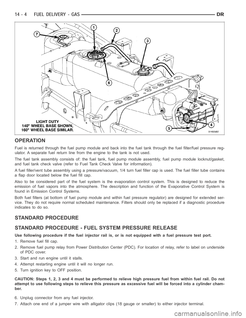
Fuel is returned through the fuel pump module and back into the fuel tank through the fuel filter/fuel pressure reg-
ulator. A separate fuel return line from the engine to the tank is not used.
The fuel tank assembly consists of: the fuel tank, fuel pump module assembly, fuel pump module locknut/gasket,
and fuel tank check valve (refer to Fuel Tank Check Valve for information).
A fuel filler/vent tube assembly using apressure/vacuum,1/4 turn fuel filler cap is used. The fuel filler tube contains
a flap door located below the fuel fill cap.
Also to be considered part of the fuelsystem is the evaporation control system. This is designed to reduce the
emission of fuel vapors into the atmosphere. The description and functionof the Evaporative Control System is
found in Emission Control Systems.
Both fuel filters (at bottom of fuel pump module and within fuel pressure regulator) are designed for extended ser-
vice. They do not require normal scheduled maintenance. Filters should only be replaced if a diagnostic procedure
indicates to do so.
STANDARD PROCEDURE
STANDARD PROCEDURE - FUEL SYSTEM PRESSURE RELEASE
Use following procedure if the fuel injector rail is, or is not equipped with a fuel pressure test port.
1. Remove fuel fill cap.
2. Remove fuel pump relay from Power Distribution Center (PDC). For location of relay, refer to label on underside
of PDC cover.
3. Start and run engine until it stalls.
4. Attempt restarting engine until it will no longer run.
5. Turn ignition key to OFF position.
CAUTION: Steps 1, 2, 3 and 4 must be performed to relieve high pressure fuel from within fuel rail. Do not
attempt to use following steps to relieve this pressure as excessive fuel will be forced into a cylinder cham-
ber.
6. Unplug connector from any fuel injector.
7. Attach one end of a jumper wire with alligator clips (18 gauge or smaller)to either injector terminal.
Page 2246 of 5267
FUEL FILTER/PRESSURE REGULATOR
DESCRIPTION
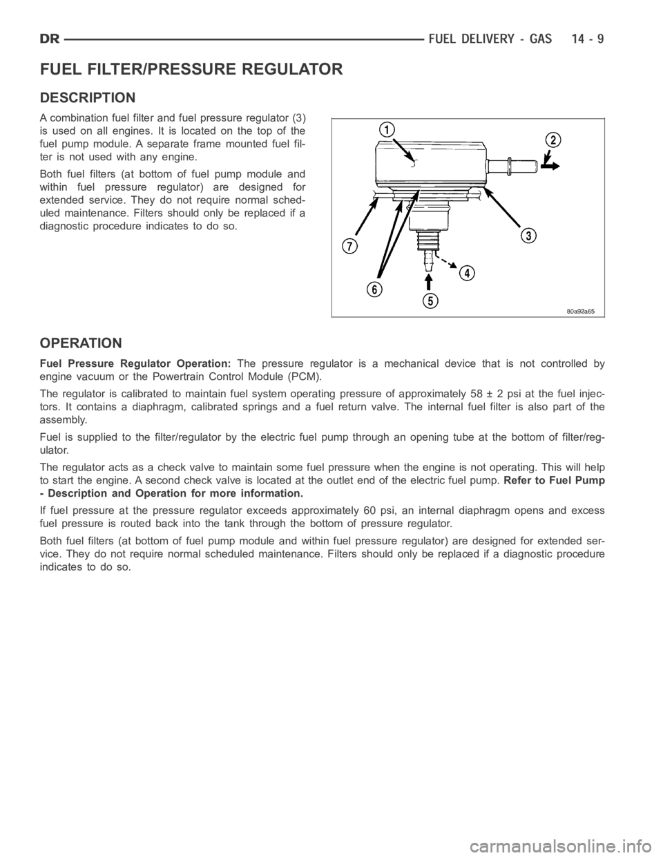
A combination fuel filter and fuel pressure regulator (3)
is used on all engines. It is located on the top of the
fuel pump module. A separate frame mounted fuel fil-
ter is not used with any engine.
Both fuel filters (at bottom of fuel pump module and
within fuel pressure regulator) are designed for
extended service. They do not require normal sched-
uled maintenance. Filters should only be replaced if a
diagnostic procedure indicates to do so.
OPERATION
Fuel Pressure Regulator Operation:The pressure regulator is a mechanical device that is not controlled by
engine vacuum or the Powertrain Control Module (PCM).
The regulator is calibrated to maintain fuel system operating pressure ofapproximately 58 ± 2 psi at the fuel injec-
tors. It contains a diaphragm, calibrated springs and a fuel return valve.The internal fuel filter is also part of the
assembly.
Fuel is supplied to the filter/regulator by the electric fuel pump throughan opening tube at the bottom of filter/reg-
ulator.
The regulator acts as a check valve to maintain some fuel pressure when the engine is not operating. This will help
to start the engine. A second check valve is located at the outlet end of the electric fuel pump.Refer to Fuel Pump
- Description and Operation for more information.
If fuel pressure at the pressure regulator exceeds approximately 60 psi, an internal diaphragm opens and excess
fuel pressure is routed back into the tank through the bottom of pressure regulator.
Both fuel filters (at bottom of fuel pump module and within fuel pressure regulator) are designed for extended ser-
vice. They do not require normal scheduled maintenance. Filters should only be replaced if a diagnostic procedure
indicates to do so.
Page 2348 of 5267
FILTER - FUEL / WATER SEPARATOR
DESCRIPTION
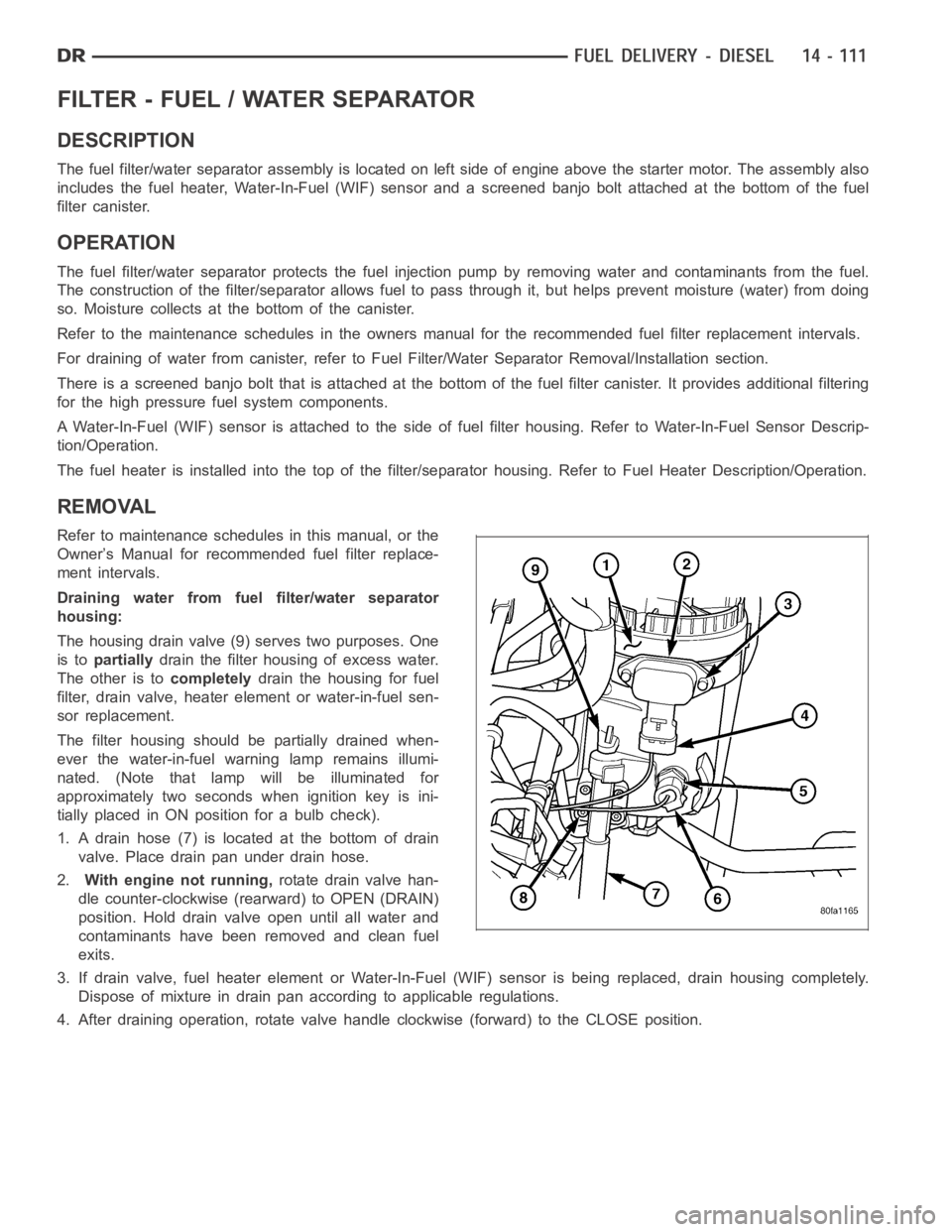
The fuel filter/water separator assembly is located on left side of engineabove the starter motor. The assembly also
includes the fuel heater, Water-In-Fuel (WIF) sensor and a screened banjobolt attached at the bottom of the fuel
filter canister.
OPERATION
The fuel filter/water separator protects the fuel injection pump by removing water and contaminants from the fuel.
The construction of the filter/separator allows fuel to pass through it, but helps prevent moisture (water) from doing
so. Moisture collects at the bottom of the canister.
Refer to the maintenance schedules in the owners manual for the recommended fuel filter replacement intervals.
For draining of water from canister, refer to Fuel Filter/Water SeparatorRemoval/Installation section.
There is a screened banjo bolt that is attached at the bottom of the fuel filter canister. It provides additional filtering
for the high pressure fuel system components.
A Water-In-Fuel (WIF) sensor is attached to the side of fuel filter housing. Refer to Water-In-Fuel Sensor Descrip-
tion/Operation.
The fuel heater is installed into the top of the filter/separator housing.Refer to Fuel Heater Description/Operation.
REMOVAL
Refer to maintenance schedules in this manual, or the
Owner’s Manual for recommended fuel filter replace-
ment intervals.
Draining water from fuel filter/water separator
housing:
The housing drain valve (9) serves two purposes. One
is topartiallydrain the filter housing of excess water.
The other is tocompletelydrain the housing for fuel
filter, drain valve, heater element or water-in-fuel sen-
sor replacement.
The filter housing should be partially drained when-
ever the water-in-fuel warning lamp remains illumi-
nated. (Note that lamp will be illuminated for
approximately two seconds when ignition key is ini-
tially placed in ON position for a bulb check).
1. A drain hose (7) is located at the bottom of drain
valve. Place drain pan under drain hose.
2.With engine not running,rotate drain valve han-
dle counter-clockwise (rearward) to OPEN (DRAIN)
position. Hold drain valve open until all water and
contaminants have been removed and clean fuel
exits.
3. If drain valve, fuel heater element or Water-In-Fuel (WIF) sensor is being replaced, drain housing completely.
Dispose of mixture in drain pan according to applicable regulations.
4. After draining operation, rotate valve handle clockwise (forward) to the CLOSE position.