2006 DODGE RAM SRT-10 parking brake
[x] Cancel search: parking brakePage 439 of 5267

3.EXCESSIVE RESISTANCE IN THE BATTERY CIRCUIT
Turn the ignition off.
Check the Battery Cables for excessive resistance using the service information procedure.
Did either Battery Cable have a voltage drop greater than 0.2 of a volt?
Ye s>>
Repair the excessive resistance in the Battery circuit.
Perform the POWERTRAIN VERIFICATION TEST. (Refer to 9 - ENGINE - STANDARD PROCEDURE)
No>>
Go To 4
4.STARTER RELAY
Turn ignition off.
Remove the Starter Relay from IPM.
CAUTION: The Parking Brake must be on and the Transmission must be in park for a vehicle equipped with
an automatic transmission.
WARNING: When the engine is operating, do not stand in direct line with the fan. Do not put your hands
near the pulleys, belts, or fan. Do notwear loose clothing. Failure to follow these instructions can result in
personal injury or death.
Briefly connect a jumper wire from the Internal Fused B+ circuit to the (T750) Starter Relay Output circuit.
Did the Starter Motor crank the engine?
Ye s>>
Go To 5
No>>
Go To 7
5.(T751) FUSED IGNITION SWITCH OUTPUT CIRCUIT
Ignition on, engine not running.
Using a 12-volt test light, probe the (T751) Fused Ignition Switch Output circuit in the Starter Relay connector.
While observing 12-volt test light, hold ignition key in the start position.
Does the test light illuminate brightly?
Ye s>>
Go To 6
No>>
Repair the excessive resistance in the(T751)FusedIgnitionSwitchOutput circuit. Inspect related fuses
and repair as necessary.
Perform the POWERTRAIN VERIFICATION TEST. (Refer to 9 - ENGINE - STANDARD PROCEDURE)
Page 2852 of 5267
When Monitored:
Continuously with the ignition on, engine running, with the transmissionin gear.
Set Condition:
The PCM continuously monitors Actual Line Pressure and compares it to DesiredLinePressure.IftheActual
Line Pressure reading is more than 172.4 kPa (25 psi) higher than the Desired Line Pressure, but is less than
the highest Line Pressure ever used in the current gear, the DTC sets.
Possible Causes
RELATED DTC’S PRESENT
LINE PRESSURE CONNECTOR AND WIRING
INTERNAL TRANSMISSION
POWERTRAIN CONTROL MODULE
Always perform the 42RLE Pre-Diagnostic Troubleshooting procedure before proceeding. (Refer to 21 -
TRANSMISSION/TRANSAXLE/AUTOMATIC - 42RLE - STANDARD PROCEDURE)
Theory of Operation
Line pressure is electronically controlled by the Transmission Control System and is measured by the Line Pressure
Sensor (LPS). The desired line pressure is continuously being compared tothe actual line pressure and is regulated
by electronically changing the dutycycle of the Pressure Control Solenoid (PCS). (5% duty cycle = solenoid off =
max line pressure, 62% duty cycle =solenoid on = min line pressure).
The Transmission Control System calculates the desired line pressure based on inputs from the transmission and
engine. A calculated torque input to the transmission is used as the primary input of the desired line pressure cal-
culation and is called Torque Based Line Pressure. In addition, the line pressure is set to a preset level 827 to 931
kPa (120 to 135 psi) during shifts and in Park and Neutral to ensure consistent shift quality.
Diagnostic Test
1.DETERMINING IF RELATED DTCS ARE PRESENT
With the scan tool, check for other transmission DTCs.
Are there any other line pressure related DTCs present?
Ye s>>
Refer to the Transmission category and perform the appropriate symptom. Perform the test for P0934
and/or P0935 first if present.
No>>
Go To 2
2.COMPARE ACTUAL LINE PRESSURE TO DESIRED LINE PRESSURE
CAUTION: Apply Parking Brake
Start the engine.
CAUTION: Firmly apply the brakes.
With the scan tool, monitor the Line Pressure, Desired Line Pressure and the TPS degrees.
While firmly applying the brakes, place the shifter in reverse, then slowly press the accelerator pedal to a TPS
degree of 15°.
Compare the Line Pressure reading to the Desired Line Pressure reading on the scan tool.
Does the Line Pressure stay within ± 34 kPa or 5 psi of the Desired Line Pressure?
No>>
Go To 3
Ye s>>
Go To 5
Page 3015 of 5267
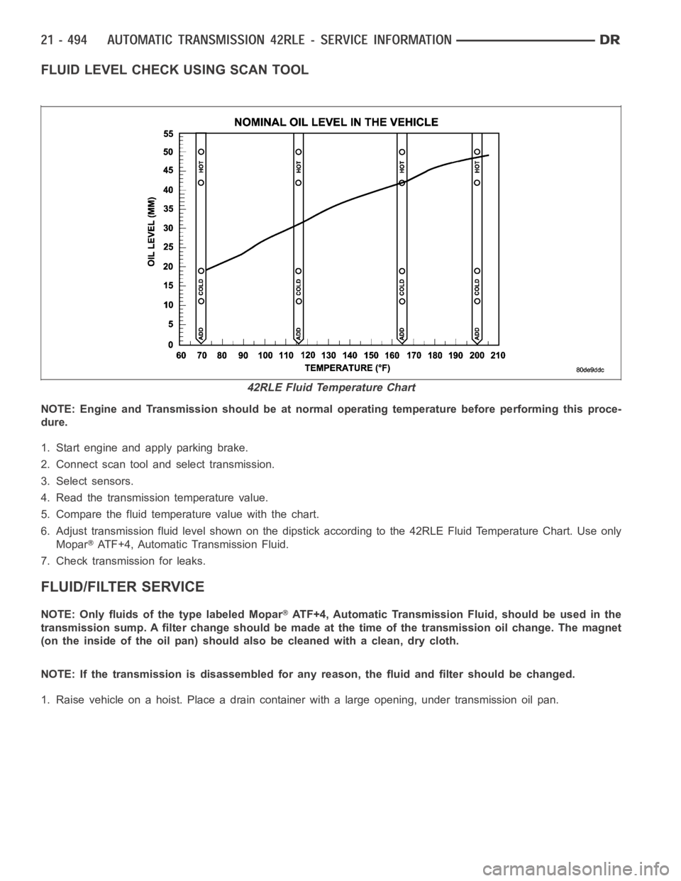
FLUID LEVEL CHECK USING SCAN TOOL
NOTE: Engine and Transmission should be at normal operating temperature before performing this proce-
dure.
1. Start engine and apply parking brake.
2. Connect scan tool and select transmission.
3. Select sensors.
4. Read the transmission temperature value.
5. Compare the fluid temperature value with the chart.
6. Adjust transmission fluid level shown on the dipstick according to the 42RLE Fluid Temperature Chart. Use only
Mopar
ATF+4, Automatic Transmission Fluid.
7. Check transmission for leaks.
FLUID/FILTER SERVICE
NOTE: Only fluids of the type labeled MoparATF+4, Automatic Transmission Fluid, should be used in the
transmission sump. A filter change should be made at the time of the transmission oil change. The magnet
(on the inside of the oil pan) should also be cleaned with a clean, dry cloth.
NOTE: If the transmission is disassembled for any reason, the fluid and filter should be changed.
1. Raise vehicle on a hoist. Place a drain container with a large opening, under transmission oil pan.
42RLE Fluid Temperature Chart
Page 3016 of 5267
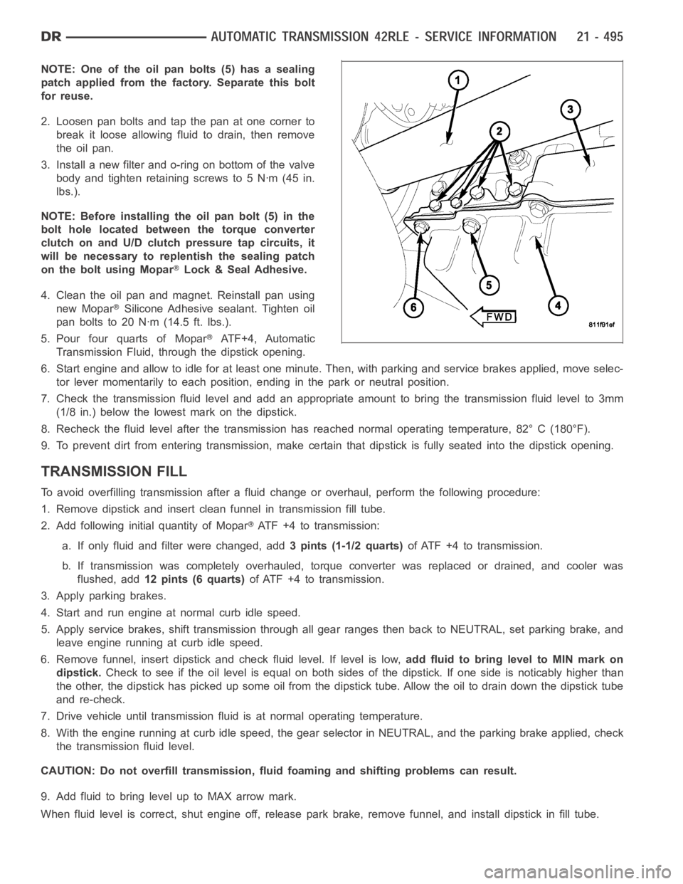
NOTE: One of the oil pan bolts (5) has a sealing
patch applied from the factory. Separate this bolt
for reuse.
2. Loosen pan bolts and tap the pan at one corner to
break it loose allowing fluid to drain, then remove
the oil pan.
3. Install a new filter and o-ring on bottom of the valve
body and tighten retaining screws to 5 Nꞏm (45 in.
lbs.).
NOTE: Before installing the oil pan bolt (5) in the
bolt hole located between the torque converter
clutch on and U/D clutch pressure tap circuits, it
will be necessary to replentish the sealing patch
on the bolt using Mopar
Lock & Seal Adhesive.
4. Clean the oil pan and magnet. Reinstall pan using
new Mopar
Silicone Adhesive sealant. Tighten oil
pan bolts to 20 Nꞏm (14.5 ft. lbs.).
5. Pour four quarts of Mopar
AT F + 4 , A u t o m a t i c
Transmission Fluid, through the dipstick opening.
6. Start engine and allow to idle for at least one minute. Then, with parkingand service brakes applied, move selec-
tor lever momentarily to each position, ending in the park or neutral position.
7. Check the transmission fluid level and add an appropriate amount to bring the transmission fluid level to 3mm
(1/8 in.) below the lowest mark on the dipstick.
8. Recheck the fluid level after the transmission has reached normal operating temperature, 82° C (180°F).
9. To prevent dirt from entering transmission, make certain that dipstickis fully seated into the dipstick opening.
TRANSMISSION FILL
To avoid overfilling transmission after a fluid change or overhaul, perform the following procedure:
1. Remove dipstick and insert clean funnel in transmission fill tube.
2. Add following initial quantity of Mopar
ATF+4totransmission:
a. If only fluid and filter were changed, add3 pints (1-1/2 quarts)of ATF +4 to transmission.
b. If transmission was completely overhauled, torque converter was replaced or drained, and cooler was
flushed, add12 pints (6 quarts)of ATF +4 to transmission.
3. Apply parking brakes.
4. Start and run engine at normal curb idle speed.
5. Apply service brakes, shift transmission through all gear ranges then back to NEUTRAL, set parking brake, and
leave engine running at curb idle speed.
6. Remove funnel, insert dipstick andcheck fluid level. If level is low,add fluid to bring level to MIN mark on
dipstick.Check to see if the oil level is equal on both sides of the dipstick. If one side is noticably higher than
the other, the dipstick has picked up some oil from the dipstick tube. Allowthe oil to drain down the dipstick tube
and re-check.
7. Drive vehicle until transmission fluid is at normal operating temperature.
8. With the engine running at curb idle speed, the gear selector in NEUTRAL,and the parking brake applied, check
the transmission fluid level.
CAUTION: Do not overfill transmission, fluid foaming and shifting problems can result.
9. Add fluid to bring level up to MAX arrow mark.
When fluid level is correct, shut engine off, release park brake, remove funnel, and install dipstick in fill tube.
Page 3142 of 5267
When Monitored:
The transmission gear ratio is monitored continuously while the transmission is in gear.
Set Condition:
If there is an excessive change in output RPM in any gear. This DTC can take upto five minutes of problem
identification beforeilluminating the MIL.
Possible Causes
(T14) OUTPUT SPEED SENSOR SIGNAL CIRCUIT OPEN
(T13) SPEED SENSOR GROUND CIRCUIT OPEN
(T14) OUTPUT SPEED SENSOR SIGNAL CIRCUIT SHORT TO GROUND
(T13) SPEED SENSOR GROUND CIRCUIT SHORT TO GROUND
(T14) OUTPUT SPEED SENSOR SIGNAL CIRCUIT SHORT TO VOLTAGE
(T13) SPEED SENSOR GROUND CIRCUIT SHORT TO VOLTAGE
OUTPUT SPEED SENSOR
POWERTRAIN CONTROL MODULE
Always perform the 45RFE/545RFE Pre-Diagnostic Troubleshooting Procedure before proceeding. (Refer to
21 - TRANSMISSION/TRANSAXLE/AUTOMATIC - 45RFE/545RFE - STANDARD PROCEDURE)
Theory of Operation
The transmission system uses two speed sensors, one to measure input RPM and one to measure output RPM.
These inputs are essential for proper transmission operation. Therefore, the integrity of this data is verified through
the following checks:
1) When in gear, if the gear ratio does not compare to a known gear ratio, the corresponding in-gear trouble code
is set (codes P0731 through P0736).
2) An excessive change in input or output speeds indicating signal intermittent will result in codes P0715 and/or
P0720 being set.
3) If the common speed sensor ground circuit is lost, both sensor inputs will read the signal from the input speed
sensor at idle in neutral. Since the input speed sensor has 60 teeth and the output speed sensor has 30 teeth, this
results in a an apparent speed ratio of 1:2 and may cause the DTC P1794 to set.
Diagnostic Test
1.CHECK TO SEE IF DTC P0720 IS CURRENT
Turn the ignition off to the lock position.
CAUTION: Properly support the vehicle and raise all drive wheels off the ground.
Release the parking brake.
Start the engine in park.
Place the transmission gear selector in drive, release foot from brake.
WARNING: Be sure to keep hands and feet clear of rotation wheels.
With the scan tool, monitor the Output Speed Sensor RPM.
Is the Output Speed Sensor RPM below 100 RPM?
Ye s>>
Go To 2
No>>
Go To 9
Page 3207 of 5267
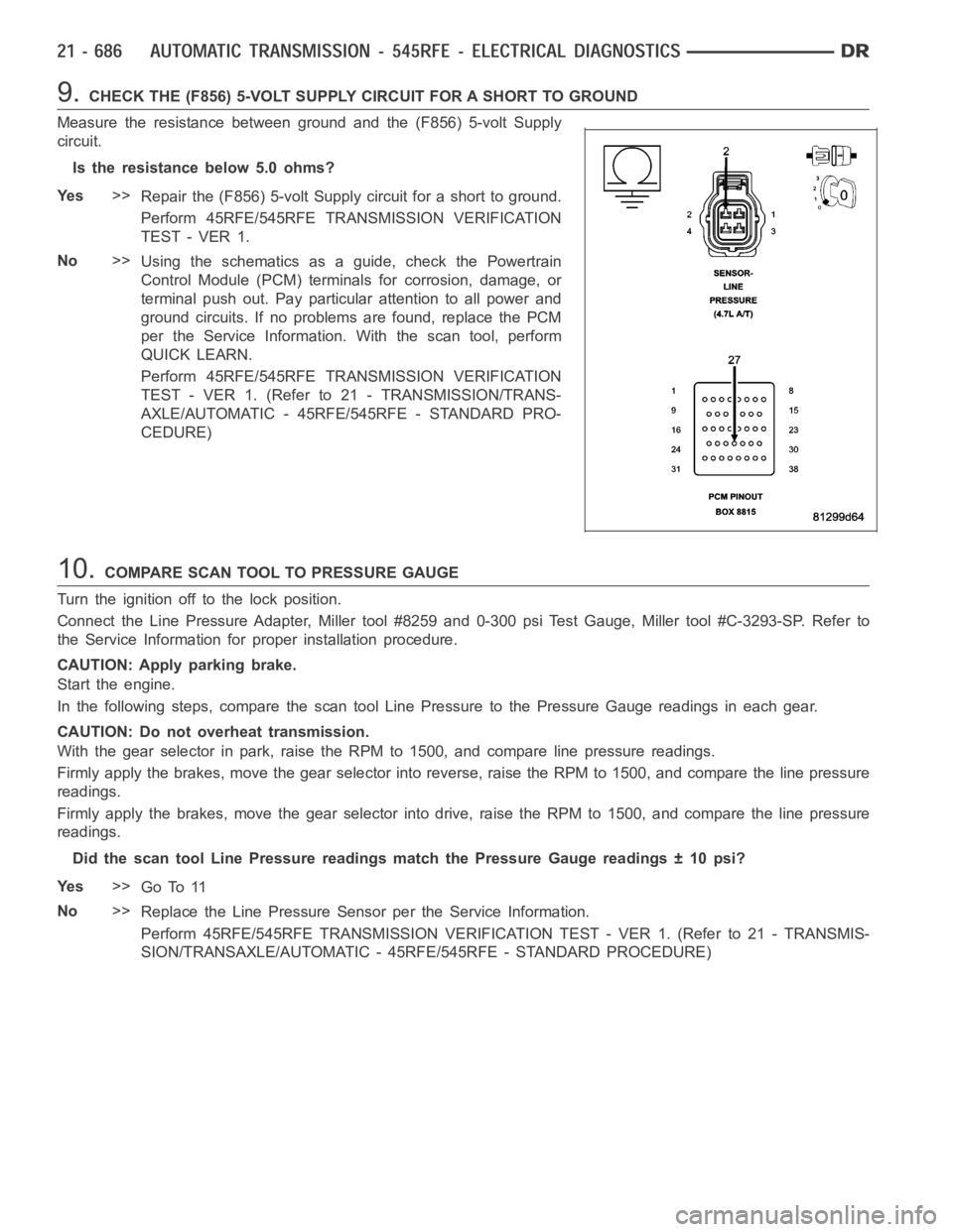
9.CHECK THE (F856) 5-VOLT SUPPLY CIRCUIT FOR A SHORT TO GROUND
Measure the resistance between ground and the (F856) 5-volt Supply
circuit.
Is the resistance below 5.0 ohms?
Ye s>>
Repair the (F856) 5-volt Supply circuit for a short to ground.
Perform 45RFE/545RFE TRANSMISSION VERIFICATION
TEST - VER 1.
No>>
Using the schematics as a guide, check the Powertrain
Control Module (PCM) terminals for corrosion, damage, or
terminal push out. Pay particular attention to all power and
ground circuits. If no problems are found, replace the PCM
per the Service Information.With the scan tool, perform
QUICK LEARN.
Perform 45RFE/545RFE TRANSMISSION VERIFICATION
TEST - VER 1. (Refer to 21 - TRANSMISSION/TRANS-
AXLE/AUTOMATIC - 45RFE/545RFE - STANDARD PRO-
CEDURE)
10.COMPARE SCAN TOOL TO PRESSURE GAUGE
Turn the ignition off to the lock position.
Connect the Line Pressure Adapter, Miller tool #8259 and 0-300 psi Test Gauge, Miller tool #C-3293-SP. Refer to
the Service Information for proper installation procedure.
CAUTION: Apply parking brake.
Start the engine.
In the following steps, compare thescan tool Line Pressure to the PressureGauge readings in each gear.
CAUTION: Do not overheat transmission.
With the gear selector in park, raise the RPM to 1500, and compare line pressure readings.
Firmly apply the brakes, move the gear selector into reverse, raise the RPMto 1500, and compare the line pressure
readings.
Firmly apply the brakes, move the gear selector into drive, raise the RPM to1500, and compare the line pressure
readings.
Did the scan tool Line Pressure readings match the Pressure Gauge readings±10psi?
Ye s>>
Go To 11
No>>
Replace the Line Pressure Sensor per the Service Information.
Perform 45RFE/545RFE TRANSMISSION VERIFICATION TEST - VER 1. (Refer to 21- TRANSMIS-
SION/TRANSAXLE/AUTOMATIC - 45RFE/545RFE - STANDARD PROCEDURE)
Page 3234 of 5267
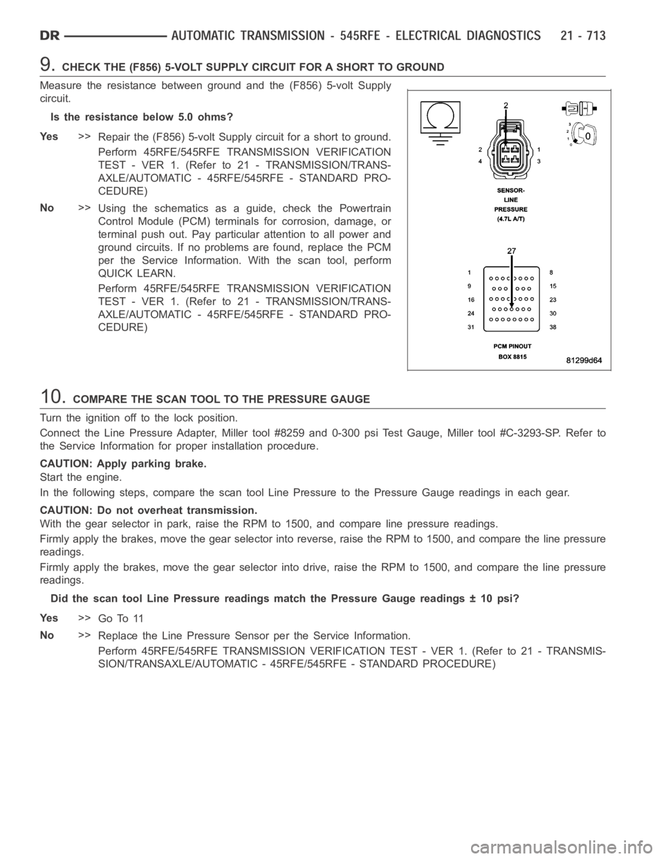
9.CHECK THE (F856) 5-VOLT SUPPLY CIRCUIT FOR A SHORT TO GROUND
Measure the resistance between ground and the (F856) 5-volt Supply
circuit.
Is the resistance below 5.0 ohms?
Ye s>>
Repair the (F856) 5-volt Supply circuit for a short to ground.
Perform 45RFE/545RFE TRANSMISSION VERIFICATION
TEST - VER 1. (Refer to 21 - TRANSMISSION/TRANS-
AXLE/AUTOMATIC - 45RFE/545RFE - STANDARD PRO-
CEDURE)
No>>
Using the schematics as a guide, check the Powertrain
Control Module (PCM) terminals for corrosion, damage, or
terminal push out. Pay particular attention to all power and
ground circuits. If no problems are found, replace the PCM
per the Service Information.With the scan tool, perform
QUICK LEARN.
Perform 45RFE/545RFE TRANSMISSION VERIFICATION
TEST - VER 1. (Refer to 21 - TRANSMISSION/TRANS-
AXLE/AUTOMATIC - 45RFE/545RFE - STANDARD PRO-
CEDURE)
10.COMPARE THE SCAN TOOL TO THE PRESSURE GAUGE
Turn the ignition off to the lock position.
Connect the Line Pressure Adapter, Miller tool #8259 and 0-300 psi Test Gauge, Miller tool #C-3293-SP. Refer to
the Service Information for proper installation procedure.
CAUTION: Apply parking brake.
Start the engine.
In the following steps, compare thescan tool Line Pressure to the PressureGauge readings in each gear.
CAUTION: Do not overheat transmission.
With the gear selector in park, raise the RPM to 1500, and compare line pressure readings.
Firmly apply the brakes, move the gear selector into reverse, raise the RPMto 1500, and compare the line pressure
readings.
Firmly apply the brakes, move the gear selector into drive, raise the RPM to1500, and compare the line pressure
readings.
Did the scan tool Line Pressure readings match the Pressure Gauge readings±10psi?
Ye s>>
Go To 11
No>>
Replace the Line Pressure Sensor per the Service Information.
Perform 45RFE/545RFE TRANSMISSION VERIFICATION TEST - VER 1. (Refer to 21- TRANSMIS-
SION/TRANSAXLE/AUTOMATIC - 45RFE/545RFE - STANDARD PROCEDURE)
Page 3251 of 5267
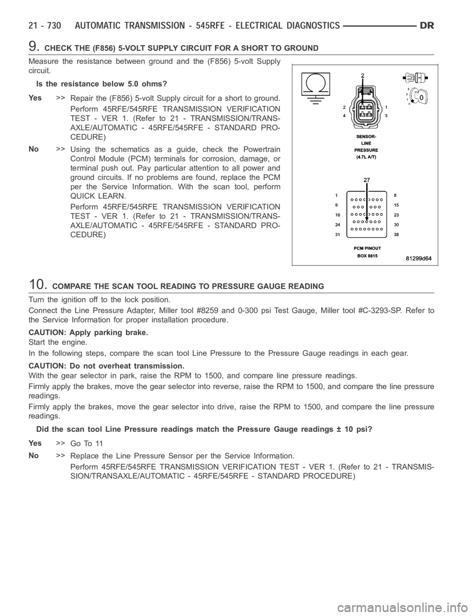
9.CHECK THE (F856) 5-VOLT SUPPLY CIRCUIT FOR A SHORT TO GROUND
Measure the resistance between ground and the (F856) 5-volt Supply
circuit.
Is the resistance below 5.0 ohms?
Ye s>>
Repair the (F856) 5-volt Supply circuit for a short to ground.
Perform 45RFE/545RFE TRANSMISSION VERIFICATION
TEST - VER 1. (Refer to 21 - TRANSMISSION/TRANS-
AXLE/AUTOMATIC - 45RFE/545RFE - STANDARD PRO-
CEDURE)
No>>
Using the schematics as a guide, check the Powertrain
Control Module (PCM) terminals for corrosion, damage, or
terminal push out. Pay particular attention to all power and
ground circuits. If no problems are found, replace the PCM
per the Service Information.With the scan tool, perform
QUICK LEARN.
Perform 45RFE/545RFE TRANSMISSION VERIFICATION
TEST - VER 1. (Refer to 21 - TRANSMISSION/TRANS-
AXLE/AUTOMATIC - 45RFE/545RFE - STANDARD PRO-
CEDURE)
10.COMPARE THE SCAN TOOL READING TO PRESSURE GAUGE READING
Turn the ignition off to the lock position.
Connect the Line Pressure Adapter, Miller tool #8259 and 0-300 psi Test Gauge, Miller tool #C-3293-SP. Refer to
the Service Information for proper installation procedure.
CAUTION: Apply parking brake.
Start the engine.
In the following steps, compare thescan tool Line Pressure to the PressureGauge readings in each gear.
CAUTION: Do not overheat transmission.
With the gear selector in park, raise the RPM to 1500, and compare line pressure readings.
Firmly apply the brakes, move the gear selector into reverse, raise the RPMto 1500, and compare the line pressure
readings.
Firmly apply the brakes, move the gear selector into drive, raise the RPM to1500, and compare the line pressure
readings.
Did the scan tool Line Pressure readings match the Pressure Gauge readings±10psi?
Ye s>>
Go To 11
No>>
Replace the Line Pressure Sensor per the Service Information.
Perform 45RFE/545RFE TRANSMISSION VERIFICATION TEST - VER 1. (Refer to 21- TRANSMIS-
SION/TRANSAXLE/AUTOMATIC - 45RFE/545RFE - STANDARD PROCEDURE)