2006 DODGE RAM SRT-10 lights
[x] Cancel search: lightsPage 2419 of 5267

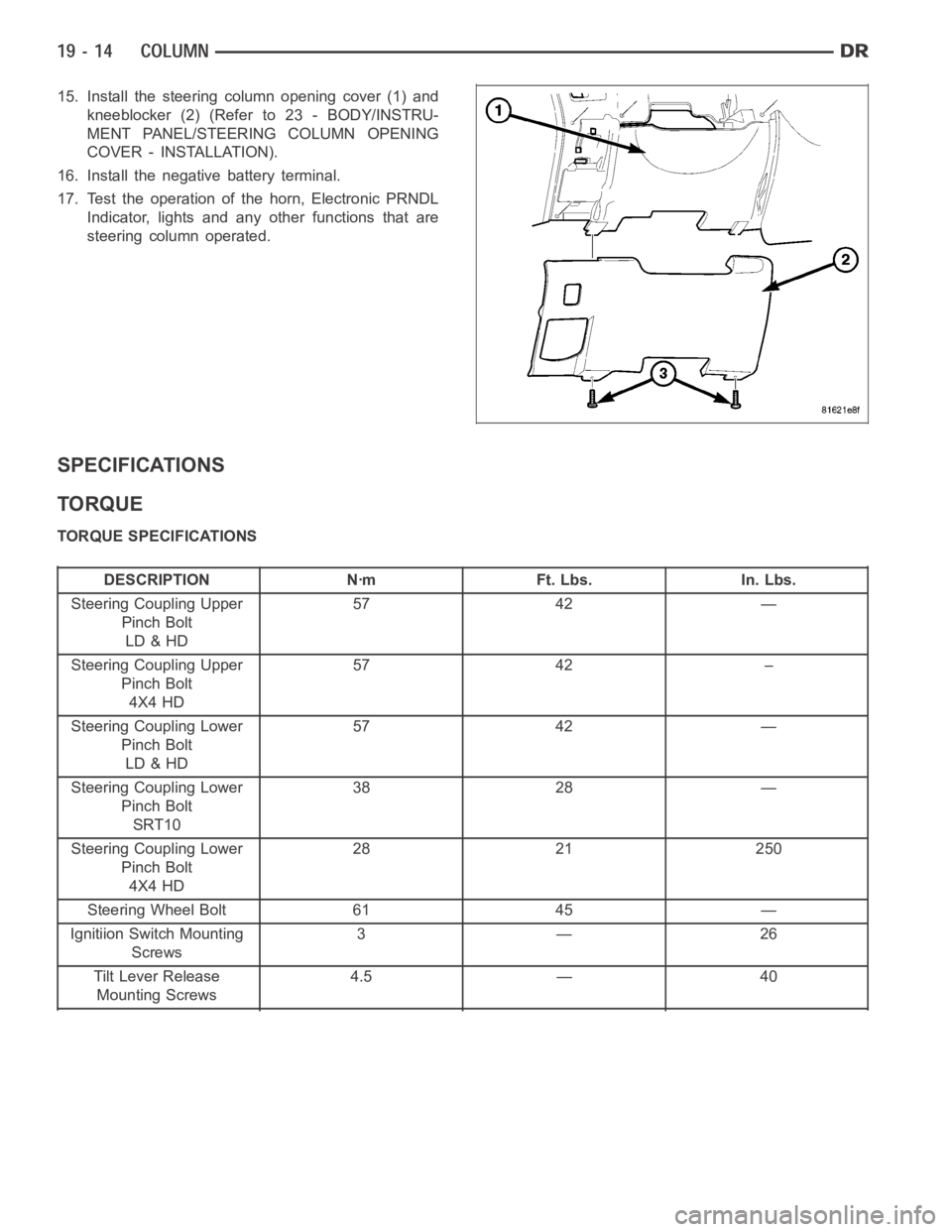
15. Install the steering column opening cover (1) and
kneeblocker (2) (Refer to 23 - BODY/INSTRU-
MENT PANEL/STEERING COLUMN OPENING
COVER - INSTALLATION).
16. Install the negative battery terminal.
17. Test the operation of the horn, Electronic PRNDL
Indicator, lights and any other functions that are
steering column operated.
SPECIFICATIONS
TORQUE
TORQUE SPECIFICATIONS
DESCRIPTION Nꞏm Ft. Lbs. In. Lbs.
Steering Coupling Upper
Pinch Bolt
LD & HD57 42 —
Steering Coupling Upper
Pinch Bolt
4X4 HD57 42 –
Steering Coupling Lower
Pinch Bolt
LD & HD57 42 —
Steering Coupling Lower
Pinch Bolt
SRT1038 28 —
Steering Coupling Lower
Pinch Bolt
4X4 HD28 21 250
Steering Wheel Bolt 61 45 —
Ignitiion Switch Mounting
Screws3—26
Tilt Lever Release
Mounting Screws4.5 — 40
Page 2745 of 5267

4.TRS SENSE CIRCUIT SHORT TO GROUND
Measure the resistance between ground and the identified (T1, T3, T41, or T42) TRS Sense circuit.
Is the resistance below 5.0 ohms?
Ye s>>
Repair the identified (T1, T3, T41, or T42) TRS Sense circuit for a short to ground.
Perform the PRNDL Fault Clearing Procedure – Go To 7
No>>
Go To 5
5.TRS SENSE CIRCUIT SHORT TO OTHER CIRCUITS
Measure the resistance between the identified (T1, T3, T41, or T42) TRS Sense circuit and all other circuits in the
Transmission Solenoid/TRS Assembly harness connector.
Is the resistance below 100k ohms between the identified (T1, T3, T41, or T42) TRS Sense circuit and
any other circuit(s) in the Transmission Solenoid/TRS Assembly harness connector?
Ye s>>
Repair the identified (T1, T3, T41, or T42) TRS Sense circuit for a short to other circuit(s).
Perform the PRNDL Fault Clearing Procedure – Go To 7
No>>
Using the schematics as a guide, check the Powertrain Control Module (PCM)terminals for corrosion,
damage, or terminal push out. Pay particular attention to all power and ground circuits. If no problems
are found, replace the PCM per the Service Information. With the scan tool,perform QUICK LEARN.
Perform the PRNDL Fault Clearing Procedure – Go To 7
6.INTERMITTENT WIRING AND CONNECTORS
The conditions necessary to set the DTC are not present at this time.
Using the schematics as a guide, inspect the wiring and connectors specifictothiscircuit.
Wiggle the wiring and connectors while checking for shorted and open circuits.
With the scan tool, check the DTC EVENT DATA to help identify the conditionsin which the DTC was set.
Were there any problems found?
Ye s>>
Repair as necessary.
Perform the PRNDL Fault Clearing Procedure – Go To 7
No>>
Te s t C o m p l e t e .
7.PRNDL FAULT CLEARING PROCEDURE
With the scan tool, erase Transmission DTCs.
Cycle the ignition off, then start the vehicle.
Firmly apply the brakes and shift into Overdrive.
NOTE: Vehicle must remain in Overdrive for at least 3.0 seconds.
With the brakes firmly applied, shift slowly through all gears (PRNDL) as least three times, pausing momentarily in
each gear.
NOTE: If all the PRNDL lights box individually then the error was cleared.
Shift into park and turn the ignition off to the lock position.
Ignition on, engine not running.
With the scan tool, read Transmission DTCs.
Does the DTC P0706 reset, or do all the PRNDL indicators remain boxed in parkor neutral?
Ye s>>
Return to the symptom list and perform diagnostics for P0706-TRANSMISSION RANGE SENSOR
RATIONALITY.
Go To 1
No>>
Te s t C o m p l e t e .
Perform 42RLE TRANSMISSION VERIFICATION TEST - VER 1. (Refer to 21 - TRANSMISSION/
TRANSAXLE/AUTOMATIC - 42RLE - STANDARD PROCEDURE)
Page 4339 of 5267

BODY
WARNING
SAFETY PRECAUTIONS AND WARNINGS
WARNING: Use an OSHA approved breathing filter when spraying paint or solvents in a confined area. Per-
sonal injury can result.
Avoidprolongedskincontactwithpetroleumoralcohol–basedcleaningsolvents. Personal injury can
result.
Do not stand under a hoisted vehicle that is not properly supported on safety stands. Personal injury can
result.
CAUTION: When holes must be drilled or punched in an inner body panel, verify depth of space to the outer
body panel, electrical wiring, or other components. Damage to vehicle canresult.
Do not weld exterior panels unless combustible material on the interior ofvehicle is removed from the
repair area. Fire or hazardous conditions, can result.
Always have a fire extinguisher ready for use when welding.
Disconnect the negative (-) cable clamp from the battery when servicing electrical components that are
live when the ignition is OFF. Damage to electrical system can result.
Do not use abrasive chemicals or compounds on painted surfaces. Damage to finish can result.
Do not use harsh alkaline based cleaning solvents on painted or upholstered surfaces. Damage to finish
or color can result.
Do not hammer or pound on plastic trim panel when servicing interior trim. Plastic panels can break.
DIAGNOSIS AND TESTING
WAT E R L E A K S
Water leaks can be caused by poor sealing, improper body component alignment, body seam porosity, missing
plugs, or blocked drain holes. Centrifugal and gravitational force can cause water to drip from a location away from
the actual leak point, making leak detection difficult. All body sealing points should be water tight in normal wet-
driving conditions. Water flowing downward from the front of the vehicle should not enter the passenger or luggage
compartment. Moving sealing surfaces will not always seal water tight under all conditions. At times, side glass or
door seals will allow water to enter the passenger compartment during highpressure washing or hard driving rain
(severe) conditions. Overcompensating on door or glass adjustments to stop a water leak that occurs under severe
conditions can cause premature sealwear and excessive closing or latching effort. After completing a repair, water
test vehicle to verify leak has stopped before returning vehicle to use.
VISUAL INSPECTION BEFORE WATER LEAK TESTS
Verify that floor and body plugs are in place, body drains are clear, and body components are properly aligned and
sealed. If component alignment or sealing is necessary, refer to the appropriate section of this group for proper
procedures.
WATER LEAK TESTS
WARNING: Do not use electric shop lights or tools in water test area. Personal injury can result.
When the conditions causing a water leak have been determined, simulate the conditions as closely as possible.
Ifaleakoccurswiththevehicleparkedinasteadylightrain,floodtheleak area with an open-ended garden
hose.
If a leak occurs while driving at highway speeds in a steady rain, test the leak area with a reasonable velocity
stream or fan spray of water. Direct the spray in a direction comparable to actual conditions.
If a leak occurs when the vehicle is parked on an incline, hoist the end or sideofthevehicletosimulatethis
condition. This method can be used when the leak occurs when the vehicle accelerates, stops or turns. If the
leak occurs on acceleration, hoist the front of the vehicle. If the leak occurs when braking, hoist the back of the