2006 DODGE RAM SRT-10 oil capacity
[x] Cancel search: oil capacityPage 3884 of 5267
SERVO-FRONT
DESCRIPTION
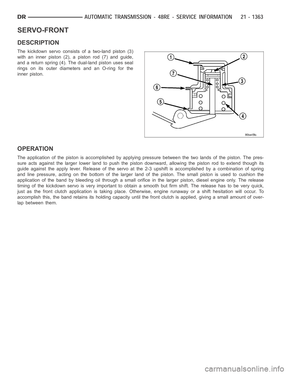
The kickdown servo consists of a two-land piston (3)
with an inner piston (2), a piston rod (7) and guide,
and a return spring (4). The dual-land piston uses seal
rings on its outer diameters and an O-ring for the
inner piston.
OPERATION
The application of the piston is accomplished by applying pressure between the two lands of the piston. The pres-
sure acts against the larger lower land to push the piston downward, allowing the piston rod to extend though its
guide against the apply lever. Release of the servo at the 2-3 upshift is accomplished by a combination of spring
and line pressure, acting on the bottom of the larger land of the piston. Thesmallpistonisusedtocushionthe
application of the band by bleeding oil through a small orifice in the larger piston, diesel engine only. The release
timing of the kickdown servo is very important to obtain a smooth but firm shift. The release has to be very quick,
just as the front clutch application is taking place. Otherwise, engine runaway or a shift hesitation will occur. To
accomplish this, the band retains itsholding capacity until the front clutch is applied, giving a small amount of over-
lap between them.
Page 4331 of 5267
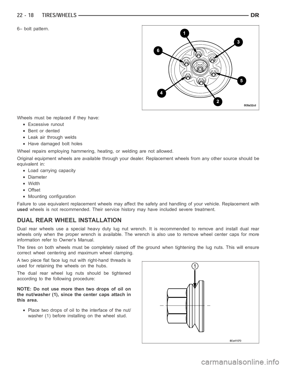
6– bolt pattern.
Wheels must be replaced if they have:
Excessive runout
Bent or dented
Leak air through welds
Have damaged bolt holes
Wheel repairs employing hammering, heating, or welding are not allowed.
Original equipment wheels are available through your dealer. Replacement wheels from any other source should be
equivalent in:
Load carrying capacity
Diameter
Width
Offset
Mounting configuration
Failure to use equivalent replacement wheels may affect the safety and handling of your vehicle. Replacement with
usedwheels is not recommended. Their service history may have included severetreatment.
DUAL REAR WHEELINSTALLATION
Dual rear wheels use a special heavy duty lug nut wrench. It is recommended to remove and install dual rear
wheels only when the proper wrench is available. The wrench is also use to remove wheel center caps for more
information refer to Owner’s Manual.
The tires on both wheels must be completely raised off the ground when tightening the lug nuts. This will ensure
correct wheel centering and maximum wheel clamping.
A two piece flat face lug nut with right-hand threads is
used for retaining the wheels on the hubs.
The dual rear wheel lug nuts should be tightened
according to the following procedure:
NOTE: Do not use more then two drops of oil on
the nut/washer (1), since the center caps attach in
this area.
Place two drops of oil to the interface of the nut/
washer (1) before installing on the wheel stud.
Page 5053 of 5267
ACTUATOR DTC DETECTION TEST — DUAL-ZONE
The Actuator DTC Detection Test:
is actuated with a scan tool.
clears all actuator related DTCs when the test is actuated.
supplements the continuous diagnostics on the actuator drive system.
monitors for shorted actuator circuits allowing service to easily diagnose and troubleshoot up to three simul-
taneous shorts. Shorted actuator circuit faults (XXX Control Circuit High or XXX Control Circuit Low) will only
display after running the Actuator DTC Detection Test.
After repairing each DTC, cycle the ignition switch, and then run the Actuator DTC Detection Test again to ensure
that no new DTCs exist. If multiple DTCs are present, beginning with the passenger blend door, diagnose and repair
all short high faults and then short low faults. When the test returns passed, clear all faults and run the Actuator
Calibration function as a final check of system health.
ACTUATOR DTC DETECTION TEST — SINGLE-ZONE
The Actuator DTC Detection Test:
is actuated with a scan tool.
clears all actuator related DTCs when the test is actuated.
supplements the continuous diagnostics on the actuator drive system.
monitors for shorted actuator circuits allowing service to easily diagnose and troubleshoot up to three simul-
taneous shorts. Shorted actuator circuit faults (XXX Control Circuit High or XXX Control Circuit Low) will only
display after running the Actuator DTC Detection Test.
After repairing each DTC, cycle the ignition switch, and then run the Actuator DTC Detection Test again to ensure
that no new DTCs exist. If multiple DTCs are present, beginning with the common circuit, diagnose and repair all
short high faults and then short low faults. When the test returns passed, clear all faults and run the Actuator Cal-
ibration function as a final check of system health.
A/C PERFORMANCE
The A/C system is designed to provide the passenger compartment with low temperature and low humidity air. The
A/C evaporator, located in the HVAC housing is cooled to temperatures nearthe freezing point. As warm damp air
passes over the fins of the A/C evaporator, the air transfers its heat to therefrigerant in the evaporator coils and the
moisture in the air condenses on the evaporator fins. During periods of high heat and humidity, an A/C system will
be more effective in the Recirculation mode (max-A/C). With the system in the Recirculation mode, only air from the
passenger compartment passes through the A/C evaporator. As the passenger compartment air dehumidifies, the
A/C system performance levels rise.
Humidity has an important bearing on the temperature of the air delivered to the interior of the vehicle. It is impor-
tant to understand the effect that humidity has on the performance of the A/C system. When humidity is high, the
A/C evaporator has to perform a double duty. It must lower the air temperature, and it must lower the temperature
of the moisture in the air that condenses on the evaporator fins. Condensing the moisture in the air transfers heat
energy into the evaporator fins and coils. This reduces the amount of heat the A/C evaporator can absorb from the
air. High humidity greatly reduces the ability of the A/C evaporator to lower the temperature of the air.
However, evaporator capacity used to reduce the amount of moisture in the air is not wasted. Wringing some of the
moisture out of the air entering the vehicle adds to the comfort of the passengers. Although, an owner may expect
too much from their A/C system on humid days. A performance test is the best way to determine whether the sys-
tem is performing up to design standards. This test also provides valuableclues as to the possible cause of trouble
with the A/C system. The ambient air temperature in the location where the vehicle will be tested must be a mini-
mum of 21° C (70° F) for this test.
A/C PERFORMANCE TEST
WARNING: Refer to the applicable warnings and cautions for this system before performing the following
operation (Refer to 24 - HEATING & AIR CONDITIONING/PLUMBING - WARNINGS) and (Refer to 24 - HEAT-
ING & AIR CONDITIONING/PLUMBING - CAUTIONS). Failure to follow the warnings and cautions could result
in possible personal injury or death.
Page 5057 of 5267
Improper heater hose routing.
Plugged heater hoses or supply and return ports at the cooling system connections.
Plugged heater core.
If proper coolant flow through the cooling system is verified, and heater outlet air temperature is low, a mechanical
problem may exist.
MECHANICAL PROBLEMS
Possible locations or causes of insufficient heat due to mechanical problems are as follows:
Obstructed cowl air intake.
Obstructed heater system outlets.
Blend-air door(s) or actuator(s) not functioning properly.
Faulty blower motor system
Faulty A/C-heater control
TEMPERATURE CONTROL
If the heater outlet air temperature cannot be adjusted with the temperature control on the A/C-heater control, the
following could require service:
Faulty A/C-heater control.
Faulty blend door actuator(s).
Faulty, obstructed or improperly installed blend-air door.
Faulty related wiring harness or connectors.
Improper engine coolant temperature.
SPECIFICATIONS
A/C SYSTEM
Item Description Notes
A/C Compressor Denso 10S17 (3.7L/4.7L/5.7L/8.3L
engines)ND-8 PAG oil
Visteon HS-18 (5.9L engine) VC-46 PAG oil
Freeze–up Control Evaporator Temperature Sensor A/C evaporator mounted
High psi Control A/C pressure transducer A/C discharge line mounted
Refrigerant Charge Capacity Refer to the A/C Underhood
Specification Label located in the
engine compartment.R134a refrigerant
A/C Clutch Field Coil Draw 3.2 - 3.3 amps @ 12V ± 0.5V @
21° C (70° F)3.7L/4.7L/5.7L/8.3L engines
3.1 - 4 amps @ 12V ± 0.5V @ 21°
C(70°F)5.9L engine
A/C Clutch Air Gap 0.35 - 0.60 mm (0.014 - 0.024 in.) 3.7L/4.7L/5.7L/8.3L engines
0.35 - 0.75 mm (0.014 - 0.030 in.) 5.9L engine
TORQUE
Page 5127 of 5267
PLUMBING
DESCRIPTION
The A/C refrigerant lines and hoses are used to carry the refrigerant between the various A/C system components.
The refrigerant lines and hoses for the R-134a system on this vehicle consist of a barrier-hose design with a nylon
tube sandwiched between rubber layers. The nylon tube helps to contain theR-134a refrigerant, which has a
smaller molecular structure than R-12 refrigerant. The ends of the refrigerant lines are made from lightweight alu-
minum or steel, and commonly use braze-less fittings.
Any kinks or sharp bends in the refrigerant lines and hoses will reduce the capacity of the entire A/C system and
can reduce the flow of refrigerant in the system. The radius of all bends in the flexible hose refrigerant lines should
be at least ten times the diameter of the hose and the refrigerant lines should be routed so they are at least 80
millimeters (3 inches) away from the exhaust manifold(s) and exhaust pipe(s).
OPERATION
High pressures are produced in the refrigerant system when the A/C compressor is operating. Extreme care must
be exercised to make sure that each of the refrigerant system connections is pressure-tight and leak free. It is a
good practice to inspect all flexible hose refrigerant lines at least oncea year to make sure they are in good con-
dition and properly routed.
The refrigerant lines and hoses are coupled to other A/C system componentswith block-type fittings. An O-ring seal,
or a flat steel gasket with an integral O-ring (dual plane seal), is used to mate the refrigerant line fittings with A/C
system components to ensure the integrity of the refrigerant system.
The refrigerant lines and hoses cannot be repaired and, if faulty or damaged, they must be replaced.
WARNING
WARNING: The A/C system contains refrigerant under high pressure. Repairs should only be performed by
qualified service personnel. Severe personal injury or death may result from improper service procedures.
WARNING: Avoid breathing the refrigerant and refrigerant oil vapor or mist. Exposure may irritate the eyes,
nose, and/or throat. Wear eye protection when servicing the A/C refrigerant system. Serious eye injury can
result from direct contact with the refrigerant. If eye contact occurs, seek medical attention immediately.
WARNING: Do not expose the refrigerant to open flame. Poisonous gas is createdwhenrefrigerantis
burned. An electronic leak detector is recommended. Severe personal injury or death may result from
improper service procedures.
WARNING: If accidental system discharge occurs, ventilate the work area before resuming service. Large
amounts of refrigerant released in a closed work area will displace the oxygen and cause suffocation and
death.
WARNING: The evaporation rate of R-134a refrigerant at average temperature and altitude is extremely high.
As a result, anything that comes in contact with the refrigerant will freeze. Always protect the skin or del-
icate objects from direct contact with the refrigerant.
WARNING: The R-134a service equipment or the vehicle refrigerant system should not be pressure tested or
leak tested with compressed air. Some mixtures of air and R-134a have been shown to be combustible at
elevated pressures. These mixtures are potentially dangerous, and may result in fire or explosion causing
property damage, personal injury or death.
Page 5188 of 5267
OIL-A/C REFRIGERANT
DESCRIPTION
The refrigerant oil used in R-134a refrigerant systems is a synthetic-based, polyalkylene glycol (PAG), wax-free
lubricant. Mineral-based R-12 refrigerant oils are not compatible with PAG oils, and should never be introduced to
an R-134a refrigerant system.
There are different PAG oils available, and each contains a different additive package. Useonlyrefrigerant oil of the
same type as recommended to service the refrigerant system (always refer to the specification tagincluded with
the replacement A/C compressor or the A/C Underhood Specification Label located in the engine compartment).
The Denso 10S17 A/C compressor used in this vehicle when equipped with the 3.7L, 4.7L, 5.7L or 8.3L engine is
designed to use ND-8 PAG refrigerant oil. Use only this type of refrigerantoil when servicing the A/C compressor for
these engines.
The Visteon HS-18 A/C compressor used in this vehicle when equipped with 5.9L diesel engine is designed to use
VC-46 PAG refrigerant oil. Use only this type of refrigerant oil when servicing this A/C compressor.
OPERATION
After performing any refrigerant recovery or recycling operation, always replenish the refrigerant system with the
same amount of the recommended refrigerant oil as was removed. Too little refrigerant oil can cause A/C compres-
sor damage, and too much can reduce A/C system performance.
PAG refrigerant oil is more hygroscopic than mineral oil, and will absorb any moisture it comes into contact with,
even moisture in the air. The PAG oil container should always be kept tightly capped until it is ready to be used.
After use, recap the oil container immediately to prevent moisture contamination.
STANDARD PROCEDURE
REFRIGERANT OIL LEVEL
When an A/C system is assembled at the factory, all components except the A/C compressor are refrigerant oil free.
After the refrigerant system has been charged and operated, the refrigerant oil in the A/C compressor is dispersed
throughout the refrigerant system. The accumulator, A/C evaporator, A/Ccondenser and the A/C compressor will
each retain a significant amount of the needed refrigerant oil.
It is important to have the correct amount of refrigerant oil in the A/C system. This ensures proper lubrication of the
A/C compressor. Too little oil will result in damage to the A/C compressor,while too much oil will reduce the cooling
capacity of the A/C system and consequently result in higher discharge airtemperatures.
CAUTION: The refrigerant oil in the R-134a A/C system is unique depending on the A/C compressor used.
Use only PAG oils that are designed to work with R-134a refrigerant and the A/C compressor in the vehicle.
Always refer to the A/C Underhood Specification Label for the correct oil designation. The oil container
should be kept tightly capped until it is ready for use and then tightly capped after use to prevent contam-
ination from dirt and moisture. Refrigerant oil will quickly absorb any moisture it comes in contact with,
therefore, special effort must be used to keep all R-134a system components moisture-free. Moisture in the
refrigerant oil is very difficult toremove and will cause a reliability problem with the A/C compressor.
NOTE: Most reclaim/recycling equipment will measure the lubricant beingremoved during recovery. This
amount of lubricant should be added back into the system. Refer to the reclaim/recycling equipment man-
ufacturers instructions.
It will not be necessary to check the oil level in the A/C compressor or to addoil, unless there has been an oil loss.
An oil loss may occur due to a rupture or leak from a refrigerant line, a connector fitting, a component, or a com-
ponent seal. If a leak occurs, add 30 milliliters (1 fluid ounce) of refrigerant oil to the refrigerant system after the
repair has been made. Refrigerant oil loss will be evident at the leak pointby the presence of a wet, shiny surface
around the leak.
Refrigerant oil must be added when an accumulator, A/C evaporator or A/C condenser is replaced. See the Refrig-
erant Oil Capacities chart. When an A/C compressor is replaced, the refrigerant oil must be drained from the old