2006 DODGE RAM SRT-10 service interval
[x] Cancel search: service intervalPage 1274 of 5267
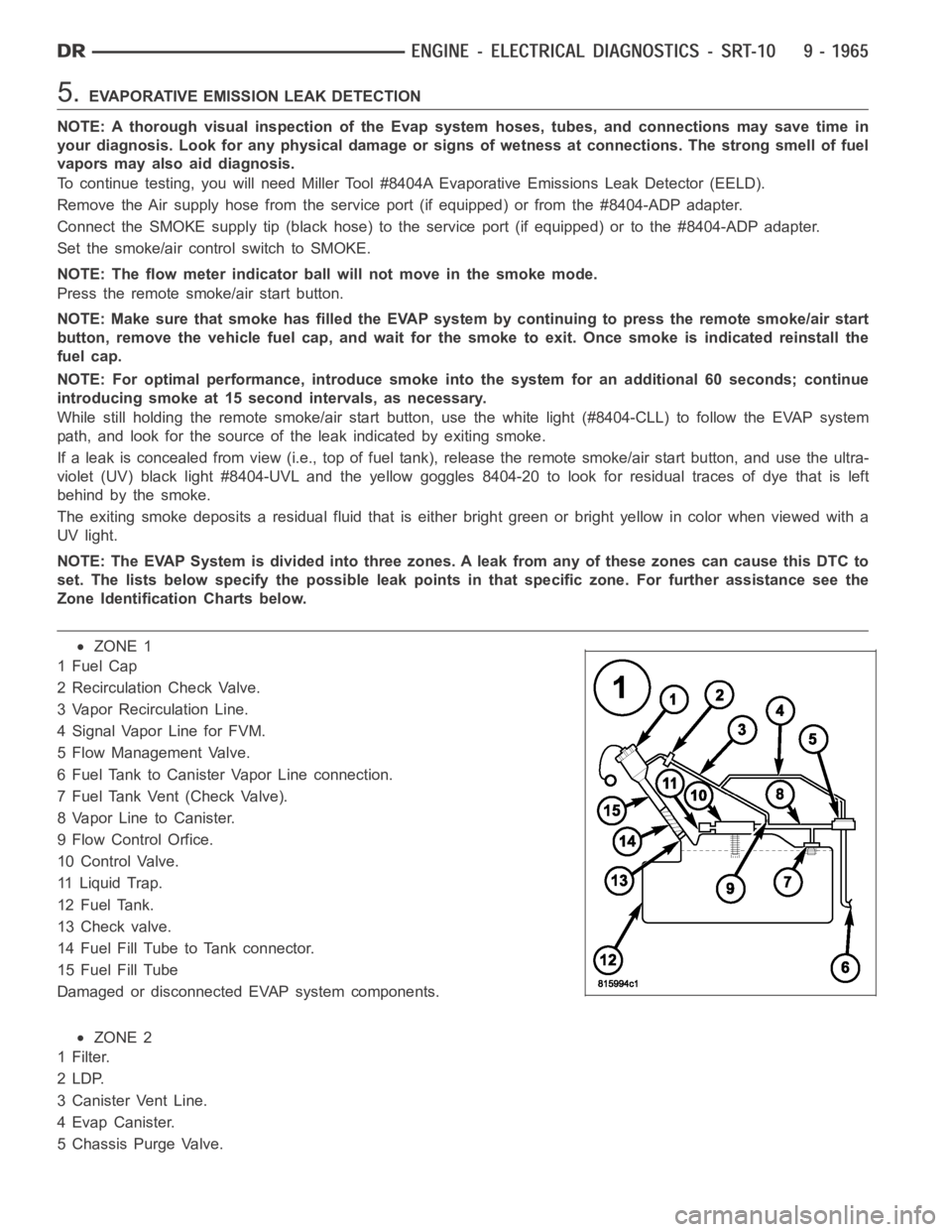
5.EVAPORATIVE EMISSION LEAK DETECTION
NOTE: A thorough visual inspection of the Evap system hoses, tubes, and connections may save time in
your diagnosis. Look for any physical damage or signs of wetness at connections. The strong smell of fuel
vapors may also aid diagnosis.
To continue testing, you will need Miller Tool #8404A Evaporative Emissions Leak Detector (EELD).
Remove the Air supply hose from the service port (if equipped) or from the #8404-ADP adapter.
Connect the SMOKE supply tip (black hose) to the service port (if equipped)or to the #8404-ADP adapter.
Set the smoke/air control switch to SMOKE.
NOTE: The flow meter indicator ball will not move in the smoke mode.
Press the remote smoke/air start button.
NOTE: Make sure that smoke has filled the EVAP system by continuing to presstheremotesmoke/airstart
button, remove the vehicle fuel cap, and wait for the smoke to exit. Once smoke is indicated reinstall the
fuel cap.
NOTE: For optimal performance, introduce smoke into the system for an additional 60 seconds; continue
introducing smoke at 15 second intervals, as necessary.
While still holding the remote smoke/air start button, use the white light(#8404-CLL) to follow the EVAP system
path, and look for the source of the leak indicated by exiting smoke.
If a leak is concealed from view (i.e., top of fuel tank), release the remotesmoke/air start button, and use the ultra-
violet (UV) black light #8404-UVL and the yellow goggles 8404-20 to look for residual traces of dye that is left
behind by the smoke.
The exiting smoke deposits a residual fluid that is either bright green or bright yellow in color when viewed with a
UV light.
NOTE: The EVAP System is divided into three zones. A leak from any of these zonescancausethisDTCto
set. The lists below specify the possible leak points in that specific zone. For further assistance see the
Zone Identification Charts below.
ZONE 1
1FuelCap
2 Recirculation Check Valve.
3 Vapor Recirculation Line.
4 Signal Vapor Line for FVM.
5 Flow Management Valve.
6 Fuel Tank to Canister Vapor Line connection.
7 Fuel Tank Vent (Check Valve).
8 Vapor Line to Canister.
9 Flow Control Orfice.
10 Control Valve.
11 Liquid Trap.
12 Fuel Tank.
13 Check valve.
14 Fuel Fill Tube to Tank connector.
15 Fuel Fill Tube
Damaged or disconnected EVAP system components.
ZONE 2
1Filter.
2LDP.
3 Canister Vent Line.
4EvapCanister.
5 Chassis Purge Valve.
Page 1284 of 5267
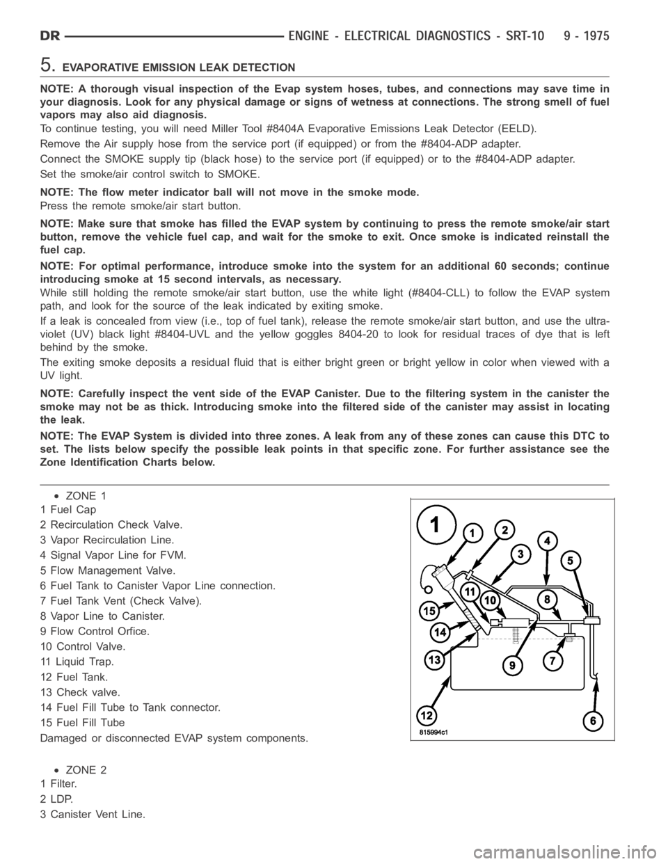
5.EVAPORATIVE EMISSION LEAK DETECTION
NOTE: A thorough visual inspection of the Evap system hoses, tubes, and connections may save time in
your diagnosis. Look for any physical damage or signs of wetness at connections. The strong smell of fuel
vapors may also aid diagnosis.
To continue testing, you will need Miller Tool #8404A Evaporative Emissions Leak Detector (EELD).
Remove the Air supply hose from the service port (if equipped) or from the #8404-ADP adapter.
Connect the SMOKE supply tip (black hose) to the service port (if equipped)or to the #8404-ADP adapter.
Set the smoke/air control switch to SMOKE.
NOTE: The flow meter indicator ball will not move in the smoke mode.
Press the remote smoke/air start button.
NOTE: Make sure that smoke has filled the EVAP system by continuing to presstheremotesmoke/airstart
button, remove the vehicle fuel cap, and wait for the smoke to exit. Once smoke is indicated reinstall the
fuel cap.
NOTE: For optimal performance, introduce smoke into the system for an additional 60 seconds; continue
introducing smoke at 15 second intervals, as necessary.
While still holding the remote smoke/air start button, use the white light(#8404-CLL) to follow the EVAP system
path, and look for the source of the leak indicated by exiting smoke.
If a leak is concealed from view (i.e., top of fuel tank), release the remotesmoke/air start button, and use the ultra-
violet (UV) black light #8404-UVL and the yellow goggles 8404-20 to look for residual traces of dye that is left
behind by the smoke.
The exiting smoke deposits a residual fluid that is either bright green or bright yellow in color when viewed with a
UV light.
NOTE: Carefully inspect the vent side of the EVAP Canister. Due to the filtering system in the canister the
smoke may not be as thick. Introducing smoke into the filtered side of the canister may assist in locating
the leak.
NOTE: The EVAP System is divided into three zones. A leak from any of these zonescancausethisDTCto
set. The lists below specify the possible leak points in that specific zone. For further assistance see the
Zone Identification Charts below.
ZONE 1
1FuelCap
2 Recirculation Check Valve.
3 Vapor Recirculation Line.
4 Signal Vapor Line for FVM.
5 Flow Management Valve.
6 Fuel Tank to Canister Vapor Line connection.
7 Fuel Tank Vent (Check Valve).
8 Vapor Line to Canister.
9 Flow Control Orfice.
10 Control Valve.
11 Liquid Trap.
12 Fuel Tank.
13 Check valve.
14 Fuel Fill Tube to Tank connector.
15 Fuel Fill Tube
Damaged or disconnected EVAP system components.
ZONE 2
1Filter.
2LDP.
3 Canister Vent Line.
Page 1598 of 5267
OIL
STANDARD PROCEDURE - ENGINE OIL SERVICE
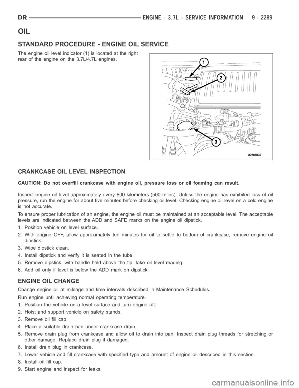
The engine oil level indicator (1) is located at the right
rear of the engine on the 3.7L/4.7L engines.
CRANKCASE OIL LEVEL INSPECTION
CAUTION: Do not overfill crankcase with engine oil, pressure loss or oil foaming can result.
Inspect engine oil level approximately every 800 kilometers (500 miles).Unless the engine has exhibited loss of oil
pressure, run the engine for about five minutes before checking oil level.Checking engine oil level on a cold engine
is not accurate.
To ensure proper lubrication of an engine, the engine oil must be maintained at an acceptable level. The acceptable
levels are indicated between the ADD and SAFE marks on the engine oil dipstick.
1. Position vehicle on level surface.
2. With engine OFF, allow approximately ten minutes for oil to settle to bottom of crankcase, remove engine oil
dipstick.
3. Wipe dipstick clean.
4. Install dipstick and verify it is seated in the tube.
5. Remove dipstick, with handle held above the tip, take oil level reading.
6. Add oil only if level is below the ADD mark on dipstick.
ENGINE OIL CHANGE
Change engine oil at mileage and time intervals described in Maintenance Schedules.
Run engine until achieving normal operating temperature.
1. Position the vehicle on a level surface and turn engine off.
2. Hoist and support vehicle on safety stands.
3. Remove oil fill cap.
4. Place a suitable drain pan under crankcase drain.
5. Remove drain plug from crankcase and allow oil to drain into pan. Inspectdrain plug threads for stretching or
other damage. Replace drain plug if damaged.
6. Install drain plug in crankcase.
7. Lower vehicle and fill crankcase with specified type and amount of engine oil described in this section.
8. Install oil fill cap.
9. Start engine and inspect for leaks.
Page 1723 of 5267
OIL
STANDARD PROCEDURE - ENGINE OIL SERVICE
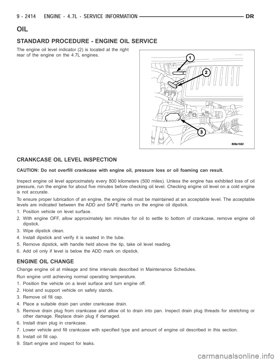
The engine oil level indicator (2) is located at the right
rear of the engine on the 4.7L engines.
CRANKCASE OIL LEVEL INSPECTION
CAUTION: Do not overfill crankcase with engine oil, pressure loss or oil foaming can result.
Inspect engine oil level approximately every 800 kilometers (500 miles).Unless the engine has exhibited loss of oil
pressure, run the engine for about five minutes before checking oil level.Checking engine oil level on a cold engine
is not accurate.
To ensure proper lubrication of an engine, the engine oil must be maintained at an acceptable level. The acceptable
levels are indicated between the ADD and SAFE marks on the engine oil dipstick.
1. Position vehicle on level surface.
2. With engine OFF, allow approximately ten minutes for oil to settle to bottom of crankcase, remove engine oil
dipstick.
3. Wipe dipstick clean.
4. Install dipstick and verify it is seated in the tube.
5. Remove dipstick, with handle held above the tip, take oil level reading.
6. Add oil only if level is below the ADD mark on dipstick.
ENGINE OIL CHANGE
Change engine oil at mileage and time intervals described in Maintenance Schedules.
Run engine until achieving normal operating temperature.
1. Position the vehicle on a level surface and turn engine off.
2. Hoist and support vehicle on safety stands.
3. Remove oil fill cap.
4. Place a suitable drain pan under crankcase drain.
5. Remove drain plug from crankcase and allow oil to drain into pan. Inspectdrain plug threads for stretching or
other damage. Replace drain plug if damaged.
6. Install drain plug in crankcase.
7. Lower vehicle and fill crankcase with specified type and amount of engine oil described in this section.
8. Install oil fill cap.
9. Start engine and inspect for leaks.
Page 1877 of 5267
OIL
STANDARD PROCEDURE - ENGINE OIL SERVICE
The engine oil level indicator is located at the left hand of the engine on the 5.7L engines.
CRANKCASE OIL LEVEL INSPECTION
CAUTION: Do not overfill crankcase with engine oil, pressure loss or oil foaming can result.
Inspect engine oil level approximately every 800 kilometers (500 miles).Unless the engine has exhibited loss of oil
pressure, run the engine for about ten minutes before checking oil level. Checking engine oil level on a cold engine
is not accurate.
To ensure proper lubrication of an engine, the engine oil must be maintained at an acceptable level. The acceptable
levels are indicated between the ADD and SAFE marks on the engine oil dipstick.
1. Position vehicle on level surface.
2. With engine OFF, allow approximately five minutes for oil to settle to bottom of crankcase, remove engine oil
dipstick.
3. Wipe dipstick clean.
4. Install dipstick and verify it is seated in the tube.
5. Remove dipstick, with handle held above the tip, take oil level reading.
6. Add oil only if level is below the ADD mark on dipstick.
ENGINE OIL CHANGE
Change engine oil at mileage and time intervals described in Maintenance Schedules (Refer to LUBRICATION &
MAINTENANCE/MAINTENANCESCHEDULES - DESCRIPTION).
Run engine until achieving normal operating temperature.
1. Position the vehicle on a level surface and turn engine off.
2. Hoist and support vehicle on safety stands.
3. Remove oil fill cap.
4. Place a suitable drain pan under crankcase drain.
5. Remove drain plug from crankcase and allow oil to drain into pan. Inspectdrain plug threads for stretching or
other damage. Replace drain plug if damaged.
6. Install drain plug in crankcase. Torque to 34 Nꞏm ( 25 ft. lbs.).
7. Lower vehicle and fill crankcase with specified type and amount of engine oil described in this section.
8. Install oil fill cap.
9. Start engine and inspect for leaks.
10. Stop engine and inspect oil level.
USED ENGINE OIL DISPOSAL
Care should be exercised when disposing used engine oil after it has been drained from a vehicle engine. Refer to
the WARNING at beginning of this section.
Page 2002 of 5267
OIL
STANDARD PROCEDURE
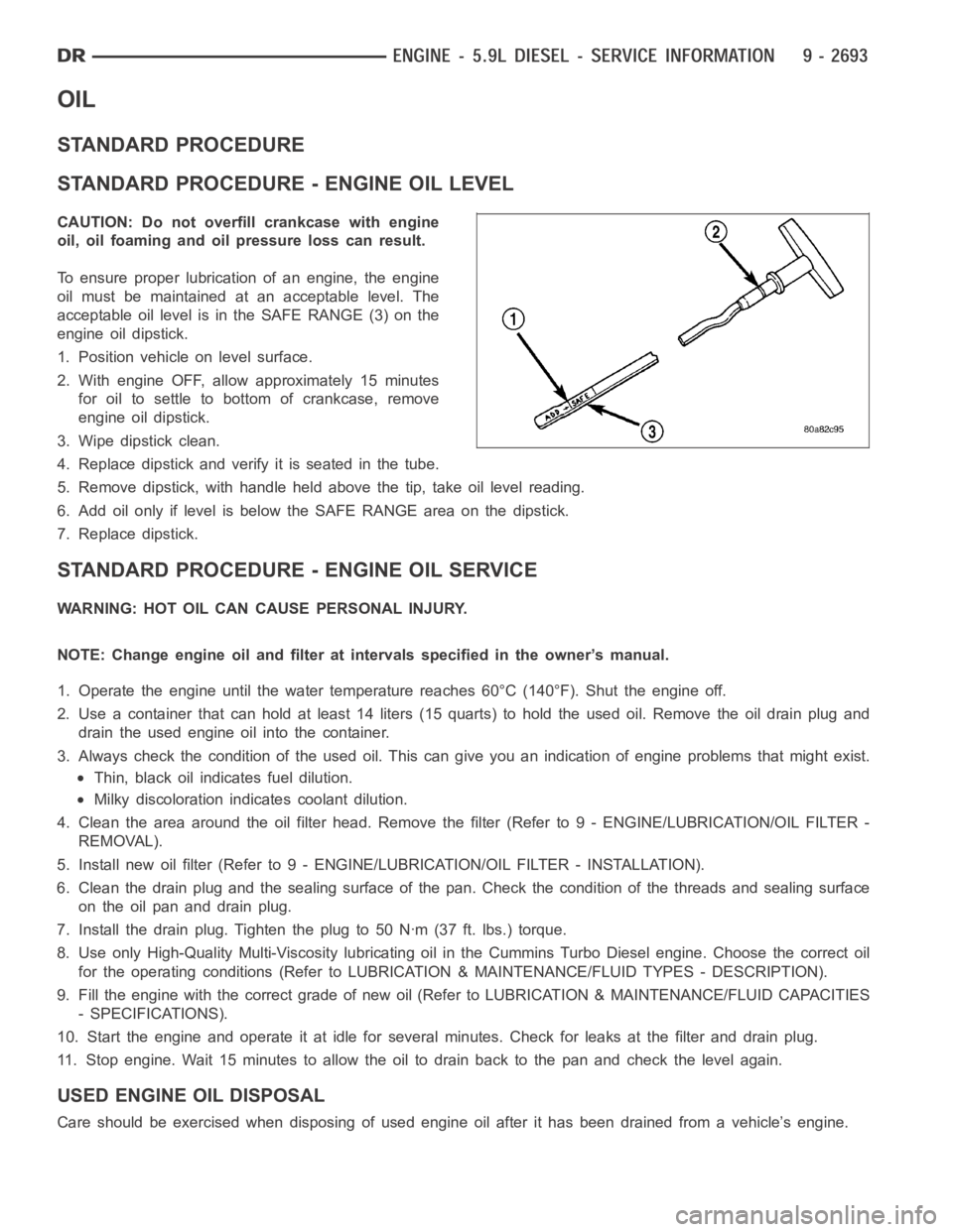
STANDARD PROCEDURE - ENGINE OIL LEVEL
CAUTION: Do not overfill crankcase with engine
oil, oil foaming and oil pressure loss can result.
To ensure proper lubrication of an engine, the engine
oil must be maintained at an acceptable level. The
acceptable oil level is in the SAFE RANGE (3) on the
engine oil dipstick.
1. Position vehicle on level surface.
2. With engine OFF, allow approximately 15 minutes
for oil to settle to bottom of crankcase, remove
engine oil dipstick.
3. Wipe dipstick clean.
4. Replace dipstick and verify it is seated in the tube.
5. Remove dipstick, with handle held above the tip, take oil level reading.
6. Add oil only if level is below the SAFE RANGE area on the dipstick.
7. Replace dipstick.
STANDARD PROCEDURE - ENGINE OIL SERVICE
WARNING: HOT OIL CAN CAUSE PERSONAL INJURY.
NOTE: Change engine oil and filter at intervals specified in the owner’s manual.
1. Operate the engine until the water temperature reaches 60°C (140°F). Shut the engine off.
2. Use a container that can hold at least 14 liters (15 quarts) to hold the used oil. Remove the oil drain plug and
drain the used engine oil into the container.
3. Always check the condition of the used oil. This can give you an indication of engine problems that might exist.
Thin, black oil indicates fuel dilution.
Milky discoloration indicates coolant dilution.
4. Clean the area around the oil filter head. Remove the filter (Refer to 9 - ENGINE/LUBRICATION/OIL FILTER -
REMOVAL).
5. Install new oil filter (Refer to 9 - ENGINE/LUBRICATION/OIL FILTER - INSTA L L AT I O N ) .
6. Clean the drain plug and the sealing surface of the pan. Check the condition of the threads and sealing surface
on the oil pan and drain plug.
7. Install the drain plug. Tighten the plug to 50 Nꞏm (37 ft. lbs.) torque.
8. Use only High-Quality Multi-Viscosity lubricating oil in the Cummins Turbo Diesel engine. Choose the correct oil
for the operating conditions (Refer to LUBRICATION & MAINTENANCE/FLUID TYPES - DESCRIPTION).
9. Fill the engine with the correct grade of new oil (Refer to LUBRICATION & MAINTENANCE/FLUID CAPACITIES
- SPECIFICATIONS).
10. Start the engine and operate it at idle for several minutes. Check for leaks at the filter and drain plug.
11. Stop engine. Wait 15 minutes to allow the oil to drain back to the pan and check the level again.
USED ENGINE OIL DISPOSAL
Care should be exercised when disposing of used engine oil after it has beendrained from a vehicle’s engine.
Page 2343 of 5267
Fuel enters the system from the electric fuel transfer (lift) pump, which is located inside of the fuel tank and attached
to the fuel tank module (the fuel transfer pump is no longer attached to the engine). Fuel is forced through the fuel
filter element and then enters the Fuel Pump/Gear Pump, which is attached to the rear of the fuel injection pump.
The Fuel Pump/Gear Pump is a low-pressure pump and produce pressures ranging from 551.5 kpa (80 psi) to 1241
kpa (180) psi. Fuel then enters the fuel injection pump. Low pressure fuel is then supplied to the FCA (Fuel Control
Actuator).
The FCA is an electronically controlled solenoid valve. The ECM controls the amount of fuel that enters the high-
pressure pumping chambers by opening and closing the FCA based on a demanded fuel pressure. The FPS (Fuel
Pressure Sensor) on the fuel rail monitors the actual fuel pressure and provides it as an input to the ECM. When
the actuator is opened, the maximum amount of fuel is being supplied to the fuel injection pump. Any fuel that does
not enter the injection pump is directed to the overflow valve. The overflow valve regulates how much excess fuel
is used for lubrication of the pump and how much is returned to the tank through the drain manifold.
Fuel entering the injection pump is pressurized to between 300-1600 bar (4351-23,206 psi) by three radial pumping
chambers. The pressurized fuel is then supplied to the fuel rail.
STANDARD PROCEDURE
WATER DRAINING AT FUEL FILTER
Refer to Fuel Filter/Water Separatorremoval/installation for procedures.
CLEANING FUEL SYSTEM PARTS
CAUTION: Cleanliness cannot be overemphasized when handling or replacingdieselfuelsystemcompo-
nents. This especially includes the fuel injectors, high-pressure fuel lines and fuel injection pump. Very tight
tolerances are used with these parts. Dirt contamination could cause rapid part wear and possible plugging
of fuel injector nozzle tip holes. This in turn could lead to possible engine misfire. Always wash/clean any
fuel system component thoroughly before disassembly and then air dry. Capor cover any open part after
disassembly. Before assembly, examine each part for dirt, grease or othercontaminants and clean if nec-
essary. When installing new parts, lubricate them with clean engine oil orclean diesel fuel only.
FUEL SYSTEM PRIMING
A certain amount of air becomes trappedin the fuel system when fuel system components on the supply and/or
high-pressure side are serviced or replaced. Fuel system priming is accomplished using the electric fuel transfer (lift)
pump.
Servicing or replacing fuel system components will not require fuel systempriming.
The fuel transfer (lift) pump is self-priming: When the key is first turnedon (without cranking engine), the pump
operates for approximately 1 to 2 second and then shuts off (Note: When ambient temperatures are cold enough to
cause the intake air heaters to operate, the fuel lift pump will operate during the entire intake air pre-heat cycle).
The pump will also operate for up to 25 seconds after the starter is quickly engaged, and then disengaged without
allowing the engine to start. The pump shuts off immediately if the key is onand the engine stops running.
1. Turn key to CRANK position and quickly release key to ON position before engine starts. This will operate fuel
transfer pump for approximately 25 seconds.
2. Crank engine. If the engine does not start after 25 seconds, turn key to OFF position, and leave it off for at least
5 seconds. Repeat previous step until engine starts.
3. Fuel system priming is now completed.
4. Attempt to start engine. If engine will not start, proceed to following steps.When engine does start, it may run
erratically and be noisy for a few minutes. This is a normal condition.
CAUTION: Do not engage the starter motor for more than 30 seconds at a time. Allow two minutes between
cranking intervals.
5. Perform previous fuel priming procedure steps using fuel transfer pump. Be sure fuel is present at fuel tank.
6. Crank the engine for 30 seconds at a time to allow fuel system to prime.
Page 3432 of 5267
FLUID AND FILTER REPLACEMENT
For proper service intervals (Refer to LUBRICATION & MAINTENANCE/MAINTENANCE SCHEDULES - DESCRIP-
TION).
REMOVAL
1. Hoist and support vehicle on safety stands.
2. Place a large diameter shallow drain pan beneath the transmission pan.
3. Remove bolts holding front and sides of pan to transmission.
4. Loosen bolts holding rear of pan to transmission.
5. Slowly separate front of pan away from transmission allowing the fluid to drain into drain pan.
6. Hold up pan and remove remaining bolts holding pan to transmission.
7. While holding pan level, lower pan away from transmission.
8. Pour remaining fluid in pan into drain pan.
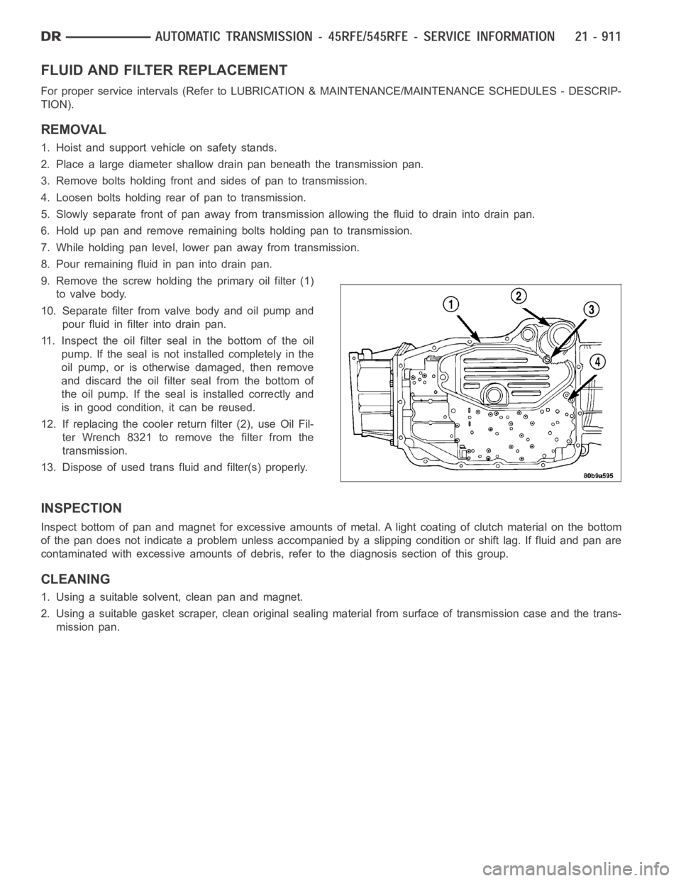
9. Remove the screw holding the primary oil filter (1)
to valve body.
10. Separate filter from valve body and oil pump and
pour fluid in filter into drain pan.
11. Inspect the oil filter seal in the bottom of the oil
pump. If the seal is not installed completely in the
oil pump, or is otherwise damaged, then remove
and discard the oil filter seal from the bottom of
the oil pump. If the seal is installed correctly and
is in good condition, it can be reused.
12. If replacing the cooler return filter (2), use Oil Fil-
ter Wrench 8321 to remove the filter from the
transmission.
13. Dispose of used trans fluid and filter(s) properly.
INSPECTION
Inspect bottom of pan and magnet for excessive amounts of metal. A light coating of clutch material on the bottom
of the pan does not indicate a problem unless accompanied by a slipping condition or shift lag. If fluid and pan are
contaminated with excessive amounts of debris, refer to the diagnosis section of this group.
CLEANING
1. Using a suitable solvent, clean pan and magnet.
2. Using a suitable gasket scraper, clean original sealing material from surface of transmission case and the trans-
mission pan.