2006 DODGE RAM SRT-10 instrument cluster
[x] Cancel search: instrument clusterPage 401 of 5267
U0155-NO CLUSTER BUS MESSAGE
For a complete wiring diagramRefer to Section 8W.
When Monitored:
Ignition key on and battery voltage greater than 10.4 volts.
Set Condition:
No messages received from the MIC (Instrument Cluster) for more than 20 seconds. One Trip Fault. Three
good trips to turn off the MIL.
Possible Causes
BUS CIRCUIT OPEN OR SHORTED
INSTRUMENT CLUSTER
PCM
Refer to 8 - ELECTRICAL/ELECTRONIC CONTROL MODULES - DIAGNOSIS AND TESTING for diagnostic
procedures and for further possible causes.
Always perform the Pre-Diagnostic Troubleshooting procedure before proceeding (Refer to 9 - ENGINE -
DIAGNOSIS AND TESTING).
Diagnostic Test
1.ACTIVE DTC
Ignition on, engine not running.
With the scan tool, erase DTCs.
Cycle the ignition key on and off several times.
With the scan tool, read DTCs.
Does the DTC reset?
Ye s>>
Go To 2
No>>
Refer to the INTERMITTENT CONDITIONSymptom (Diagnostic Procedure).
Perform the POWERTRAIN VERIFICATION TEST. (Refer to 9 - ENGINE - STANDARD PROCEDURE)
2.COMMUNICATE WITH CLUSTER
With the scan tool, attempt to communicate with the Instrument cluster.
Can communication be established with the Instrument Cluster?
Ye s>>
Go To 3
No>>
Refer to 8 - ELECTRICAL/ELECTRONIC CONTROL MODULES - DIAGNOSIS AND TESTING for diag-
nostic procedures and for further possible causes.
Perform the POWERTRAIN VERIFICATION TEST. (Refer to 9 - ENGINE - STANDARD PROCEDURE)
3.INSTRUMENT CLUSTER OPERATION
Start the engine
Allow the engine to idle.
Is the correct engine speed display in the instrument cluster (Tach)?
Ye s>>
Replace and program the Powertrain Control Module per Service Information.
Perform the POWERTRAIN VERIFICATION TEST. (Refer to 9 - ENGINE - STANDARD PROCEDURE)
No>>
Refer to the Instrument Category and perform the appropriate symptom.
Perform the POWERTRAIN VERIFICATION TEST. (Refer to 9 - ENGINE - STANDARD PROCEDURE)
Page 433 of 5267

Possible Causes
NO START PRE-TEST
POWERTRAIN FUSES OPEN
SECONDARY INDICATORS PRESENT
ENGINE MECHANICAL
(K342) ASD RELAY OUTPUT CIRCUITS OPEN
FUEL CONTAMINATION
Diagnostic Test
1.NO START PRE-TEST
NOTE: The following list of items must be checked before continuing with any no start tests.
The battery must be fully charged and in good condition. A low charged battery may produce invalid test results. If
the battery is low, charge the battery and then attempt to start the vehicleby cranking the engine for 15 seconds,
3 consecutive times.
This will allow any DTCs to set that may have been erased due to a dead battery.
Try to communicate with PCM if not able to communicate check fuses.
Make sure the Powers and Ground to the PCM are OK.
Make sure the PCM communicates with the scan tool and that there are no DTCs stored in the PCM memory. If the
PCM reports a No Response condition, refer to section 8 Electrical Electronic Control Module Electrical Diagnostics
for the proper tests.
Read the PCM DTCs with the scan tool. If any DTCs are present, they must be repaired before continuing with any
other No Start diagnostic tests. Refer to the Table of Contents for the related P-code that is reported by the PCM.
Make sure that the Bus is functional. Attempt to communicate with the Instrument Cluster and VTSS, If you are
unable to establish communications refer to 8 Electrical Electronic Control Module Electrical Diagnostics for the
proper Diagnostic procedures.
The Sentry Key Immobilizer System mustbe operating properly. Check for proper communication with the scan tool
and check for DTCs that may be stored in the Sentry Key Immobilizer Module (SKIM). Repair the DTC(s) before
continuing.
If no DTCs are found, using the scan tool, select Clear PCM (BATT Disconnect).
Crank the engine several times. Using the scan tool, read DTCs. If a DTC is present perform the DTC diagnostics
before continuing.
Were any problems found?
Ye s>>
Repair as necessary.
Perform the POWERTRAIN VERIFICATION TEST. (Refer to 9 - ENGINE - STANDARD PROCEDURE)
No>>
Go To 2
2.OPEN FUSE
Check for any open fuses in the IPM or Junction Block that may be related to theNoStartcondition.
Are any of the fuses open?
Ye s>>
Replace the open fuse and check the related circuit(s) for a short to ground.
Perform the POWERTRAIN VERIFICATION TEST. (Refer to 9 - ENGINE - STANDARD PROCEDURE)
No>>
Go To 3
Page 1289 of 5267
When Monitored:
Ignition on and battery voltage above 10.4 volts.
Set Condition:
The fuel level sensor signal voltage goes below 0.4 of a volt for more than 90seconds. One Trip Fault. Three
good trips to turn off the MIL.
Possible Causes
(N4) FUEL LEVEL SIGNAL CIRCUIT SHORTED TO GROUND
(N4) FUEL LEVEL SIGNAL CIRCUIT SHORTED TO THE (K900) SENSOR GROUND CIRCUIT
FUEL LEVEL SENSOR
INSTRUMENT CLUSTER
Always perform the Pre-Diagnostic Troubleshooting procedure before proceeding. (Refer to 9 - ENGINE -
SCHEMATICS AND DIAGRAMS).
Diagnostic Test
1.FUEL LEVEL SENSOR VOLTAGE BELOW 0.4 OF A VOLT
NOTE: Diagnose any Bus Message failures before continuing.
Ignition on, engine not running.
With the scan tool, read the Fuel Level Sensor voltage.
Is the Fuel Level Sensor voltage below 0.4 of a volt?
Ye s>>
Go To 2
No>>
Refer to the INTERMITTENT CONDITION Diagnostic Procedure.
Perform the POWERTRAIN VERIFICATION TEST. (Refer to 9 - ENGINE - STANDARD PROCEDURE)
2.FUEL LEVEL SENSOR
Turn the ignition off.
Disconnect the Fuel Pump Module harness connector.
Ignition on, engine not running.
With the scan tool, read the Fuel Level Sensor voltage.
Did the Fuel Level Sensor voltage change from below 0.4 of a volt to above 4.0volts?
Ye s>>
Replace the Fuel Level Sensor.
Perform the POWERTRAIN VERIFICATION TEST. (Refer to 9 - ENGINE - STANDARD PROCEDURE)
No>>
Go To 3
Page 1456 of 5267
When Monitored:
With the ignition on.
Set Condition:
The PCM has not received an expected Cluster Status Bus message from the instrument cluster within the last
20 seconds.
Possible Causes
(D25) OPEN BETWEEN PCM AND CLUSTER
(D25) SHORTED BETWEEN PCM AND CLUSTER
CLUSTER
PCM
Always perform the Pre-Diagnostic Troubleshooting procedure before proceeding. (Refer to 9 - ENGINE -
DIAGNOSIS AND TESTING)
Diagnostic Test
1.NO CLUSTER BUS MESSAGE
Ignition on, engine not running.
With the scan tool, erase DTCs.
Cycle the ignition key on and off several times.
With the scan tool, read DTCs.
Does the DTC reset?
Ye s>>
Go To 2
No>>
Refer to the INTERMITTENT CONDITION Diagnostic Procedure.
Perform the POWERTRAIN VERIFICATION TEST. (Refer to 9 - ENGINE - STANDARD PROCEDURE)
2.COMMUNICATE WITH CLUSTER
Ignition on, engine not running.
With the scan tool, attempt to communicate with the Instrument cluster.
Can communication be established with the Instrument Cluster?
Ye s>>
Go To 3
No>>
Refer to the Communication Category of the Body Diagnostic Manual and perform the appropriate
symptom related to no communication with cluster.
Perform the POWERTRAIN VERIFICATION TEST. (Refer to 9 - ENGINE - STANDARD PROCEDURE)
3.INSTRUMENT CLUSTER OPERATION
Start the engine
Allow the engine to idle.
Is the correct engine speed display in the instrument cluster (Tach)?
Ye s>>
Replace and program the Powertrain Control Module per Service Information.
Perform the POWERTRAIN VERIFICATION TEST. (Refer to 9 - ENGINE - STANDARD PROCEDURE)
No>>
Refer to the Instrument Category in the Body Diagnostic Manual and performthe appropriate symptom.
Perform the POWERTRAIN VERIFICATION TEST. (Refer to 9 - ENGINE - STANDARD PROCEDURE)
Page 2247 of 5267
SENSOR - FUEL LEVEL SENDING UNIT
DESCRIPTION
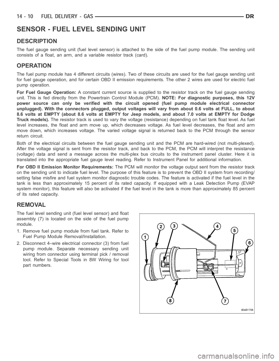
The fuel gauge sending unit (fuel level sensor) is attached to the side of the fuel pump module. The sending unit
consists of a float, an arm, and a variable resistor track (card).
OPERATION
The fuel pump module has 4 different circuits (wires). Two of these circuits are used for the fuel gauge sending unit
for fuel gauge operation, and for certain OBD II emission requirements. The other 2 wires are used for electric fuel
pump operation.
For Fuel Gauge Operation:A constant current source is supplied to the resistor track on the fuel gauge sending
unit. This is fed directly from the Powertrain Control Module (PCM).NOTE: For diagnostic purposes, this 12V
power source can only be verified with the circuit opened (fuel pump moduleelectrical connector
unplugged). With the connectors plugged, output voltages will vary from about 0.6 volts at FULL, to about
8.6 volts at EMPTY (about 8.6 volts at EMPTY for Jeep models, and about 7.0 volts at EMPTY for Dodge
Truck models).The resistor track is used to vary the voltage (resistance) depending on fuel tank float level. As fuel
level increases, the float and arm move up, which decreases voltage. As fuel level decreases, the float and arm
move down, which increases voltage. The varied voltage signal is returnedback to the PCM through the sensor
return circuit.
Both of the electrical circuits between the fuel gauge sending unit and thePCM are hard-wired (not multi-plexed).
After the voltage signal is sent from the resistor track, and back to the PCM, the PCM will interpret the resistance
(voltage) data and send a message across the multi-plex bus circuits to theinstrument panel cluster. Here it is
translated into the appropriate fuel gauge level reading. Refer to Instrument Panel for additional information.
For OBD II Emission Monitor Requirements:The PCM will monitor the voltage output sent from the resistor track
on the sending unit to indicate fuel level. The purpose of this feature is toprevent the OBD II system from recording/
setting false misfire and fuel systemmonitor diagnostic trouble codes. The feature is activated if the fuel level in the
tank is less than approximately 15 percent of its rated capacity. If equipped with a Leak Detection Pump (EVAP
system monitor), this feature will also be activated if the fuel level in the tank is more than approximately 85 percent
of its rated capacity.
REMOVAL
The fuel level sending unit (fuel level sensor) and float
assembly (7) is located on the side of the fuel pump
module.
1. Remove fuel pump module from fuel tank. Refer to
Fuel Pump Module Removal/Installation.
2. Disconnect 4–wire electrical connector (3) from fuel
pump module. Separate necessary sending unit
wiring from connector using terminal pick / removal
tool. Refer to Special Tools in 8W Wiring for tool
part numbers.
Page 2361 of 5267
SENSOR - FUEL LEVEL SENDING UNIT
DESCRIPTION
The fuel gauge sending unit (fuel level sensor) is attached to the side of the fuel pump module. The sending unit
consists of a float, an arm, and a variable resistor track (card). The fuel transfer (lift) pump is also attached to the
fuel pump module.
OPERATION
For Fuel Gauge Operation:A constant input voltage source of about 12 volts (battery voltage) is supplied to the
resistor track on the fuel gauge sending unit. This is fed directly from theEngine Control Module (ECM).NOTE: For
diagnostic purposes, this 12V power source can only be verified with the circuit opened (fuel tank module
electrical connector unplugged). With the connectors plugged, output voltages will vary from about .6 volts
at FULL, to about 7.0 volts at EMPTY.The resistor track is used to vary the voltage (resistance) depending on fuel
tank float level. As fuel level increases, the float and arm move up, which decreases voltage. As fuel level
decreases, the float and arm move down, which increases voltage. The varied voltage signal is returned back to the
ECM through the sensor return circuit.
Both of the electrical circuits between the fuel gauge sending unit and theECM are hard-wired (not multi-plexed).
After the voltage signal is sent from the resistor track, and back to the ECM, the ECM will interpret the resistance
(voltage) data and send a message across the multi-plex bus circuits to theinstrument panel cluster. Here it is
translated into the appropriate fuel gauge level reading. Refer to Instrument Panel for additional information.
REMOVAL
REMOVAL/INSTALLATION
For diesel removal and installation procedures, refer to the gas section of Fuel System/Fuel Delivery. See Fuel
Level Sending Unit/Sensor Removal/Installation.
Page 3963 of 5267
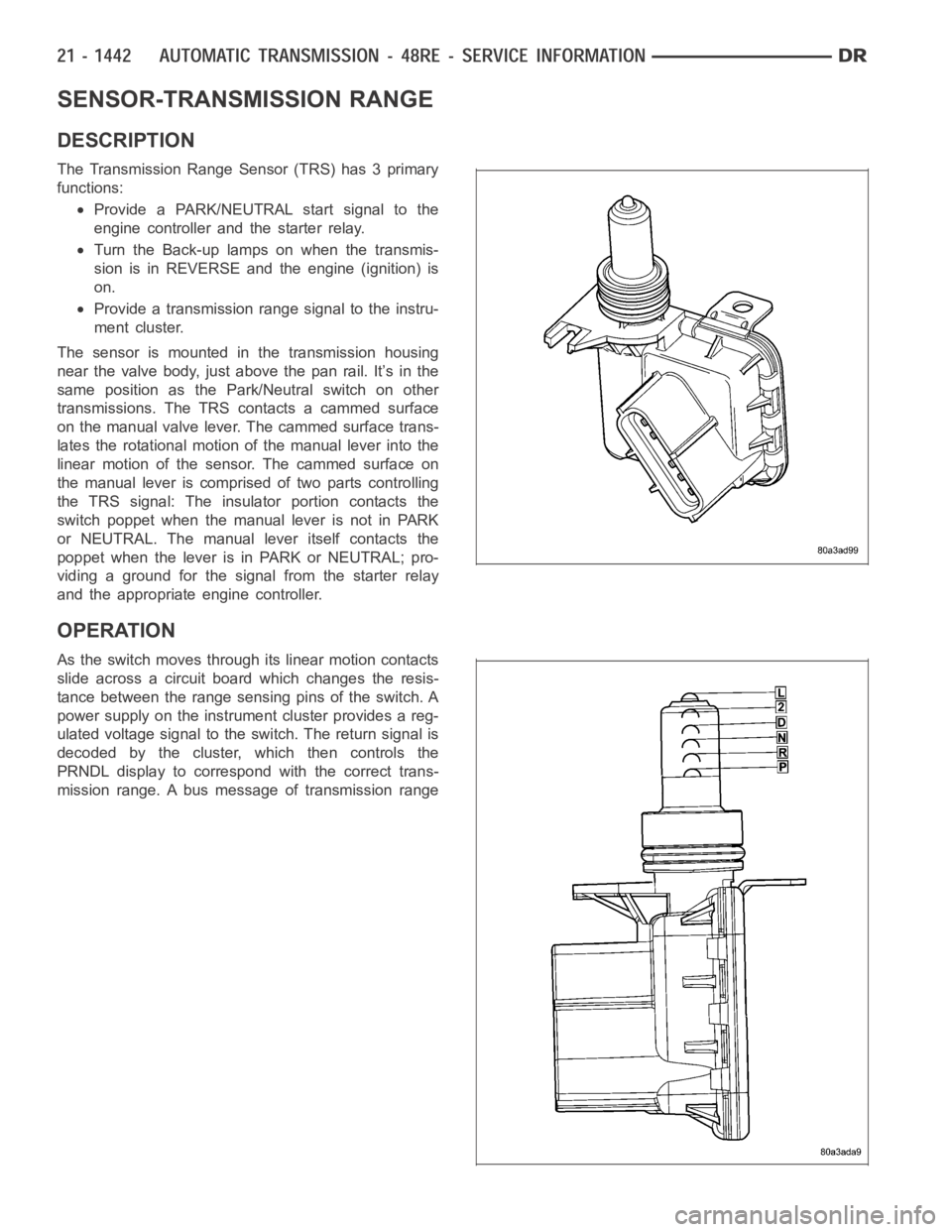
SENSOR-TRANSMISSION RANGE
DESCRIPTION
The Transmission Range Sensor (TRS) has 3 primary
functions:
Provide a PARK/NEUTRAL start signal to the
engine controller and the starter relay.
Turn the Back-up lamps on when the transmis-
sion is in REVERSE and the engine (ignition) is
on.
Provide a transmission range signal to the instru-
ment cluster.
The sensor is mounted in the transmission housing
near the valve body, just above the pan rail. It’s in the
same position as the Park/Neutral switch on other
transmissions. The TRS contacts a cammed surface
on the manual valve lever. The cammed surface trans-
lates the rotational motion of the manual lever into the
linear motion of the sensor. The cammed surface on
the manual lever is comprised of two parts controlling
the TRS signal: The insulator portion contacts the
switch poppet when the manual lever is not in PARK
or NEUTRAL. The manual lever itself contacts the
poppet when the lever is in PARK or NEUTRAL; pro-
viding a ground for the signal from the starter relay
and the appropriate engine controller.
OPERATION
As the switch moves through its linear motion contacts
slide across a circuit board which changes the resis-
tance between the range sensing pins of the switch. A
power supply on the instrument cluster provides a reg-
ulated voltage signal to the switch. The return signal is
decoded by the cluster, which then controls the
PRNDL display to correspond with the correct trans-
mission range. A bus message of transmission range
Page 4023 of 5267
When Monitored:
With the ignition on.
Set Condition:
Transfer Case Range Select Switch voltage less than 0.1568 volts for 5 seconds
Possible Causes
(K77) 5 VOLT SELECTOR SWITCH SUPPLY CIRCUIT OPEN
(K77) 5 VOLT SELECTOR SWITCH SUPPLY CIRCUIT SHORTED TO GROUND
(K977) MODE SELECT CIRCUIT OPEN
(K977) MODE SELECT CIRCUIT SHORT TO GROUND
TRANSFER CASE SELECTOR SWITCH
INSTRUMENT CLUSTER
Diagnostic Test
1.TRANSFER CASE SWITCH VOLTAGE LESS THAN 0.2 VOLTS
Ignition on, engine not running.
With the scan tool under Instrument Cluster, read the Transfer Case Switchvoltage.
Is the voltage less than 0.2 volts?
Ye s>>
Go To 2
No>>
Go To 8
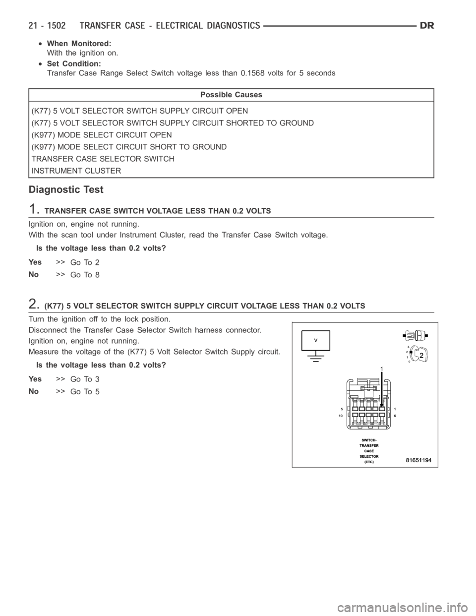
2.(K77) 5 VOLT SELECTOR SWITCH SUPPLY CIRCUIT VOLTAGE LESS THAN 0.2 VOLTS
Turn the ignition off to the lock position.
Disconnect the Transfer Case Selector Switch harness connector.
Ignition on, engine not running.
Measure the voltage of the (K77) 5 Volt Selector Switch Supply circuit.
Is the voltage less than 0.2 volts?
Ye s>>
Go To 3
No>>
Go To 5