2006 DODGE RAM SRT-10 wheel bolts
[x] Cancel search: wheel boltsPage 1538 of 5267
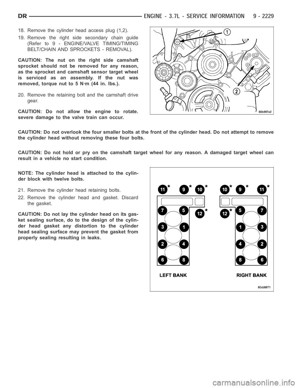
18. Remove the cylinder head access plug (1,2).
19. Remove the right side secondary chain guide
(Refer to 9 - ENGINE/VALVE TIMING/TIMING
BELT/CHAIN AND SPROCKETS - REMOVAL).
CAUTION: The nut on the right side camshaft
sprocket should not be removed for any reason,
as the sprocket and camshaft sensor target wheel
is serviced as an assembly. If the nut was
removed, torque nut to 5 Nꞏm (44 in. lbs.).
20. Remove the retaining bolt and the camshaft drive
gear.
CAUTION: Do not allow the engine to rotate.
severe damage to the valve train can occur.
CAUTION: Do not overlook the four smaller bolts at the front of the cylinderhead.Donotattempttoremove
the cylinder head without removing these four bolts.
CAUTION: Do not hold or pry on the camshaft target wheel for any reason. A damaged target wheel can
result in a vehicle no start condition.
NOTE: The cylinder head is attached to the cylin-
der block with twelve bolts.
21. Remove the cylinder head retaining bolts.
22. Remove the cylinder head and gasket. Discard
the gasket.
CAUTION: Do not lay the cylinder head on its gas-
ket sealing surface, do to the design of the cylin-
der head gasket any distortion to the cylinder
head sealing surface may prevent the gasket from
properly sealing resulting in leaks.
Page 1556 of 5267
REMOVAL
NOTE: To remove the crankshaft from the engine, the engine must be removed from the vehicle.
1. Remove the engine (Refer to 9 - ENGINE - REMOVAL).
2. Remove the engine oil pump (Refer to 9- ENGINE/LUBRICATION/OIL PUMP - REMOVAL).
CAUTION: DO NOT pry on the oil pan gasket when removing the oil pan, The oil pan gasket is mounted to
the cylinder block in three locations and will remain attached to block when removing oil pan. Gasket can
not be removed with oil pan.
3. Remove the bedplate mounting bolts. Note the location of the two stud bolts for installation.
4. Remove the connecting rods from the crankshaft.
CAUTION: The bedplate to cylinder block mating surface is a critical sealing surface. Do not pry on or dam-
age this surface in anyway.
NOTE: The bedplate contains the lower main bearing halves. Use care when handling bedplate as not to
drop or damage bearing halves. Installing main bearing halves in the wrongposition will cause severe dam-
age to the crankshaft.
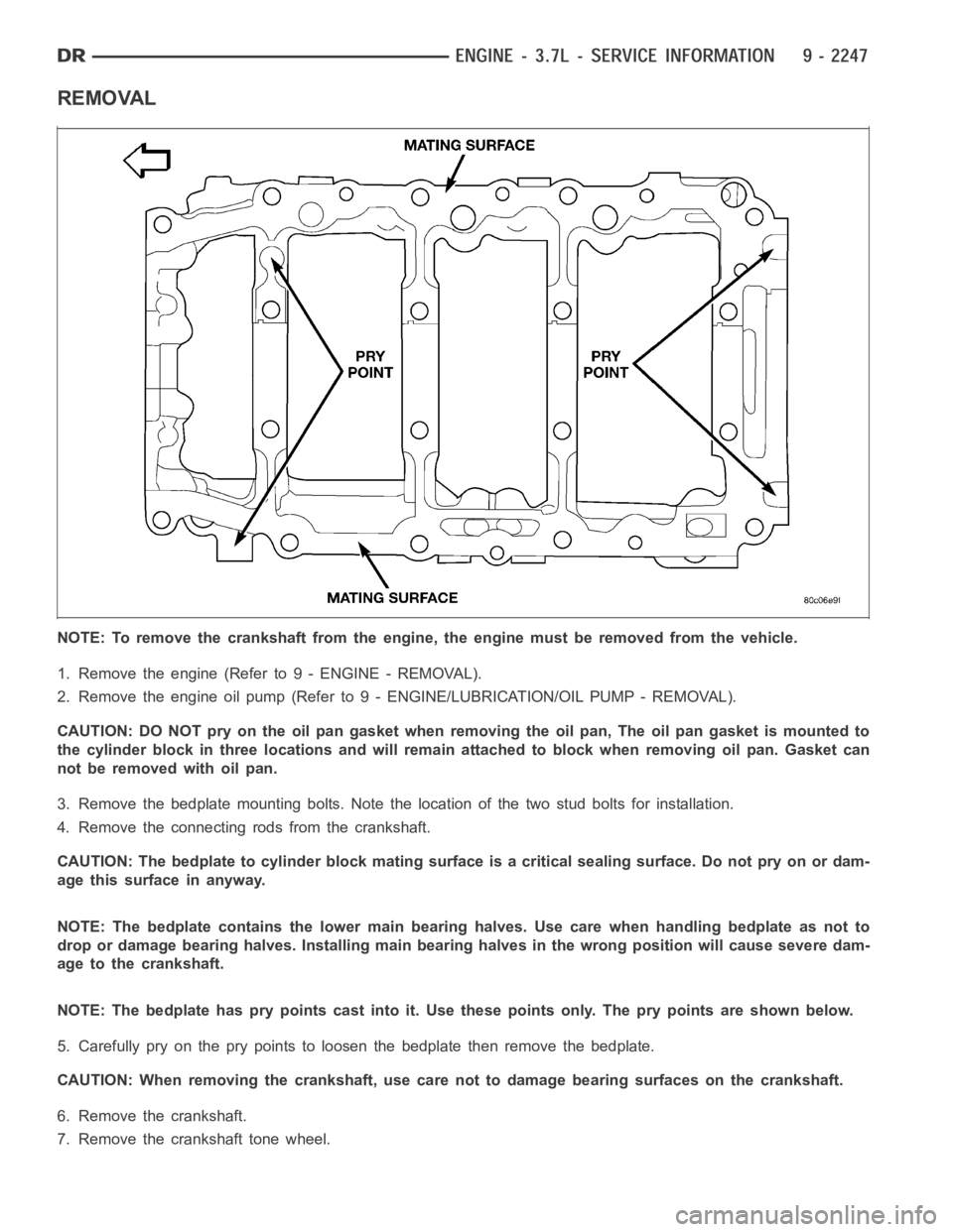
NOTE: The bedplate has pry points cast into it. Use these points only. The pry points are shown below.
5. Carefully pry on the pry points to loosen the bedplate then remove the bedplate.
CAUTION: When removing the crankshaft, use care not to damage bearing surfaces on the crankshaft.
6. Remove the crankshaft.
7. Remove the crankshaft tone wheel.
Page 1618 of 5267
CAUTION: Care should be taken not to damage
camshaft target wheel. Do not hold target wheel
while loosening or tightening camshaft sprocket.
Do not place the target wheel near a magnetic
source of any kind. A damaged or magnetized tar-
get wheel could cause a vehicle no start condition.
CAUTION: Do not forcefully rotate the camshafts
or crankshaft independently of each other. Damag-
ing intake valve to piston contact will occur.
Ensure negative battery cable is disconnected to
guard against accidental starter engagement.
13. Remove left and right camshaft sprocket bolts.
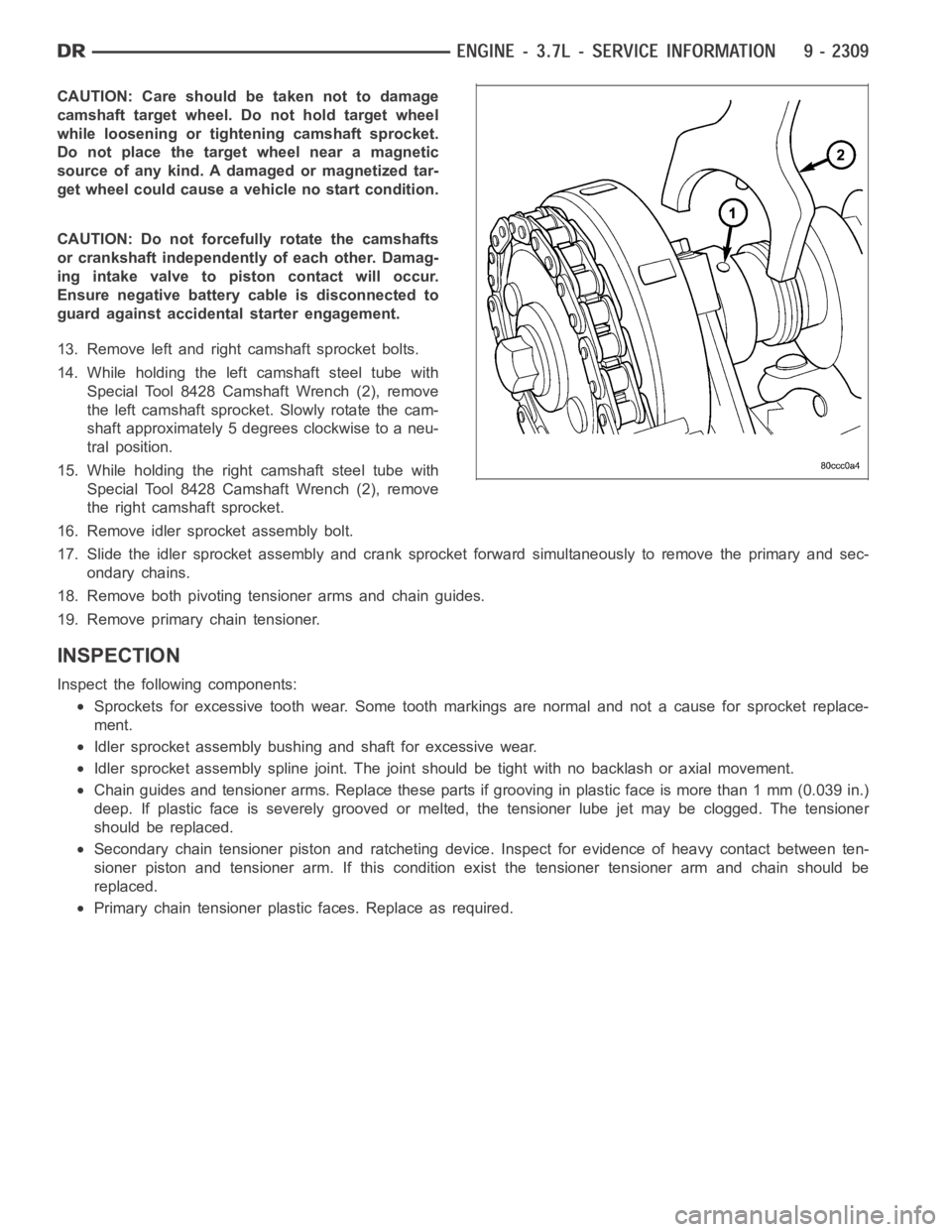
14. While holding the left camshaft steel tube with
Special Tool 8428 Camshaft Wrench (2), remove
the left camshaft sprocket. Slowly rotate the cam-
shaft approximately 5 degrees clockwise to a neu-
tral position.
15. While holding the right camshaft steel tube with
Special Tool 8428 Camshaft Wrench (2), remove
the right camshaft sprocket.
16. Remove idler sprocket assembly bolt.
17. Slide the idler sprocket assembly and crank sprocket forward simultaneously to remove the primary and sec-
ondary chains.
18. Remove both pivoting tensioner arms and chain guides.
19. Remove primary chain tensioner.
INSPECTION
Inspect the following components:
Sprockets for excessive tooth wear. Some tooth markings are normal and nota cause for sprocket replace-
ment.
Idler sprocket assembly bushing and shaft for excessive wear.
Idler sprocket assembly spline joint. The joint should be tight with no backlash or axial movement.
Chain guides and tensioner arms. Replace these parts if grooving in plasticfaceismorethan1mm(0.039in.)
deep. If plastic face is severely grooved or melted, the tensioner lube jetmay be clogged. The tensioner
should be replaced.
Secondary chain tensioner piston and ratcheting device. Inspect for evidence of heavy contact between ten-
sioner piston and tensioner arm. If this condition exist the tensioner tensioner arm and chain should be
replaced.
Primary chain tensioner plastic faces. Replace as required.
Page 1659 of 5267
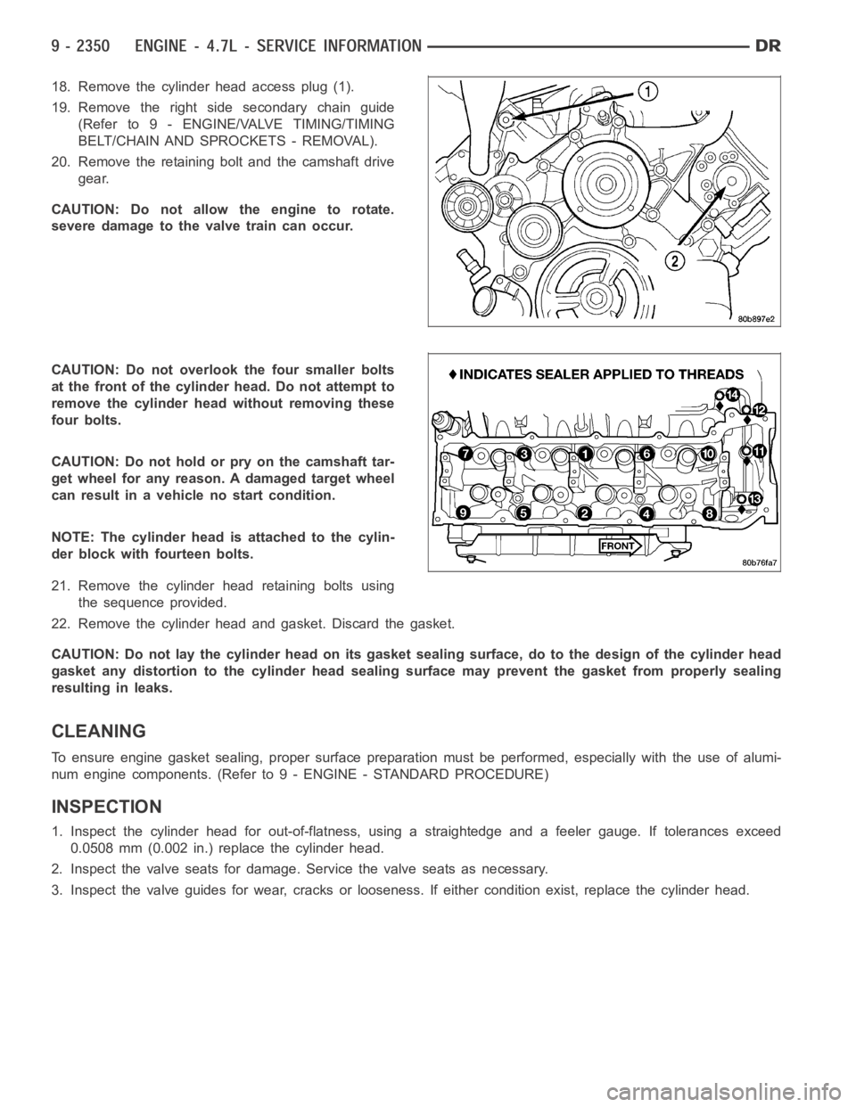
18. Remove the cylinder head access plug (1).
19. Remove the right side secondary chain guide
(Refer to 9 - ENGINE/VALVE TIMING/TIMING
BELT/CHAIN AND SPROCKETS - REMOVAL).
20. Remove the retaining bolt and the camshaft drive
gear.
CAUTION: Do not allow the engine to rotate.
severe damage to the valve train can occur.
CAUTION: Do not overlook the four smaller bolts
at the front of the cylinder head. Do not attempt to
remove the cylinder head without removing these
four bolts.
CAUTION: Do not hold or pry on the camshaft tar-
get wheel for any reason. A damaged target wheel
can result in a vehicle no start condition.
NOTE: The cylinder head is attached to the cylin-
der block with fourteen bolts.
21. Remove the cylinder head retaining bolts using
the sequence provided.
22. Remove the cylinder head and gasket. Discard the gasket.
CAUTION: Do not lay the cylinder head on its gasket sealing surface, do to the design of the cylinder head
gasket any distortion to the cylinder head sealing surface may prevent thegasket from properly sealing
resulting in leaks.
CLEANING
To ensure engine gasket sealing, proper surface preparation must be performed, especially with the use of alumi-
num engine components. (Refer to 9 - ENGINE - STANDARD PROCEDURE)
INSPECTION
1. Inspect the cylinder head for out-of-flatness, using a straightedge and a feeler gauge. If tolerances exceed
0.0508 mm (0.002 in.) replace the cylinder head.
2. Inspect the valve seats for damage. Service the valve seats as necessary.
3. Inspect the valve guides for wear, cracks or looseness. If either condition exist, replace the cylinder head.
Page 1694 of 5267
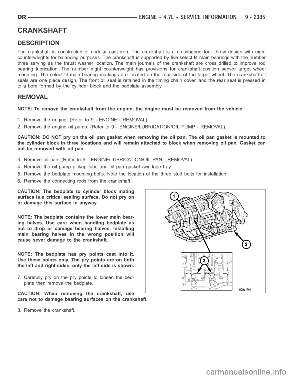
CRANKSHAFT
DESCRIPTION
The crankshaft is constructed of nodular cast iron. The crankshaft is a crosshaped four throw design with eight
counterweights for balancing purposes. The crankshaft is supported by five select fit main bearings with the number
three serving as the thrust washer location. The main journals of the crankshaft are cross drilled to improve rod
bearing lubrication. The number eight counterweight has provisions for crankshaft position sensor target wheel
mounting. The select fit main bearing markings are located on the rear sideof the target wheel. The crankshaft oil
seals are one piece design. The front oil seal is retained in the timing chain cover, and the rear seal is pressed in
to a bore formed by the cylinder block and the bedplate assembly.
REMOVAL
NOTE: To remove the crankshaft from the engine, the engine must be removed from the vehicle.
1. Remove the engine. (Refer to 9 - ENGINE - REMOVAL).
2. Remove the engine oil pump. (Refer to 9 - ENGINE/LUBRICATION/OIL PUMP - REMOVAL).
CAUTION: DO NOT pry on the oil pan gasket when removing the oil pan, The oil pan gasket is mounted to
the cylinder block in three locations and will remain attached to block when removing oil pan. Gasket can
not be removed with oil pan.
3. Remove oil pan. (Refer to 9 - ENGINE/LUBRICATION/OIL PAN - REMOVAL).
4. Remove the oil pump pickup tube and oil pan gasket /windage tray.
5. Remove the bedplate mounting bolts. Note the location of the three stud bolts for installation.
6. Remove the connecting rods from the crankshaft.
CAUTION: The bedplate to cylinder block mating
surface is a critical sealing surface. Do not pry on
or damage this surface in anyway.
NOTE: The bedplate contains the lower main bear-
ing halves. Use care when handling bedplate as
not to drop or damage bearing halves. Installing
main bearing halves in the wrong position will
cause sever damage to the crankshaft.
NOTE: The bedplate has pry points cast into it.
Use these points only. The pry points are on both
the left and right sides, only the left side is shown.
7. Carefully pry on the pry points to loosen the bed-
plate then remove the bedplate.
CAUTION: When removing the crankshaft, use
care not to damage bearing surfaces on the crankshaft.
8. Remove the crankshaft.
Page 1749 of 5267
CAUTION: Care should be taken not to damage
camshaft target wheel. Do not hold target wheel
while loosening or tightening camshaft sprocket.
Do not place the target wheel near a magnetic
source of any kind. A damaged or magnetized tar-
get wheel could cause a vehicle no start condition.
CAUTION: Do not forcefully rotate the camshafts
or crankshaft independently of each other. Damag-
ing intake valve to piston contact will occur.
Ensure negative battery cable is disconnected to
guard against accidental starter engagement.
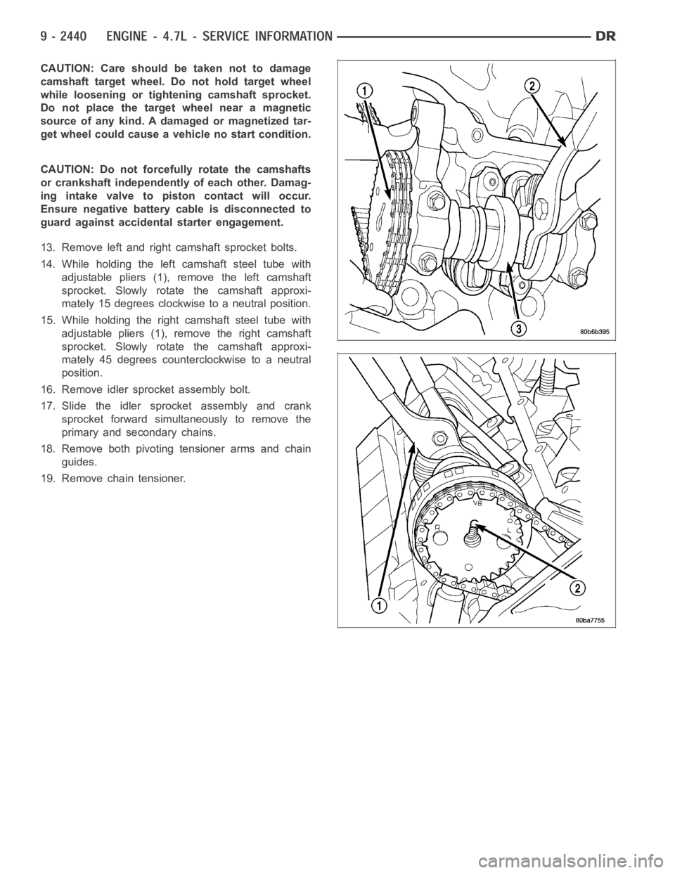
13. Remove left and right camshaft sprocket bolts.
14. While holding the left camshaft steel tube with
adjustable pliers (1), remove the left camshaft
sprocket. Slowly rotate the camshaft approxi-
mately 15 degrees clockwise to a neutral position.
15. While holding the right camshaft steel tube with
adjustable pliers (1), remove the right camshaft
sprocket. Slowly rotate the camshaft approxi-
mately 45 degrees counterclockwise to a neutral
position.
16. Remove idler sprocket assembly bolt.
17. Slide the idler sprocket assembly and crank
sprocket forward simultaneously to remove the
primary and secondary chains.
18. Remove both pivoting tensioner arms and chain
guides.
19. Remove chain tensioner.
Page 1764 of 5267
CONDITION POSSIBLE CAUSES CORRECTION
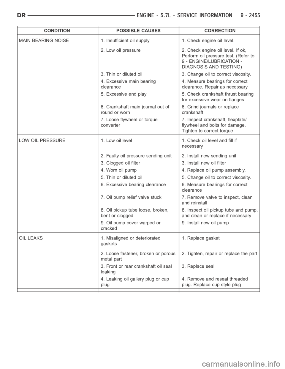
MAIN BEARING NOISE 1. Insufficient oil supply 1. Check engine oil level.
2. Low oil pressure 2. Check engine oil level. If ok,
Perform oil pressure test. (Refer to
9 - ENGINE/LUBRICATION -
DIAGNOSIS AND TESTING)
3. Thin or diluted oil 3. Change oil to correct viscosity.
4. Excessive main bearing
clearance4. Measure bearings for correct
clearance. Repair as necessary
5. Excessive end play 5. Check crankshaft thrust bearing
for excessive wear on flanges
6. Crankshaft main journal out of
round or worn6. Grind journals or replace
crankshaft
7. Loose flywheel or torque
converter7. Inspect crankshaft, flexplate/
flywheel and bolts for damage.
Tighten to correct torque
LOW OIL PRESSURE 1. Low oil level 1. Check oil level and fill if
necessary
2. Faulty oil pressure sending unit 2. Install new sending unit
3. Clogged oil filter 3. Install new oil filter
4. Worn oil pump 4. Replace oil pump assembly.
5. Thin or diluted oil 5. Change oil to correct viscosity.
6. Excessive bearing clearance 6. Measure bearings for correct
clearance
7. Oil pump relief valve stuck 7. Remove valve to inspect, clean
and reinstall
8. Oil pickup tube loose, broken,
bent or clogged8. Inspect oil pickup tube and pump,
and clean or replace if necessary
9. Oil pump cover warped or
cracked9. Install new oil pump
OIL LEAKS 1. Misaligned or deteriorated
gaskets1. Replace gasket
2. Loose fastener, broken or porous
metal part2. Tighten, repair or replace the part
3. Front or rear crankshaft oil seal
leaking3. Replace seal
4. Leaking oil gallery plug or cup
plug4. Remove and reseal threaded
plug. Replace cup style plug
Page 1781 of 5267
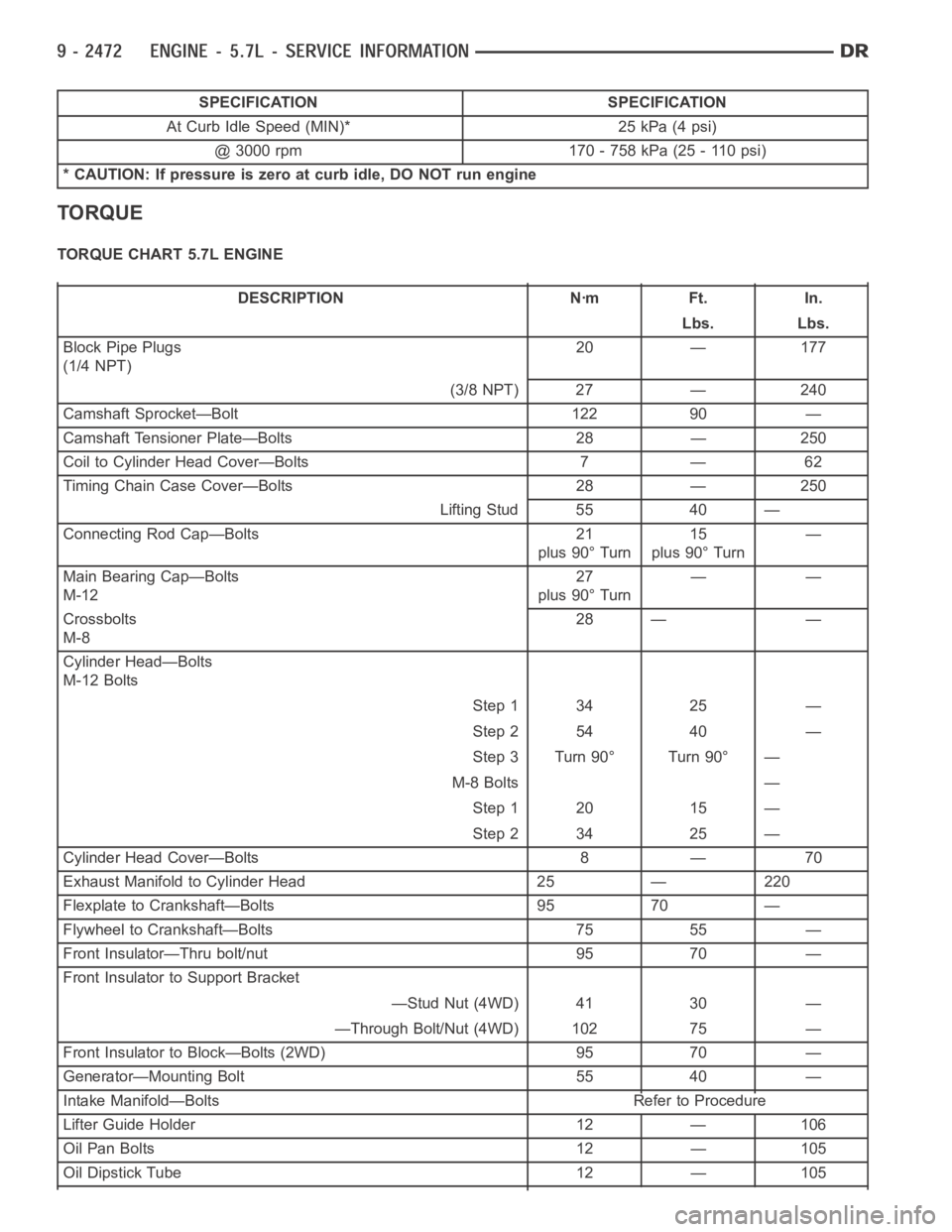
SPECIFICATION SPECIFICATION
At Curb Idle Speed (MIN)* 25 kPa (4 psi)
@ 3000 rpm 170 - 758 kPa (25 - 110 psi)
* CAUTION: If pressure is zero at curb idle, DO NOT run engine
TORQUE
TORQUE CHART 5.7L ENGINE
DESCRIPTION Nꞏm Ft. In.
Lbs. Lbs.
Block Pipe Plugs
(1/4 NPT)20 — 177
(3/8 NPT) 27 — 240
Camshaft Sprocket—Bolt 122 90 —
Camshaft Tensioner Plate—Bolts 28 — 250
Coil to Cylinder Head Cover—Bolts 7 — 62
Timing Chain Case Cover—Bolts 28 — 250
Lifting Stud 55 40 —
Connecting Rod Cap—Bolts 21
plus 90° Turn15
plus 90° Turn—
Main Bearing Cap—Bolts
M-1227
plus 90° Turn——
Crossbolts
M-828 — —
Cylinder Head—Bolts
M-12 Bolts
Step 1 34 25 —
Step 2 54 40 —
Step 3 Turn 90° Turn 90° —
M-8 Bolts —
Step 1 20 15 —
Step 2 34 25 —
Cylinder Head Cover—Bolts 8 — 70
Exhaust Manifold to Cylinder Head 25 — 220
Flexplate to Crankshaft—Bolts 95 70 —
Flywheel to Crankshaft—Bolts 75 55 —
Front Insulator—Thru bolt/nut 95 70 —
Front Insulator to Support Bracket
—Stud Nut (4WD) 41 30 —
—Through Bolt/Nut (4WD) 102 75 —
Front Insulator to Block—Bolts (2WD) 95 70 —
Generator—Mounting Bolt 55 40 —
Intake Manifold—Bolts Refer to Procedure
Lifter Guide Holder 12 — 106
Oil Pan Bolts 12 — 105
Oil Dipstick Tube 12 — 105