2006 DODGE RAM SRT-10 wheel alignment
[x] Cancel search: wheel alignmentPage 468 of 5267

When Monitored:
While Engine is running.
Set Condition:
When the engine speed detected by the Engine Position Sensor (cam) and the Engine Speed Sensor (crank)
differ by a specified RPM amount.
Possible Causes
DAMAGE TO THE ESS OR EPS
MECHANICAL MISALIGNMENT OF THE ESS OR EPS
MECHANICAL MISALIGNMENT OF THE CAMSHAFT AND CRANKSHAFT GEARS
INTERMITTENT CONDITION
Diagnostic Test
1.DAMAGE TO THE ESS OR EPS
Visually inspect the condition of the tone wheel, ESS, and EPS for damage.
Are any of the components damaged?
Ye s>>
Repair or replace any damaged component.
Perform POWERTRAIN VERIFICATION TEST VER - 1 (DIESEL). (Refer to 9 - ENGINE- DIAGNOSIS
AND TESTING)
No>>
Go To 2
2.MECHANICAL MISALIGNMENT OF THE ESS OR EPS
Verify the speed indicator ring is properly positioned relative to the locating pin in the front face of the crankshaft.
Is the speed indicator ring properly installed?
Ye s>>
Go To 3
No>>
Repair the speed ring indicator ring installation.
Perform POWERTRAIN VERIFICATION TEST VER - 1 (DIESEL). (Refer to 9 - ENGINE- DIAGNOSIS
AND TESTING)
3.MECHANICAL MISALIGNMENT OF THE CAMSHAFT AND CRANKSHAFT GEARS
Check the mechanical alignment of the camshaft gear to the crankshaft gear. Refer to service manual for assis-
tance.
Are the gear teeth in proper alignment?
Ye s>>
Refer to the INTERMITTENT CONDITION Symptom (Diagnostic Procedure). (Refer to 9 - ENGINE -
DIAGNOSIS AND TESTING)
No>>
Repair the gear alignment.
Perform POWERTRAIN VERIFICATION TEST VER - 1 (DIESEL). (Refer to 9 - ENGINE- DIAGNOSIS
AND TESTING)
Page 1607 of 5267
loads. Each tensioner also has a mechanical ratchet system that limits chain slack if the tensioner piston bleeds
down after engine shut down. The tensioner arms and guides also utilize nylon wear faces for low friction and long
wear. The secondary timing chains receive lubrication from a small orifice in the tensioners. This orifice is protected
from clogging by a fine mesh screen which is located on the back of the hydraulic tensioners.
STANDARD PROCEDURE
MEASURING TIMING CHAIN WEAR
NOTE: This procedure must be performed with the
timing chain cover removed.
1. Remove the timing chain cover (Refer to 9 -
ENGINE/VALVE TIMING/TIMING BELT/CHAIN
AND SPROCKETS - REMOVAL).
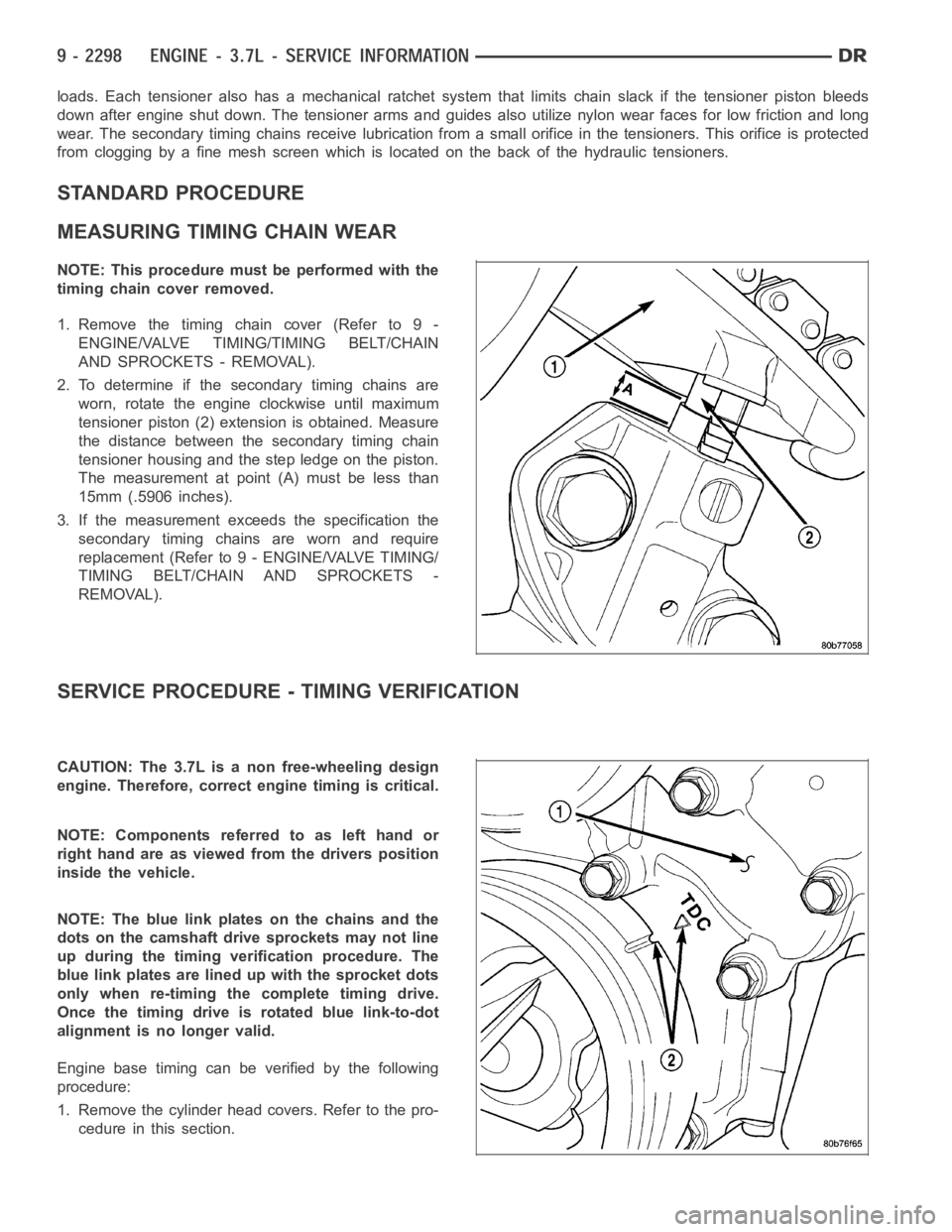
2. To determine if the secondary timing chains are
worn, rotate the engine clockwise until maximum
tensioner piston (2) extension is obtained. Measure
the distance between the secondary timing chain
tensioner housing and the step ledge on the piston.
The measurement at point (A) must be less than
15mm (.5906 inches).
3. If the measurement exceeds the specification the
secondary timing chains are worn and require
replacement (Refer to 9 - ENGINE/VALVE TIMING/
TIMING BELT/CHAIN AND SPROCKETS -
REMOVAL).
SERVICE PROCEDURE - TIMING VERIFICATION
CAUTION: The 3.7L is a non free-wheeling design
engine. Therefore, correct engine timing is critical.
NOTE:Componentsreferredtoaslefthandor
right hand are as viewed from the drivers position
inside the vehicle.
NOTE: The blue link plates on the chains and the
dots on the camshaft drive sprockets may not line
up during the timing verification procedure. The
blue link plates are lined up with the sprocket dots
only when re-timing the complete timing drive.
Once the timing drive is rotated blue link-to-dot
alignment is no longer valid.
Engine base timing can be verified by the following
procedure:
1. Remove the cylinder head covers. Refer to the pro-
cedure in this section.
Page 1740 of 5267
STANDARD PROCEDURE
STANDARD PROCEDURE - MEASURING TIMING CHAIN WEAR
NOTE: This procedure must be performed with the
timing chain cover removed.
1.Removethetimingchaincover.(Referto9-
ENGINE/VALVE TIMING/TIMING BELT / CHAIN
COVER(S) - REMOVAL).
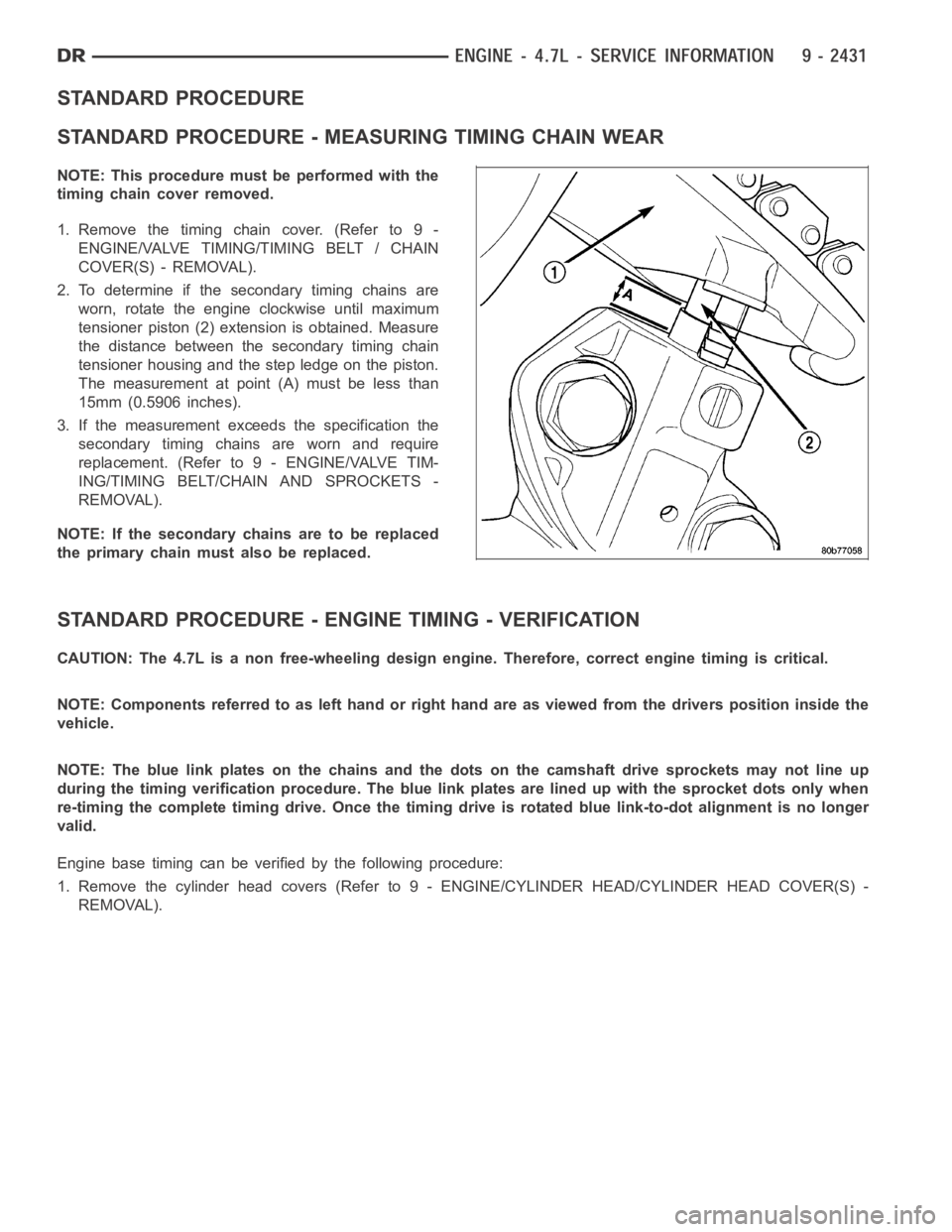
2. To determine if the secondary timing chains are
worn, rotate the engine clockwise until maximum
tensioner piston (2) extension is obtained. Measure
the distance between the secondary timing chain
tensioner housing and the step ledge on the piston.
The measurement at point (A) must be less than
15mm (0.5906 inches).
3. If the measurement exceeds the specification the
secondary timing chains are worn and require
replacement. (Refer to 9 - ENGINE/VALVE TIM-
ING/TIMING BELT/CHAIN AND SPROCKETS -
REMOVAL).
NOTE: If the secondary chains are to be replaced
the primary chain must also be replaced.
STANDARD PROCEDURE - ENGINE TIMING - VERIFICATION
CAUTION: The 4.7L is a non free-wheeling design engine. Therefore, correct engine timing is critical.
NOTE: Components referred to as left hand or right hand are as viewed from thedriverspositioninsidethe
vehicle.
NOTE: The blue link plates on the chains and the dots on the camshaft drive sprockets may not line up
during the timing verification procedure. The blue link plates are lined up with the sprocket dots only when
re-timing the complete timing drive.Once the timing drive is rotated bluelink-to-dot alignment is no longer
valid.
Engine base timing can be verified by the following procedure:
1. Remove the cylinder head covers (Refer to 9 - ENGINE/CYLINDER HEAD/CYLINDERHEADCOVER(S)-
REMOVAL).
Page 1908 of 5267
CONDITION POSSIBLE CAUSES CORRECTION
3. Improperly operating vibration
damper3. Inspect/replace vibration damper.
4. Improperly operating electronically
controlled viscous fan drive.4. Inspect/replace fan drive.
5. Worn or damaged generator
bearing.5. Check/replace generator.
6. Flywheel housing misaligned. 6. Check/correct flywheel alignment.
7. Loose or broken power
component.7. Inspect the crankshaft and rods for
damage that causes an unbalance
condition. Repair/replace as required.
8. Worn or unbalanced driveline
components.8. Check/repair driveline components.
EXCESSIVE ENGINE
NOISES1. Drive belt squeal, insufficient
tension or abnormally high loading.1. Check the automatic tensioner and
inspect the drive belt. Make sure water
pump, tensioner pulley, fan hub, generator
and power steering pump turn freely.
2. Intake air or exhaust leaks. 2. Refer to Excessive Exhaust Smoke
(Refer to 9 - ENGINE - DIAGNOSIS AND
TESTING).
3. Excessive valve lash. 3. Adjust valves. Make sure the push rods
are not bent and rocker arms, adjusting
screws, crossheads, are not severely worn.
Replace bent or severely worn components.
4. Turbocharger noise. 4. Check turbocharger impeller and turbine
wheel for housing contact. Repair/replace
as required.
5. Gear train noise. 5. Visually inspect and measure gear
backlash. Replace gears as required.
6. Power function knock. 6. Check/replace rod and main bearings.
DIAGNOSIS AND TESTING -SMOKE DIAGNOSIS CHARTS
The following charts include possible causes and corrections forexcess or abnormalexhaust smoke. Small
amounts of exhaust smoke (at certain times) are to be considered normal fora diesel powered engine.
EXCESSIVE BLACK SMOKE
POSSIBLE CAUSE CORRECTION
Air filter dirty or plugged. Check Filter Minder
at air filter (Refer to 9 - ENGINE/
AIR INTAKE SYSTEM/AIR CLEANER ELEMENT -
REMOVAL).
Air intake system restricted. Check entire air intake system including all hoses and
tubes for restrictions, collapsed parts or damage.
Repair/replace as necessary.
Air Leak in Intake System. Check entire air intake system (Refer to 11 - EXHAUST
SYSTEM/TURBOCHARGER SYSTEM/CHARGE AIR
COOLER AND PLUMBING - DIAGNOSIS AND
TESTING) including all hoses and tubes for cracks,
loose clamps and/or holes in rubber ducts. Also check
intake manifold for loose mounting hardware.
Diagnostic Trouble Codes (DTC’s) active or multiple,
intermittent DTC’s.Refer to Powertrain Diagnostic Procedures Information.
Page 1979 of 5267
SEAL - CRANKSHAFT OIL - REAR
REMOVAL
1. Disconnect the battery negative cables.
2. Remove the transmission and transfer case (if
equipped).
3. Remove the clutch cover and disc (if manual trans-
mission equipped) (Refer to 6 - CLUTCH/CLUTCH
DISC - REMOVAL).
4. Remove the flywheel or converter drive plate.
5. Remove the flywheel adapter plate.
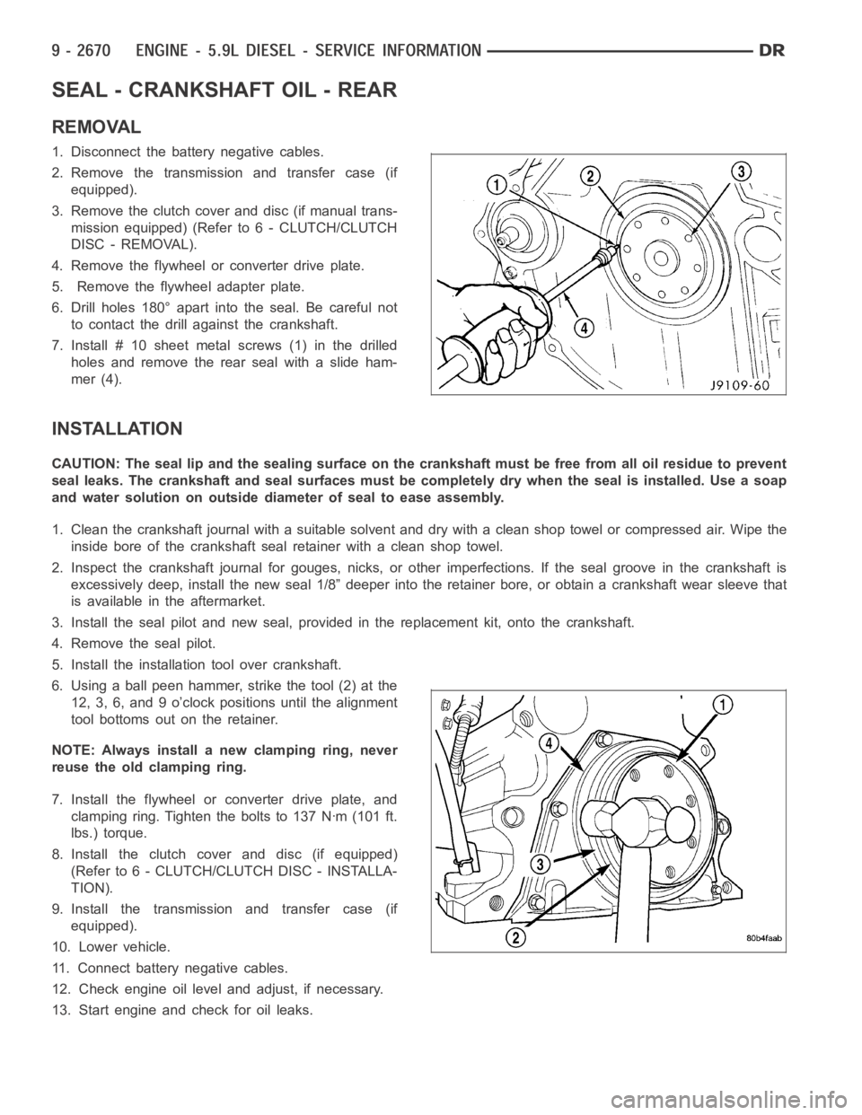
6. Drill holes 180° apart into the seal. Be careful not
to contact the drill against the crankshaft.
7. Install # 10 sheet metalscrews (1) in the drilled
holes and remove the rear seal with a slide ham-
mer (4).
INSTALLATION
CAUTION: The seal lip and the sealing surface on the crankshaft must be freefrom all oil residue to prevent
seal leaks. The crankshaft and seal surfaces must be completely dry when the seal is installed. Use a soap
and water solution on outside diameter of seal to ease assembly.
1. Clean the crankshaft journal with a suitable solvent and dry with a cleanshop towel or compressed air. Wipe the
inside bore of the crankshaft seal retainer with a clean shop towel.
2. Inspect the crankshaft journal forgouges, nicks, or other imperfections. If the seal groove in the crankshaft is
excessively deep, install the new seal 1/8” deeper into the retainer bore,or obtain a crankshaft wear sleeve that
is available in the aftermarket.
3. Install the seal pilot and new seal, provided in the replacement kit, onto the crankshaft.
4. Remove the seal pilot.
5. Install the installation tool over crankshaft.
6. Using a ball peen hammer, strike the tool (2) at the
12, 3, 6, and 9 o’clock positions until the alignment
tool bottoms out on the retainer.
NOTE: Always install a new clamping ring, never
reuse the old clamping ring.
7. Install the flywheel or converter drive plate, and
clamping ring. Tighten the bolts to 137 Nꞏm (101 ft.
lbs.) torque.
8. Install the clutch cover and disc (if equipped)
(Refer to 6 - CLUTCH/CLUTCH DISC - INSTALLA-
TION).
9. Install the transmission and transfer case (if
equipped).
10. Lower vehicle.
11. Connect battery negative cables.
12. Check engine oil level and adjust, if necessary.
13. Start engine and check for oil leaks.
Page 1980 of 5267
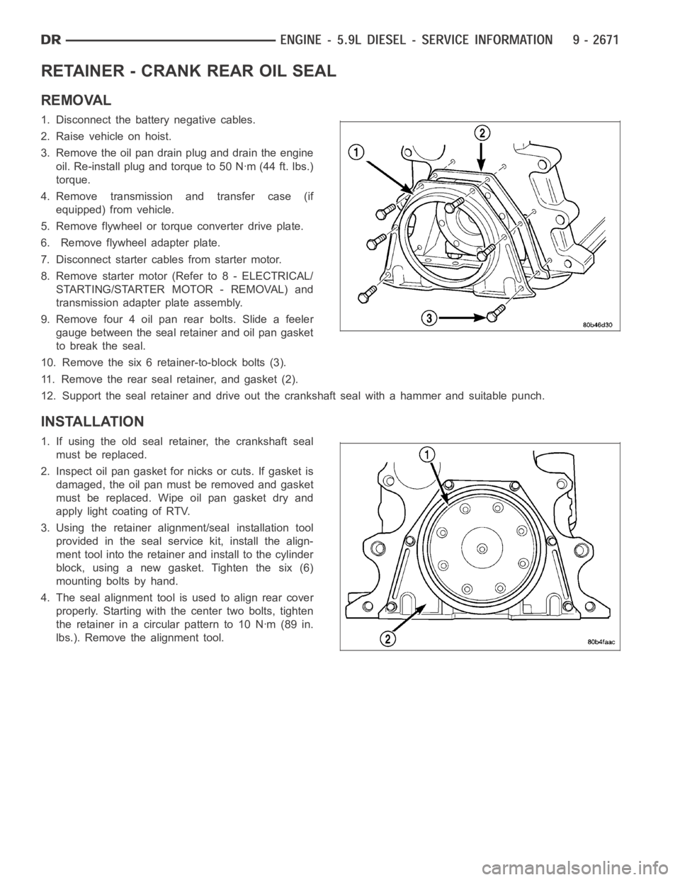
RETAINER - CRANK REAR OIL SEAL
REMOVAL
1. Disconnect the battery negative cables.
2. Raise vehicle on hoist.
3. Remove the oil pan drain plug and drain the engine
oil. Re-install plug and torque to 50 Nꞏm (44 ft. lbs.)
torque.
4. Remove transmission and transfer case (if
equipped) from vehicle.
5. Remove flywheel or torque converter drive plate.
6. Remove flywheel adapter plate.
7. Disconnect starter cables from starter motor.
8. Remove starter motor (Refer to 8 - ELECTRICAL/
STARTING/STARTER MOTOR - REMOVAL) and
transmission adapter plate assembly.
9. Remove four 4 oil pan rear bolts. Slide a feeler
gauge between the seal retainer and oil pan gasket
to break the seal.
10. Remove the six 6 retainer-to-block bolts (3).
11. Remove the rear seal retainer, and gasket (2).
12. Support the seal retainer and drive out the crankshaft seal with a hammer and suitable punch.
INSTALLATION
1. If using the old seal retainer, the crankshaft seal
must be replaced.
2. Inspect oil pan gasket for nicks or cuts. If gasket is
damaged, the oil pan must be removed and gasket
must be replaced. Wipe oil pan gasket dry and
apply light coating of RTV.
3. Using the retainer alignment/seal installation tool
provided in the seal service kit, install the align-
ment tool into the retainer and install to the cylinder
block, using a new gasket. Tighten the six (6)
mounting bolts by hand.
4. The seal alignment tool is used to align rear cover
properly. Starting with the center two bolts, tighten
the retainer in a circular pattern to 10 Nꞏm (89 in.
lbs.). Remove the alignment tool.
Page 1981 of 5267
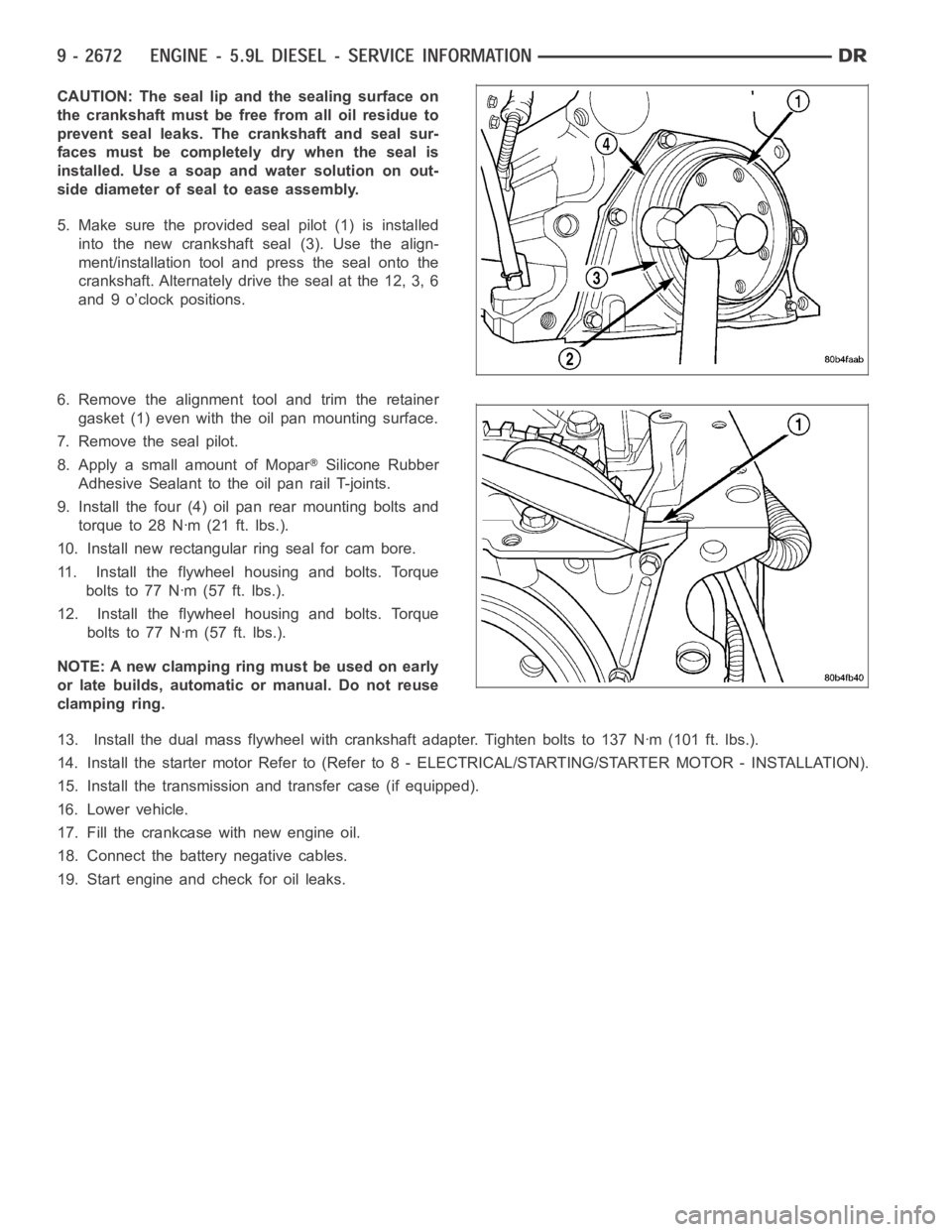
CAUTION: The seal lip and the sealing surface on
the crankshaft must be free from all oil residue to
prevent seal leaks. The crankshaft and seal sur-
faces must be completely dry when the seal is
installed. Use a soap and water solution on out-
side diameter of seal to ease assembly.
5. Make sure the provided seal pilot (1) is installed
into the new crankshaft seal (3). Use the align-
ment/installation tool and press the seal onto the
crankshaft. Alternately drive the seal at the 12, 3, 6
and 9 o’clock positions.
6. Remove the alignment tool and trim the retainer
gasket (1) even with the oil pan mounting surface.
7. Remove the seal pilot.
8. Apply a small amount of Mopar
Silicone Rubber
Adhesive Sealant to the oil pan rail T-joints.
9. Install the four (4) oil pan rear mounting bolts and
torque to 28 Nꞏm (21 ft. lbs.).
10. Install new rectangular ring seal for cam bore.
11. Install the flywheel housing and bolts. Torque
boltsto77Nꞏm(57ft.lbs.).
12. Install the flywheel housing and bolts. Torque
boltsto77Nꞏm(57ft.lbs.).
NOTE: A new clamping ring must be used on early
or late builds, automatic or manual. Do not reuse
clamping ring.
13. Install the dual mass flywheel with crankshaft adapter. Tighten boltsto 137 Nꞏm (101 ft. lbs.).
14. Install the starter motor Refer to (Refer to 8 - ELECTRICAL/STARTING/STA R T E R M O TO R - I N S TA L L AT I O N ) .
15. Install the transmission and transfer case (if equipped).
16. Lower vehicle.
17. Fill the crankcase with new engine oil.
18. Connect the battery negative cables.
19. Start engine and check for oil leaks.
Page 2177 of 5267
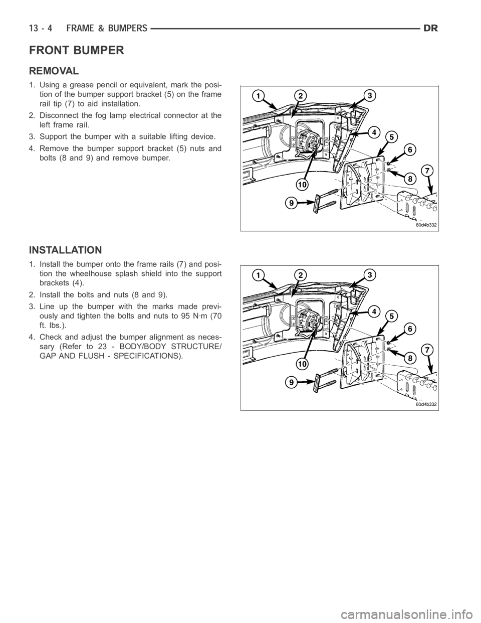
FRONT BUMPER
REMOVAL
1. Using a grease pencil or equivalent, mark the posi-
tion of the bumper support bracket (5) on the frame
rail tip (7) to aid installation.
2. Disconnect the fog lamp electrical connector at the
left frame rail.
3. Support the bumper with a suitable lifting device.
4. Remove the bumper support bracket (5) nuts and
bolts (8 and 9) and remove bumper.
INSTALLATION
1. Install the bumper onto the frame rails (7) and posi-
tion the wheelhouse splash shield into the support
brackets (4).
2. Install the bolts and nuts (8 and 9).
3. Line up the bumper with the marks made previ-
ously and tighten the bolts and nuts to 95 Nꞏm (70
ft. lbs.).
4. Check and adjust the bumper alignment as neces-
sary (Refer to 23 - BODY/BODY STRUCTURE/
GAP AND FLUSH - SPECIFICATIONS).