2006 DODGE RAM SRT-10 oil filter
[x] Cancel search: oil filterPage 1054 of 5267
Theory of Operation
The fuel feedback system will maintain a stoiciometric fuel/air mixture,14.7:1, by modifying the injector pulsewidth
according to the oxygen content of the exhaust gas. The PCM makes short termand long term fuel corrections to
maintain stoiciometric fuel/air ratio for best catalytic converter efficiency. Short term fuel correction is based on
upstream O2 sensor output and is designed for quick engine response. The long term fuel correction compensated
for variations in the engine specifications, sensor tolerances and component aging and is designed to correct rich
and lean conditions over a longer period of time.
When Monitored:
With the engine running in closed loop mode, the ambient/battery temperature above 20 deg. F and altitude
below 8500 ft.
Set Condition:
If the PCM multiplies short term compensation by long term adaptive and a certain percentage is exceeded for
two trips, a freeze frame is stored, the MIL illuminates and a trouble code is stored. Two Trip Fault. Three good
trips to turn off the MIL
Possible Causes
FUEL PRESSURE OUT OF SPECS
RESTRICTED FUEL SUPPLY LINE
FUEL PUMP INLET STRAINER PLUGGED
FUEL PUMP MODULE
O2 SENSOR
(K41) O2 SENSOR 1/1 SIGNAL CIRCUIT SHORTED TO GROUND
O2 SENSOR 1/1 HEATER OPERATION
TP SENSOR
MAP SENSOR
ECT SENSOR
ENGINE MECHANICAL CONDITION
FUEL FILTER/PRESSURE REGULATOR
PCM
Always perform the Pre-Diagnostic Troubleshooting procedure before proceeding. (Refer to 9 - ENGINE -
DIAGNOSIS AND TESTING).
Diagnostic Test
1.GOOD TRIP EQUAL TO ZERO
NOTE: Check for contaminates that may have damaged the O2 Sensor: contaminated fuel, unapproved sil-
icone, oil and coolant.
Ignition on, engine not running.
With the scan tool, read DTCs and record the related Freeze Frame data.
Is the Good Trip Counter displayed and equal to zero?
Ye s>>
Go To 2
No>>
Refer to the INTERMITTENT CONDITION Diagnostic Procedure.
Perform the POWERTRAIN VERIFICATION TEST. (Refer to 9 - ENGINE - STANDARD PROCEDURE)
Page 1061 of 5267
Theory of Operation
The fuel feedback system will maintain a stoiciometric fuel/air mixture,14.7:1, by modifying the injector pulsewidth
according to the oxygen content of the exhaust gas. The PCM makes short termand long term fuel corrections to
maintain stoiciometric fuel/air ratio for best catalytic converter efficiency. Short term fuel correction is based on
upstream O2 sensor output and is designed for quick engine response. The long term fuel correction compensated
for variations in the engine specifications, sensor tolerances and component aging and is designed to correct rich
and lean conditions over a longer period of time.
When Monitored:
With the engine running in closed loop mode, the ambient/battery temperature above 20 deg. F and altitude
below 8500 ft.
Set Condition:
If the PCM multiplies short term compensation by long term adaptive and a purge fuel multiplier and the result
is below a certain value for 30 seconds over two trips, a freeze frame is stored, the MIL illuminates and a
trouble code is stored. Two Trip Fault. Three good trips to turn off the MIL.
Possible Causes
O2 SENSOR
(K41) O2 SENSOR 1/1 SIGNAL CIRCUIT OPEN
(K41) O2 SENSOR 1/1 SIGNAL CIRCUIT SHORTED TO VOLTAGE
1/1 O2 SENSOR HEATER OPERATION
EVAP SYSTEM OPERATION
TP SENSOR VOLTAGE GREATER THAN 0.92 OF A VOLT WITH THROTTLE CLOSED
TP SENSOR
FUEL FILTER/PRESSURE REGULATOR
MAP SENSOR
ECT SENSOR
ENGINE MECHANICAL CONDITION
PCM
Always perform the Pre-Diagnostic Troubleshooting procedure before proceeding. (Refer to 9 - ENGINE -
DIAGNOSIS AND TESTING).
Diagnostic Test
1.GOOD TRIP EQUAL TO ZERO
NOTE: Check for contaminates that may have damaged the O2 Sensor: contaminated fuel, unapproved sil-
icone, oil and coolant.
Ignition on, engine not running.
With the scan tool, read DTCs and record the related Freeze Frame data.
NOTE: Any O2 Sensor, TPS, ECT, MAP, or EVAP DTCs must be repaired before continuing.
Is the Good Trip Counter displayed and equal to zero?
Ye s>>
Go To 2
No>>
Refer to the INTERMITTENT CONDITIONSymptom (Diagnostic Procedure).
Perform the POWERTRAIN VERIFICATION TEST. (Refer to 9 - ENGINE - STANDARD PROCEDURE)
Page 1067 of 5267
Theory of Operation
The fuel feedback system will maintain a stoiciometric fuel/air mixture,14.7:1, by modifying the injector pulsewidth
according to the oxygen content of the exhaust gas. The PCM makes short termand long term fuel corrections to
maintain stoiciometric fuel/air ratio for best catalytic converter efficiency. Short term fuel correction is based on
upstream O2 sensor output and is designed for quick engine response. The long term fuel correction compensated
for variations in the engine specifications, sensor tolerances and component aging and is designed to correct rich
and lean conditions over a longer period of time.
When Monitored:
With the engine running in closed loop mode, the ambient/battery temperature above 20 deg. F and altitude
below 8500 ft.
Set Condition:
If the PCM multiplies short term compensation by long term adaptive and a certain percentage is exceeded for
two trips, a freeze frame is stored, the MIL illuminates and a trouble code is stored. Two Trip Fault. Three good
trips to turn off the MIL.
Possible Causes
FUEL PRESSURE OUT OF SPECS
RESTRICTED FUEL SUPPLY LINE
FUEL PUMP INLET STRAINER PLUGGED
FUEL PUMP MODULE
O2 SENSOR
(K43) O2 SENSOR 2/1 SIGNAL CIRCUIT SHORTED TO GROUND
O2 SENSOR 2/1 HEATER OPERATION
TP SENSOR
MAP SENSOR
ECT SENSOR
ENGINE MECHANICAL CONDITION
FUEL FILTER/PRESSURE REGULATOR
PCM
Always perform the Pre-Diagnostic Troubleshooting procedure before proceeding. (Refer to 9 - ENGINE -
DIAGNOSIS AND TESTING).
Diagnostic Test
1.GOOD TRIP EQUAL TO ZERO
NOTE: Check for contaminates that may have damaged the O2 Sensor: contaminated fuel, unapproved sil-
icone, oil and coolant.
Ignition on, engine not running.
With the scan tool, read DTCs and record the related Freeze Frame data.
Is the Good Trip Counter displayed and equal to zero?
Ye s>>
Go To 2
No>>
Refer to the INTERMITTENT CONDITION Diagnostic Procedure.
Perform the POWERTRAIN VERIFICATION TEST. (Refer to 9 - ENGINE - STANDARD PROCEDURE)
Page 1074 of 5267

Theory of Operation
The fuel feedback system will maintain a stoiciometric fuel/air mixture,14.7:1, by modifying the injector pulsewidth
according to the oxygen content of the exhaust gas. The PCM makes short termand long term fuel corrections to
maintain stoiciometric fuel/air ratio for best catalytic converter efficiency. Short term fuel correction is based on
upstream O2 sensor output and is designed for quick engine response. The long term fuel correction compensated
for variations in the engine specifications, sensor tolerances and component aging and is designed to correct rich
and lean conditions over a longer period of time.
When Monitored:
With the engine running in closed loop mode, the ambient/battery temperature above 20 deg. F and altitude
below 8500 ft.
Set Condition:
If the PCM multiplies short term compensation by long term adaptive and a purge fuel multiplier and the result
is below a certain value for 30 seconds over two trips, a freeze frame is stored, the MIL illuminates and a
trouble code is stored. Two Trip Fault. Three good trips to turn off the MIL.
Possible Causes
O2 SENSOR
(K43) O2 SENSOR 2/1 SIGNAL CIRCUIT OPEN
(K43) O2 SENSOR 2/1 SIGNAL CIRCUIT SHORTED TO VOLTAGE
2/1 O2 SENSOR HEATER OPERATION
EVAP SYSTEM OPERATION
TP SENSOR VOLTAGE GREATER THAN 0.92 OF A VOLT WITH THROTTLE CLOSED
TP SENSOR
FUEL FILTER/PRESSURE REGULATOR
MAP SENSOR
ECT SENSOR
ENGINE MECHANICAL CONDITION
PCM
Always perform the Pre-Diagnostic Troubleshooting procedure before proceeding. (Refer to 9 - ENGINE -
DIAGNOSIS AND TESTING).
Diagnostic Test
1.GOOD TRIP EQUAL TO ZERO
NOTE: Check for contaminates that may have damaged the O2 Sensor: contaminated fuel, unapproved sil-
icone, oil and coolant.
Ignition on, engine not running.
With the scan tool, read DTCs and record the related Freeze Frame data.
NOTE: Any O2 Sensor, TPS, ECT, MAP, or EVAP DTCs must be repaired before continuing.
Is the Good Trip Counter displayed and equal to zero?
Ye s>>
Go To 2
No>>
Refer to the INTERMITTENT CONDITIONSymptom (Diagnostic Procedure).
Perform the POWERTRAIN VERIFICATION TEST. (Refer to 9 - ENGINE - STANDARD PROCEDURE)
Page 1488 of 5267
REMOVAL ................................. 2255
INSTALLATION ............................. 2256
PLATE-FLEX
REMOVAL ................................. 2257
INSTALLATION ............................. 2257
ROD-PISTON AND CONNECTING
DESCRIPTION ............................. 2258
STANDARD PROCEDURE
CONNECTING ROD BEARING FITTING .... 2258
STANDARD PROCEDURE - PISTON
FITTING.................................. 2261
REMOVAL ................................. 2262
CLEANING ................................. 2262
INSPECTION ............................... 2262
INSTALLATION ............................. 2263
RINGS-PISTON
STANDARD PROCEDURE - PISTON RING
FITTING .................................. 2265
DAMPER-CRANKSHAFT
REMOVAL ................................. 2268
INSTALLATION ............................. 2269
COVER-STRUCTURAL
DESCRIPTION ............................. 2270
OPERATION ............................... 2270
REMOVAL ................................. 2270
INSTALLATION ............................. 2270
MOUNT-FRONT
REMOVAL ................................. 2271
INSTALLATION ............................. 2273
MOUNT-REAR
REMOVAL ................................. 2275
INSTALLATION ............................. 2275
LUBRICATION
DESCRIPTION ............................. 2276
OPERATION ............................... 2276
DIAGNOSIS AND TESTING
DIAGNOSIS AND TESTING - ENGINE OIL
LEAK.................................... 2278
DIAGNOSIS AND TESTING - CHECKING
ENGINE OIL PRESSURE.................. 2279
DIAGNOSIS AND TESTING - REAR SEAL
AREA LEAKS............................. 2279
PAN-ENGINE OIL
DESCRIPTION ............................. 2280
REMOVAL ................................. 2281
CLEANING ................................. 2282
INSPECTION ............................... 2282
INSTALLATION ............................. 2282SWITCH-OIL PRESSURE
DESCRIPTION ............................. 2284
OPERATION ............................... 2284
REMOVAL ................................. 2284
INSTALLATION ............................. 2284
PUMP-ENGINE OIL
REMOVAL ................................. 2285
DISASSEMBLY . ............................ 2285
INSPECTION............................... 2285
ASSEMBLY................................ 2287
INSTALLATION ............................. 2287
FILTER-ENGINE OIL
REMOVAL ................................. 2288
INSTALLATION ............................. 2288
OIL
STANDARD PROCEDURE - ENGINE OIL
SERVICE ................................. 2289
MANIFOLD-INTAKE
DESCRIPTION ............................. 2291
DIAGNOSIS AND TESTING - INTAKE
MANIFOLD LEAKS ........................ 2291
REMOVAL ................................. 2291
INSTALLATION ............................. 2292
MANIFOLD-EXHAUST
DESCRIPTION ............................. 2294
REMOVAL ................................. 2294
INSTALLATION ............................. 2295
VALVE TIMING
DESCRIPTION ............................. 2297
OPERATION ............................... 2297
STANDARD PROCEDURE
MEASURING TIMING CHAIN WEAR ........ 2298
SERVICE PROCEDURE - TIMING
VERIFICATION........................... 2298
SHAFT-BALANCE
REMOVAL ................................. 2302
INSTALLATION ............................. 2303
SHAFT-IDLER
REMOVAL ................................. 2304
INSTALLATION ............................. 2304
COVER-TIMING
REMOVAL ................................. 2305
INSTALLATION ............................. 2306
CHAIN AND SPROCKETS-TIMING
REMOVAL ................................. 2307
INSPECTION............................... 2309
INSTALLATION ............................. 2310
Page 1490 of 5267
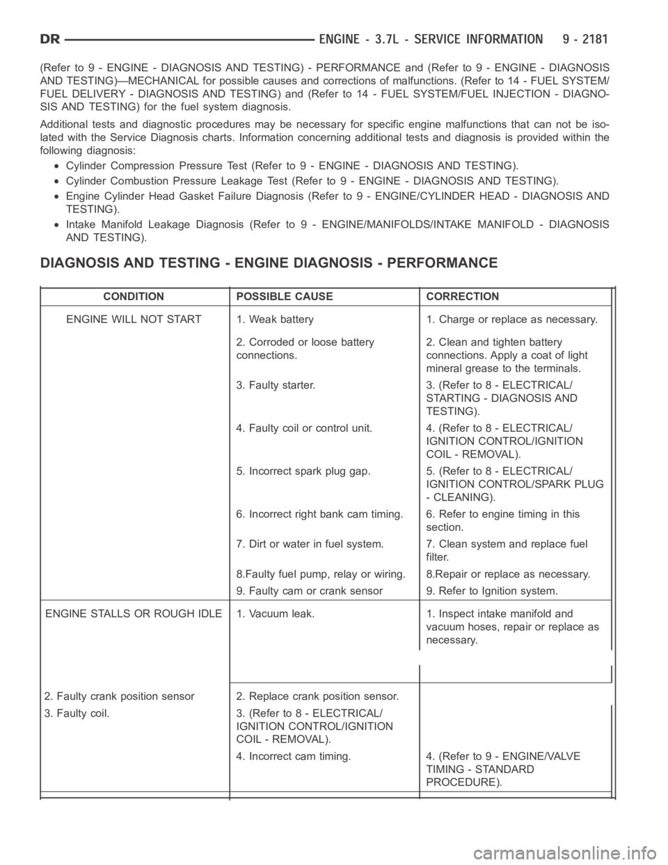
(Refer to 9 - ENGINE - DIAGNOSIS AND TESTING) - PERFORMANCE and (Refer to 9 - ENGINE - DIAGNOSIS
AND TESTING)—MECHANICAL for possible causes and corrections of malfunctions. (Refer to 14 - FUEL SYSTEM/
FUEL DELIVERY - DIAGNOSIS AND TESTING) and (Refer to 14 - FUEL SYSTEM/FUEL INJECTION - DIAGNO-
SIS AND TESTING) for the fuel system diagnosis.
Additional tests and diagnostic procedures may be necessary for specificengine malfunctions that can not be iso-
lated with the Service Diagnosis charts. Information concerning additional tests and diagnosis is provided within the
following diagnosis:
Cylinder Compression Pressure Test (Refer to 9 - ENGINE - DIAGNOSIS AND TESTING).
Cylinder Combustion Pressure LeakageTest (Refer to 9 - ENGINE - DIAGNOSISAND TESTING).
Engine Cylinder Head Gasket Failure Diagnosis (Refer to 9 - ENGINE/CYLINDER HEAD - DIAGNOSIS AND
TESTING).
Intake Manifold Leakage Diagnosis (Refer to 9 - ENGINE/MANIFOLDS/INTAKEMANIFOLD - DIAGNOSIS
AND TESTING).
DIAGNOSIS AND TESTING - ENGINE DIAGNOSIS - PERFORMANCE
CONDITION POSSIBLE CAUSE CORRECTION
ENGINE WILL NOT START 1. Weak battery 1. Charge or replace as necessary.
2. Corroded or loose battery
connections.2. Clean and tighten battery
connections. Apply a coat of light
mineral grease to the terminals.
3. Faulty starter. 3. (Refer to 8 - ELECTRICAL/
STARTING - DIAGNOSIS AND
TESTING).
4. Faulty coil or control unit. 4. (Refer to 8 - ELECTRICAL/
IGNITION CONTROL/IGNITION
COIL - REMOVAL).
5. Incorrect spark plug gap. 5. (Refer to 8 - ELECTRICAL/
IGNITION CONTROL/SPARK PLUG
- CLEANING).
6. Incorrect right bank cam timing. 6. Refer to engine timing in this
section.
7. Dirt or water in fuel system. 7. Clean system and replace fuel
filter.
8.Faulty fuel pump, relay or wiring. 8.Repair or replace as necessary.
9. Faulty cam or crank sensor 9. Refer to Ignition system.
ENGINE STALLS OR ROUGH IDLE 1. Vacuum leak. 1. Inspect intake manifold and
vacuum hoses, repair or replace as
necessary.
2. Faulty crank position sensor 2. Replace crank position sensor.
3. Faulty coil. 3. (Refer to 8 - ELECTRICAL/
IGNITION CONTROL/IGNITION
COIL - REMOVAL).
4. Incorrect cam timing. 4. (Refer to 9 - ENGINE/VALVE
TIMING - STANDARD
PROCEDURE).
Page 1491 of 5267
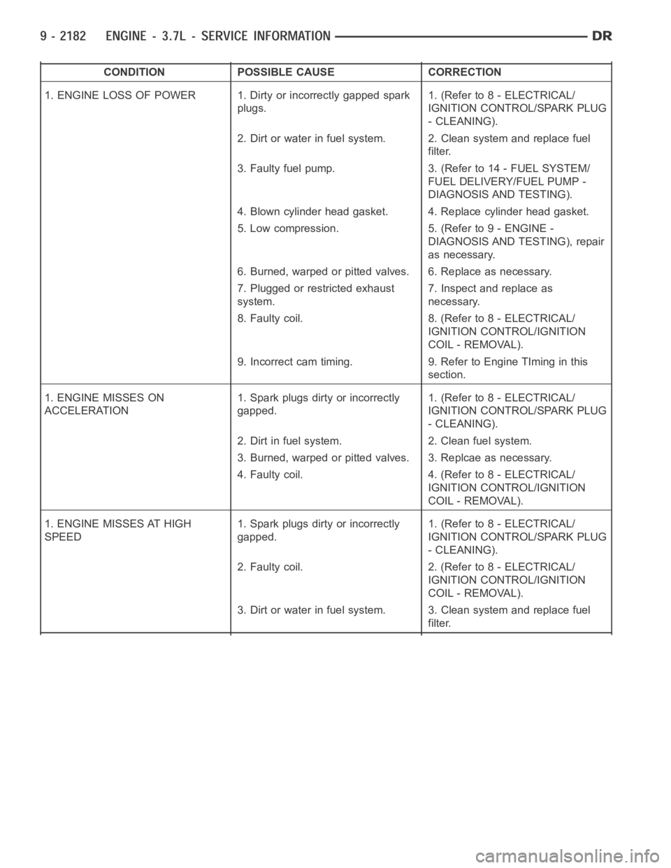
CONDITION POSSIBLE CAUSE CORRECTION
1. ENGINE LOSS OF POWER 1. Dirty or incorrectly gapped spark
plugs.1. (Refer to 8 - ELECTRICAL/
IGNITION CONTROL/SPARK PLUG
- CLEANING).
2. Dirt or water in fuel system. 2. Clean system and replace fuel
filter.
3. Faulty fuel pump. 3. (Refer to 14 - FUEL SYSTEM/
FUEL DELIVERY/FUEL PUMP -
DIAGNOSIS AND TESTING).
4. Blown cylinder head gasket. 4. Replace cylinder head gasket.
5. Low compression. 5. (Refer to 9 - ENGINE -
DIAGNOSIS AND TESTING), repair
as necessary.
6. Burned, warped or pitted valves. 6. Replace as necessary.
7. Plugged or restricted exhaust
system.7. Inspect and replace as
necessary.
8. Faulty coil. 8. (Refer to 8 - ELECTRICAL/
IGNITION CONTROL/IGNITION
COIL - REMOVAL).
9. Incorrect cam timing. 9. Refer to Engine TIming in this
section.
1. ENGINE MISSES ON
ACCELERATION1. Spark plugs dirty or incorrectly
gapped.1. (Refer to 8 - ELECTRICAL/
IGNITION CONTROL/SPARK PLUG
- CLEANING).
2. Dirt in fuel system. 2. Clean fuel system.
3. Burned, warped or pitted valves. 3. Replcae as necessary.
4. Faulty coil. 4. (Refer to 8 - ELECTRICAL/
IGNITION CONTROL/IGNITION
COIL - REMOVAL).
1. ENGINE MISSES AT HIGH
SPEED1. Spark plugs dirty or incorrectly
gapped.1. (Refer to 8 - ELECTRICAL/
IGNITION CONTROL/SPARK PLUG
- CLEANING).
2. Faulty coil. 2. (Refer to 8 - ELECTRICAL/
IGNITION CONTROL/IGNITION
COIL - REMOVAL).
3. Dirt or water in fuel system. 3. Clean system and replace fuel
filter.
Page 1492 of 5267
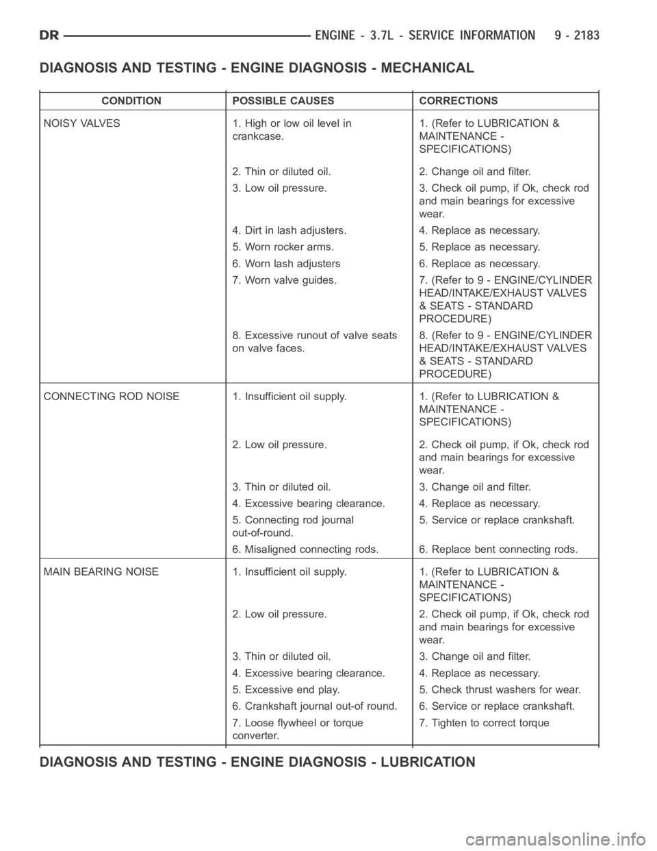
DIAGNOSIS AND TESTING - ENGINE DIAGNOSIS - MECHANICAL
CONDITION POSSIBLE CAUSES CORRECTIONS
NOISY VALVES 1. High or low oil level in
crankcase.1. (Refer to LUBRICATION &
MAINTENANCE -
SPECIFICATIONS)
2. Thin or diluted oil. 2. Change oil and filter.
3. Low oil pressure. 3. Check oil pump, if Ok, check rod
and main bearings for excessive
wear.
4. Dirt in lash adjusters. 4. Replace as necessary.
5. Worn rocker arms. 5. Replace as necessary.
6. Worn lash adjusters 6. Replace as necessary.
7. Worn valve guides. 7. (Refer to 9 - ENGINE/CYLINDER
HEAD/INTAKE/EXHAUST VALVES
& SEATS - STANDARD
PROCEDURE)
8. Excessive runout of valve seats
on valve faces.8. (Refer to 9 - ENGINE/CYLINDER
HEAD/INTAKE/EXHAUST VALVES
& SEATS - STANDARD
PROCEDURE)
CONNECTING ROD NOISE 1. Insufficient oil supply. 1. (Refer to LUBRICATION&
MAINTENANCE -
SPECIFICATIONS)
2. Low oil pressure. 2. Check oil pump, if Ok, check rod
and main bearings for excessive
wear.
3. Thin or diluted oil. 3. Change oil and filter.
4. Excessive bearing clearance. 4. Replace as necessary.
5. Connecting rod journal
out-of-round.5. Service or replace crankshaft.
6. Misaligned connecting rods. 6. Replace bent connecting rods.
MAIN BEARING NOISE 1. Insufficient oil supply. 1. (Refer to LUBRICATION &
MAINTENANCE -
SPECIFICATIONS)
2. Low oil pressure. 2. Check oil pump, if Ok, check rod
and main bearings for excessive
wear.
3. Thin or diluted oil. 3. Change oil and filter.
4. Excessive bearing clearance. 4. Replace as necessary.
5. Excessive end play. 5. Check thrust washers for wear.
6. Crankshaft journal out-of round. 6. Service or replace crankshaft.
7. Loose flywheel or torque
converter.7. Tighten to correct torque
DIAGNOSIS AND TESTING - ENGINE DIAGNOSIS - LUBRICATION