Page 897 of 5267

*INTAKE AIR SYSTEM PRESSURE TEST
Diagnostic Test
1.CHARGE AIR COOLER PRESSURE TEST
Loosen air inlet tube clamp at the turbocharger.
Remove the air filter housing and the inlet tube from the vehicle as an assembly.
Install the CAC Pressure Tester #9022 into the inner diameter of the turbocharger, securing it in place with the
supplied three-fingered band clamp, tighten tool clamp to 8n.m (72 in lbs).
NOTE: NEVER ATTEMPT TO START OR RUN THE VEHICLE AT ANY TIME DURING THIS TEST,ENGINE DAM-
AGE MAY OCCUR.
Fasten the safety chain around a solid surface behind the turbocharger. Warning: Never run CAC Pressure test
without the safety chain securely fastened.
Before attaching shop air to the pressure regulator verify that the regulator is at its lowest pressure setting (0 psi).
Attach an air supply to the regulator and slowly increase the pressure until the pressure gauge reads 20 psi.
WARNING: WARNING: Never apply more than 20 PSI.
Using a solution of soap and water spray the Turbocharger, Turbocharger wastegate, Charge Air Cooler Heat
Exchange and CAC Hoses while watching for leaks.
Before any attempt to repair the CAC system is made, its necessary to completely discharge the system. This can
be accomplished by turning the regulator knob counter-clockwise.
Allow for adequate time to pass before removing the CAC Pressure tester from the turbo charger inlet.
Position the Air Filter Housing over thethreemountingstudslocatedonthe inside front fender well and press down
firmly to lock housing into place.
Install Air Inlet Tube over the Turbocharger inlet and torque the band clampto35in.lbs.
View Repair
Repair
Te s t c o m p l e t e .
Perform POWERTRAIN VERIFICATION TEST VER - 1 (DIESEL). (Refer to 8 - ELECTRICAL/ELEC-
TRONIC CONTROL MODULES/ENGINE CONTROL MODULE - DIAGNOSIS AND TESTING)
Page 1953 of 5267

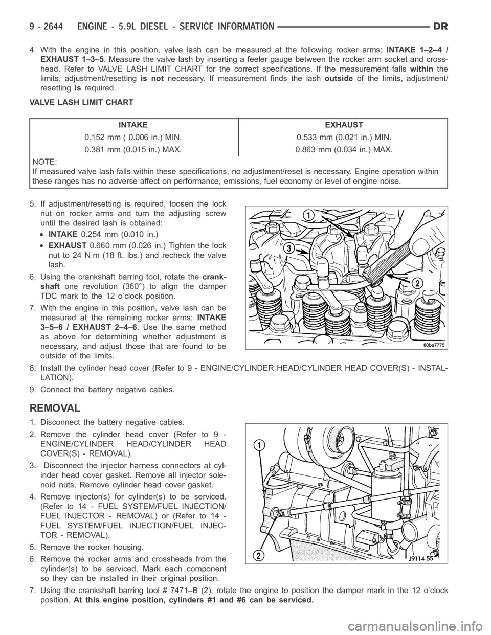
4. With the engine in this position, valve lash can be measured at the following rocker arms:INTAKE 1–2–4 /
EXHAUST 1–3–5. Measure the valve lash by inserting a feeler gauge between the rocker arm socket and cross-
head. Refer to VALVE LASH LIMIT CHART for the correct specifications. If the measurement fallswithinthe
limits, adjustment/resettingis notnecessary. If measurement finds the lashoutsideof the limits, adjustment/
resettingisrequired.
VALVE LASH LIMIT CHART
INTAKE EXHAUST
0.152 mm ( 0.006 in.) MIN. 0.533 mm (0.021 in.) MIN.
0.381 mm (0.015 in.) MAX. 0.863 mm (0.034 in.) MAX.
NOTE:
If measured valve lash falls within these specifications, no adjustment/reset is necessary. Engine operation within
these ranges has no adverse affect on performance, emissions, fuel economy or level of engine noise.
5. If adjustment/resetting is required, loosen the lock
nut on rocker arms and turn the adjusting screw
until the desired lash is obtained:
INTAKE0.254 mm (0.010 in.)
EXHAUST0.660 mm (0.026 in.) Tighten the lock
nut to 24 Nꞏm (18 ft. lbs.) and recheck the valve
lash.
6. Using the crankshaft barring tool, rotate thecrank-
shaftone revolution (360°) to align the damper
TDC mark to the 12 o’clock position.
7. With the engine in this position, valve lash can be
measured at the remaining rocker arms:INTAKE
3–5–6 / EXHAUST 2–4–6. Use the same method
as above for determining whether adjustment is
necessary, and adjust those that are found to be
outside of the limits.
8. Install the cylinder head cover (Refer to 9 - ENGINE/CYLINDER HEAD/CYLINDER HEAD COVER(S) - INSTAL-
LATION).
9. Connect the battery negative cables.
REMOVAL
1. Disconnect the battery negative cables.
2. Remove the cylinder head cover (Refer to 9 -
ENGINE/CYLINDER HEAD/CYLINDER HEAD
COVER(S) - REMOVAL).
3. Disconnect the injector harness connectors at cyl-
inder head cover gasket. Remove all injector sole-
noid nuts. Remove cylinder head cover gasket.
4. Remove injector(s) for cylinder(s) to be serviced.
(Refer to 14 - FUEL SYSTEM/FUEL INJECTION/
FUELINJECTOR-REMOVAL)or(Referto14-
FUEL SYSTEM/FUEL INJECTION/FUEL INJEC-
TOR - REMOVAL).
5. Remove the rocker housing.
6. Remove the rocker arms and crossheads from the
cylinder(s) to be serviced. Mark each component
so they can be installed in their original position.
7. Using the crankshaft barring tool # 7471–B (2), rotate the engine to position the damper mark in the 12 o’clock
position.At this engine position, cylinders #1 and #6 can be serviced.
Page 4019 of 5267

19. Check and adjust gearshift and throttle valve cables, if necessary.
ADJUSTMENTS - VALVE BODY
CONTROL PRESSURE ADJUSTMENTS
There are two control pressure adjustments on the valve body;
Line Pressure
Throttle Pressure
Line and throttle pressures are interdependent because each affects shift quality and timing. As a result, both
adjustments must be performed properly and in the correct sequence. Adjust line pressure first and throttle pressure
last.
LINE PRESSURE ADJUSTMENT
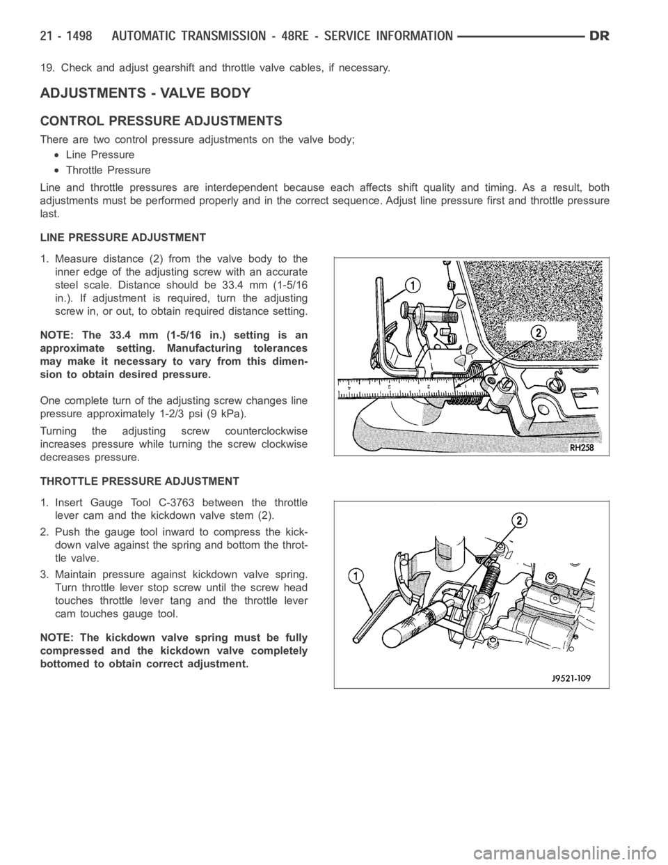
1. Measure distance (2) from the valve body to the
inner edge of the adjusting screw with an accurate
steel scale. Distance should be 33.4 mm (1-5/16
in.). If adjustment is required, turn the adjusting
screw in, or out, to obtain required distance setting.
NOTE: The 33.4 mm (1-5/16 in.) setting is an
approximate setting. Manufacturing tolerances
may make it necessary to vary from this dimen-
sion to obtain desired pressure.
One complete turn of the adjusting screw changes line
pressure approximately 1-2/3 psi (9 kPa).
Turning the adjustingscrew counterclockwise
increases pressure while turning the screw clockwise
decreases pressure.
THROTTLE PRESSURE ADJUSTMENT
1. Insert Gauge Tool C-3763 between the throttle
lever cam and the kickdown valve stem (2).
2. Push the gauge tool inward to compress the kick-
down valve against the spring and bottom the throt-
tle valve.
3. Maintain pressure against kickdown valve spring.
Turn throttle lever stop screw until the screw head
touches throttle lever tang and the throttle lever
cam touches gauge tool.
NOTE: The kickdown valve spring must be fully
compressed and the kickdown valve completely
bottomed to obtain correct adjustment.