2006 DODGE RAM SRT-10 oil reset
[x] Cancel search: oil resetPage 1666 of 5267
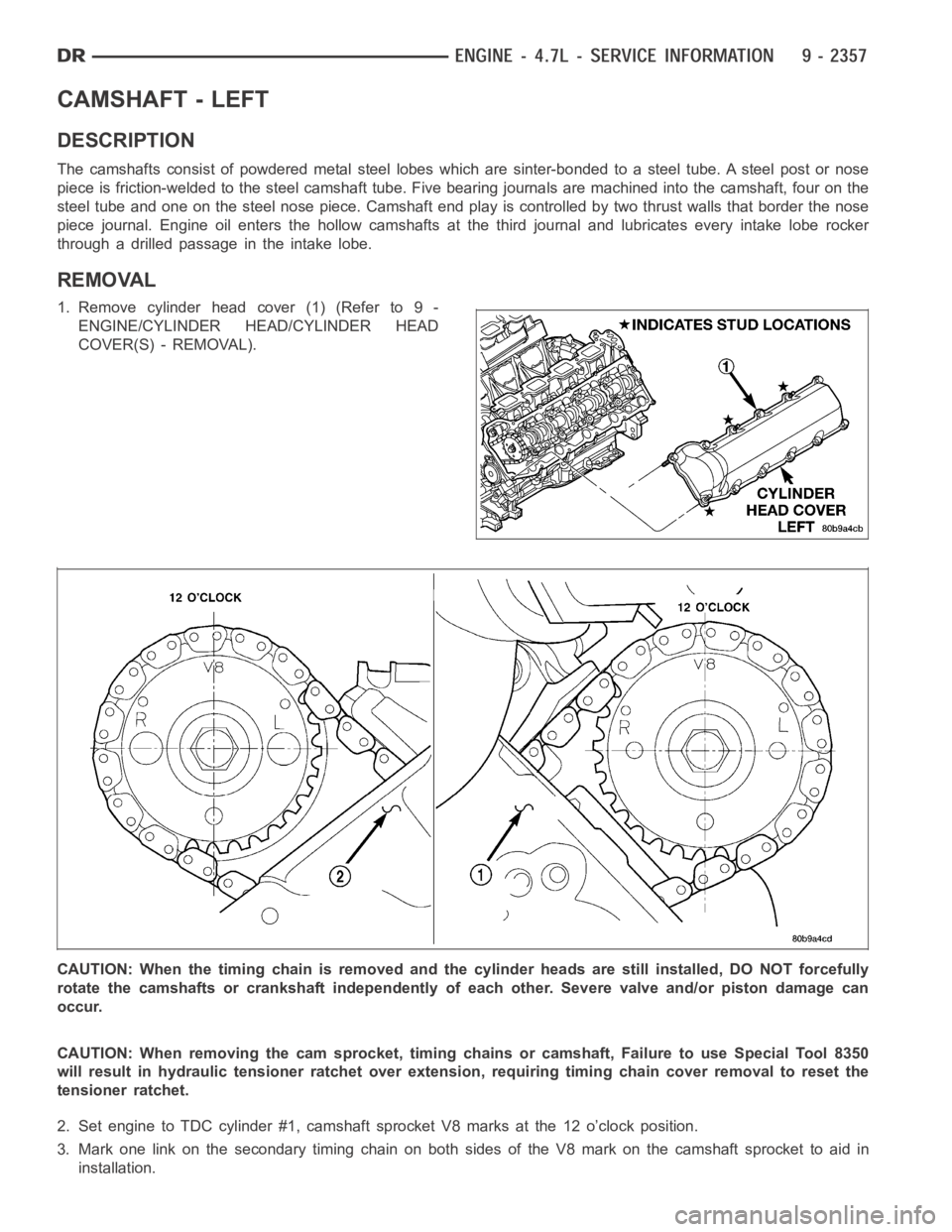
CAMSHAFT - LEFT
DESCRIPTION
The camshafts consist of powdered metal steel lobes which are sinter-bonded to a steel tube. A steel post or nose
piece is friction-welded to the steel camshaft tube. Five bearing journals are machined into the camshaft, four on the
steel tube and one on the steel nose piece. Camshaft end play is controlled by two thrust walls that border the nose
piece journal. Engine oil enters the hollow camshafts at the third journaland lubricates every intake lobe rocker
throughadrilledpassageintheintakelobe.
REMOVAL
1. Remove cylinder head cover (1) (Refer to 9 -
ENGINE/CYLINDER HEAD/CYLINDER HEAD
COVER(S) - REMOVAL).
CAUTION: When the timing chain is removed and the cylinder heads are still installed, DO NOT forcefully
rotate the camshafts or crankshaft independently of each other. Severe valve and/or piston damage can
occur.
CAUTION: When removing the cam sprocket, timing chains or camshaft, Failure to use Special Tool 8350
will result in hydraulic tensioner ratchet over extension, requiring timing chain cover removal to reset the
tensioner ratchet.
2. Set engine to TDC cylinder #1, camshaft sprocket V8 marks at the 12 o’clock position.
3. Mark one link on the secondary timing chain on both sides of the V8 mark on the camshaft sprocket to aid in
installation.
Page 1930 of 5267
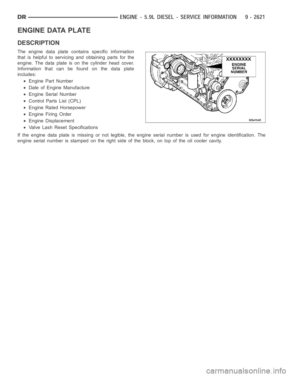
ENGINE DATA PLATE
DESCRIPTION
The engine data plate contains specific information
that is helpful to servicing and obtaining parts for the
engine. The data plate is on the cylinder head cover.
Information that can be found on the data plate
includes:
Engine Part Number
Date of Engine Manufacture
Engine Serial Number
Control Parts List (CPL)
Engine Rated Horsepower
Engine Firing Order
Engine Displacement
Valve Lash Reset Specifications
If the engine data plate is missing or not legible, the engine serial numberis used for engine identification. The
engine serial number is stamped on the right side of the block, on top of the oil cooler cavity.
Page 2816 of 5267
When Monitored:
Continuously while driving in a forward gear.
Set Condition:
The PCM continuously monitors Actual Line Pressure and compares it to DesiredLinePressure.IftheActual
Line Pressure is more than 10 psi below Desired Line Pressure, this DTC willset.
Possible Causes
CHECK FOR RELATED DTC’S
LOW FLUID LEVEL
(F856) 5-VOLT SUPPLY CIRCUIT OPEN
(F856) 5-VOLT SUPPLY CIRCUIT SHORT TO GROUND
(F856) 5-VOLT SUPPLY CIRCUIT SHORT TO VOLTAGE
(T118) PRESSURE CONTROL SOLENOID CONTROL CIRCUIT SHORT TO ANOTHER CIRCUIT
INTERNAL TRANSMISSION
LINE PRESSURE SENSOR
CRACKED, PLUGGED, OR MIS-INSTALLED PRIMARY OIL FILTER
STUCK OR STICKING MAIN REGULATOR VALVE
POWERTRAIN CONTROL MODULE
Always perform the 42RLE Pre-Diagnostic Troubleshooting procedure before proceeding. (Refer to 21 -
TRANSMISSION/TRANSAXLE/AUTOMATIC - 42RLE - STANDARD PROCEDURE)
Theory of Operation
Line pressure is measured by the Line Pressure Sensor (LPS) and regulationis achieved by changing the duty
cycle of the Pressure Control Solenoid (PCS) controlled by the Transmission Control System. (5% duty cycle =
solenoid off = Max line pressure, 62%duty cycle = solenoid on = Min line pressure). The Transmission Control
System calculates the desired line pressure based on inputs from both the engine and transmission.
The Transmission Control System calculates torque input to the transmission and uses it as the primary input to the
desired line pressure calculation. This is called Torque Based Line Pressure. In addition, the line pressure is set to
a preset level 827 or 931 kPa (120 or 135 psi) during shifts and in Park and Neutral to ensure consistent shift
quality. The desired line pressure is continuously being compared to the actual line pressure. If the actual line pres-
sure is consistently lower than the target while driving, the line pressure low DTC P0868 will set.
Diagnostic Test
1.CHECKFORRELATEDDTCS
With the scan tool, check for other transmission DTCs
Is the DTC P0932 present also?
Ye s>>
Refer to the Transmission category and perform the appropriate symptom.
No>>
Go To 2
Page 2850 of 5267
P0897-TRANSMISSION FLUID DETERIORATED
For a complete wiring diagramRefer to Section 8W.
When Monitored:
Each transition from full EMCC to partial EMCC for A/C bump prevention.
Set Condition:
DTC set if 20 occurrences of a turbine acceleration sum. Fault Set Time: 20 transitions from full EMCC to
partial EMCC. Transmission will not use partial EMCC. Established for A/Cbump prevention.
Possible Causes
WORN OUT/ BURNT TRANSAXLE FLUID
Always perform the 42RLE Pre-Diagnostic Troubleshooting procedure before proceeding. (Refer to 21 -
TRANSMISSION/TRANSAXLE/AUTOMATIC - 42RLE - STANDARD PROCEDURE)
Theory of Operation
To prevent a bump due to A/C clutch engagement, a temporary torque converter partial EMCC condition is estab-
lished prior to A/C clutch engagement. A message is received over the bus indicating that A/C clutch engagement
is imminent. Partial EMCC is then established and a reply message,
OK to engage A/C clutchis sent via the bus.
Partial EMCC will be held for 450 ms before returning to full EMCC. During the transition from full to partial EMCC,
a turbine acceleration sum is calculated, if this value exceeds a threshold value for several transitions, degraded
transmission fluid is indicated.
Diagnostic Test
1.WORN OUT/ BURNT TRANSMISSION FLUID
Turn the ignition off to the lock position.
Flush the Transmission Oil Cooler and lines, replace the Transmission OilFilter, refill with new Transmission Fluid,
start the engine, and adjust the fluid per the Service Information.
NOTE: The Transmission Cooler must be flushed before proceeding.
Allow the engine to idle for 10 minutes, in Park.
Turn the ignition off to the lock position.
Again, flush the Transmission Oil Cooler and lines, replace the Transmission Oil Filter, refill with new Transmission
Fluid, start the engine, and adjust the fluid per the Service Information.
With the scan tool, perform a Battery Disconnect.
NOTE: The Battery Disconnect must be done to re-enable EMCC during an A/C Clutch engagement.
NOTE: The vehicle may exhibit intermittent shudder during the first few hundred miles. The new Transmis-
sion Fluid will gradually penetrate the Torque Convertor Clutch frictionmaterial and the shudder should
disappear.
Erase the DTC and return the vehicle to the customer.
Did the DTC reset and/or does the vehicle still shudder after a few thousandmiles?
Ye s>>
Replace the Torque Converter per the Service Information.
Perform 42RLE TRANSMISSION VERIFICATION TEST - VER 1. (Refer to 21 - TRANSMISSION/
TRANSAXLE/AUTOMATIC - 42RLE - STANDARD PROCEDURE)
No>>
Te s t C o m p l e t e .
Page 2892 of 5267
3.CHECK TO SEE IF DTC P1776 IS CURRENT
With the scan tool, check the STARTS SINCE SET counter for P1776.
NOTE: This counter only applies to the last DTC set.
Is the status Active or is the STARTS SINCE SET counter 2 or less for this DTC?
Ye s>>
Go To 4
No>>
Go To 9
4.CHECK THE PCM AND WIRING USING THE TRANSMISSION SIMULATOR
Turn the ignition off to the lock position.
Remove the Ignition Switch Feed fuse from the TIPM.
CAUTION: Removal of the Ignition Switch Feed fuse from the TIPM will prevent the vehicle from being
startedingear.
WARNING: The Ignition Switch Feed fuse must be removed from the TIPM. Failure to do so can result in
personal injury or death.
Install the Transmission Simulator,Miller tool #8333 and the ElectronicTransmission Adapter kit.
Ignition on, engine not running.
With the Transmission Simulator, turn the Pressure Switch selector switchtoL/R.
With the scan tool, monitor the L/R Pressure Switch State while pressing the Pressure Switch Test button.
Did the Pressure Switch state change from open to closed when the test button was pressed?
Ye s>>
Go To 5
No>>
Go To 6
5.CHECK THE SOLENOID SWITCH VALVE FOR STICKING
Remove the transmission oil pan and Valve body and inspect the Solenoid Switch Valve for sticking in its bore,
repair or replace as necessary.
NOTE: This DTC may be caused by debris lodged in the Transmission Solenoid Switch Valve bore. If debris
is found, clean the valve body and reassemble the transmission per the Service Information.
With the scan tool, record the DTC EVENT DATA for P1776 and erase DTCs.
Reassemble the transmission and test drive the vehicle. Try to duplicate the original set conditions using the DTC
EVENT DATA recorded earlier.
With the scan tool, check Transmission DTCs.
Did the DTC P1776 reset?
Ye s>>
Replace the Transmission Solenoid Assembly per the Service Information.
Perform 42RLE TRANSMISSION VERIFICATION TEST - VER 1. (Refer to 21 - TRANSMISSION/
TRANSAXLE/AUTOMATIC - 42RLE - STANDARD PROCEDURE)
No>>
Te s t C o m p l e t e
Perform 42RLE TRANSMISSION VERIFICATION TEST - VER 1. (Refer to 21 - TRANSMISSION/
TRANSAXLE/AUTOMATIC - 42RLE - STANDARD PROCEDURE)
Page 3156 of 5267
14.CHECK FOR BROKEN REVERSE SUN GEAR WELD
Working through the windows in the bottom of the case, check for a broken Reverse Sun gear weld to the reaction
carrier as follows:
1) Hold the Transmission Output Shaft by holding the Transmission Manual Lever in the park position.
2) Rotate the Input Annulus gear and drive shell (the drum that encloses thetwo rearmost carriers).
3) Check to see if the reaction carrier (the front-most carrier, whose outer shell is splined to the 2C clutch) is rotat-
ing faster than the drive shell is being turned.
Is the reaction carrier turning faster than the drive shell?
Ye s>>
Replace Transmission Solenoid/TRS Assembly per the Service Information. (Refer to 21 - TRANSMIS-
SION/TRANSAXLE/AUTOMATIC - 45RFE/545RFE/TRANS SOLENOID/TRS ASSY - REMOVAL)
Perform 45RFE/545RFE TRANSMISSION VERIFICATION TEST - VER 1. (Refer to 21- TRANSMIS-
SION/TRANSAXLE/AUTOMATIC - 45RFE/545RFE - STANDARD PROCEDURE)
No>>
Replace the reaction carrier per the Service Information.
Perform 45RFE/545RFE TRANSMISSION VERIFICATION TEST - VER 1. (Refer to 21- TRANSMIS-
SION/TRANSAXLE/AUTOMATIC - 45RFE/545RFE - STANDARD PROCEDURE)
15.CHECK IF DTC RESETS
Did the DTC P0732 reset during the road test?
Ye s>>
Go To 16
No>>
Go To 17
16.LIST OF POSSIBLE CAUSES
If any other DTCs set during the road test, refer to the appropriate symptomin the Transmission category.
If no other DTCs set during the road test, below is a list of possible causes,but not strictly limited to those:
Check for excessive debris in the Transmission Oil pan, plugged, cracked,or misinstalled Primary Transmis-
sion Oil Filter and/or seal.
Check for cut and/or missing #7 and #5 check balls in the main valve body.
Check the 2C and UD accumulator pistons and seals, UD bleed orifice, and theSolenoid Switch Valve and
Plugs in the main valve body.
Check the UD clutch piston seals, reaction shaft support seal rings and dribbler assembly.
Check the 2C clutch piston seals, and bleed orifice.
Check the main regulator valve for sticking in its bore and the flatness of the pump valve body and pump
housing faces.
Check for a improperly assembled 2C clutch with the thick reaction plate not against the case.
View repair
Repair
Repair as necessary. Refer to the Service Information for proper repair procedures.
Perform 45RFE/545RFE TRANSMISSION VERIFICATION TEST - VER 1. (Refer to 21- TRANSMIS-
SION/TRANSAXLE/AUTOMATIC - 45RFE/545RFE - STANDARD PROCEDURE)
Page 3162 of 5267
14.CHECK FOR NO REVERSE
During the road test on a previous test, did the vehicle have no reverse and no 3rd gear, but 1st and 2nd
gears were OK?
Ye s>>
Go To 15
No>>
Replace Transmission Solenoid/TRS Assembly per the Service Information. (Refer to 21 - TRANSMIS-
SION/TRANSAXLE/AUTOMATIC - 45RFE/545RFE/TRANS SOLENOID/TRS ASSY - REMOVAL)
Perform 45RFE/545RFE TRANSMISSION VERIFICATION TEST - VER 1. (Refer to 21- TRANSMIS-
SION/TRANSAXLE/AUTOMATIC - 45RFE/545RFE - STANDARD PROCEDURE)
15.CHECK FOR BROKEN REVERSE CARRIER WELD
Remove the Transmission per the Service Information and inspect the weld on the reverse carrier hub.
Were there any problems found?
Ye s>>
Repair as necessary.
No>>
Disassemble and inspect the input clutch assembly. Check the OD and Reverse clutch seals, discs, and
bleed orifice (in the OD/Reverse clutch piston). Check the OD hub and shaft. Repair as necessary.
Refer to the Service Information for proper repair procedures.
Perform 45RFE/545RFE TRANSMISSION VERIFICATION TEST - VER 1. (Refer to 21- TRANSMIS-
SION/TRANSAXLE/AUTOMATIC - 45RFE/545RFE - STANDARD PROCEDURE)
16.CHECK IF DTC RESETS
Did the DTC P0733 reset during the road test?
Ye s>>
Go To 17
No>>
Go To 18
17.LIST OF POSSIBLE CAUSES
If any other DTCs set during the road test, refer to the appropriate symptomin the Transmission category.
If no other DTCs set during the road test, below is a list of possible causes,but not strictly limited to those.
Check for:
Excessive debris in the Transmission Oil pan, plugged, cracked, or mis-installed Primary Transmission Oil Fil-
ter and/or seal.
Cut or missing #6 check ball in the main valve body.
OD and UD accumulator pistons and seals and bleed orifices, and the SolenoidSwitchValveandPlugsinthe
main valve body.
OD and UD clutch piston seals, reaction shaft support seal rings and dribbler assemblies, and the flatness of
the pump valve body and pump housing faces.
Main regulator valve for sticking in its bore.
View repair
Repair
Repair as necessary. Refer to the Service Information for proper repair procedures.
Perform 45RFE/545RFE TRANSMISSION VERIFICATION TEST - VER 1. (Refer to 21- TRANSMIS-
SION/TRANSAXLE/AUTOMATIC - 45RFE/545RFE - STANDARD PROCEDURE)
Page 3166 of 5267
6.CHECK TRANSMISSION FOR SLIPPAGE
Erase DTCs and road test the vehicle.
Check the transmission operation in reverse and all forward gears.
During the road test, was there any obvious slippage noted in 4th gear or a runaway during the 3-4
shift?
Ye s>>
Go To 8
No>>
Go To 7
7.CHECK IF DTC RESETS
With the scan tool, check for Transmission DTCs after the road test.
Did the DTC P0734 reset?
Ye s>>
Go To 8
No>>
Te s t C o m p l e t e .
8.CHECK INTERNAL TRANSMISSION
Remove the Transmission Oil Pan and Valve Body per the Service Informationand check for the following:
Excessive debris in the oil pan.
Remove the Valve Body and check if the accumulator cover is intact and the 4Ctower seal is not cut or split.
OD and 4C accumulator pistons for cracks and/or cut seals.
Solenoid Switch Valve and its plugs for stickiness or wear.
Cut or missing #5 and/or #6 check ball.
OD bleed orifice on top of the Valve Body
Air check the OD and 4C hydraulic clutch circuits for excessive leakage. Refer to the Service information.
NOTE: Both the OD and 4C hydraulic clutch circuits contain a small bleed orifice. A small amount of air
leakage is considered normal. The OD hydraulic clutch circuit bleed orifice connects to the Reverse input
clutch hydraulic cavity. A small amount of air leakage into the Reverse hydraulic clutch circuit is considered
normal.
Were there any problems found?
Ye s>>
Repair as necessary. Refer to the Service Information for proper repair procedures.
Perform 45RFE/545RFE TRANSMISSION VERIFICATION TEST - VER 1. (Refer to 21- TRANSMIS-
SION/TRANSAXLE/AUTOMATIC - 45RFE/545RFE - STANDARD PROCEDURE)
No>>
Go To 9
9.CHECK THE TRANSMISSION SOLENOID/TRS ASSEMBLY
Was there no reverse gear during the road test?
Ye s>>
Go To 10
No>>
Replace Transmission Solenoid/TRS Assembly per the Service Information. (Refer to 21 - TRANSMIS-
SION/TRANSAXLE/AUTOMATIC - 45RFE/545RFE/TRANS SOLENOID/TRS ASSY - REMOVAL)
Perform 45RFE/545RFE TRANSMISSION VERIFICATION TEST - VER 1. (Refer to 21- TRANSMIS-
SION/TRANSAXLE/AUTOMATIC - 45RFE/545RFE - STANDARD PROCEDURE)