2006 DODGE RAM SRT-10 torque
[x] Cancel search: torquePage 176 of 5267

3.ENGINE MECHANICAL
Check for any of the following conditions/mechanical problems.
AIR INDUCTION SYSTEM - must be free from leaks
ENGINE VACUUM - must be at least 13 inches in neutral
ENGINE VALVE TIMING - must be within specifications
ENGINE COMPRESSION - must be within specifications
ENGINE EXHAUST SYSTEM - must be free of any restrictions or leaks
ENGINE PCV SYSTEM - must flow freely
TORQUE CONVERTER STALL SPEED - must be within specifications
POWER BRAKE BOOSTER - no internal vacuum leaks
FUEL - must be free of contamination
FUEL INJECTOR - plugged or restricted injector; control wire not connectedtocorrectinjector
Are there any engine mechanical problems?
Ye s>>
Repair as necessary.
Perform the POWERTRAIN VERIFICATION TEST. (Refer to 9 - ENGINE - STANDARD PROCEDURE)
No>>
Go To 4
4.O2 SENSOR
Ignition on, engine not running.
Disconnect the 1/2 O2 Sensor harness connector.
With the scan tool, monitor the 1/2 O2 Sensor voltage.
The O2 Sensor voltage should read 5.0 volts on the scan tool with the
connector disconnected.
Using a jumper wire, jump the (K141) O2 Sensor 1/2 Signal circuit to
the (K904) O2 Return Downstream circuit in the O2 Sensor harness
connector.
NOTE: The voltage should drop from 5.0 volts to 2.5 volts with the
jumper wire in place.
Did the O2 Sensor volts change from 5.0 volts to 2.5 volts?
Ye s>>
Replace the O2 Sensor
Perform the POWERTRAIN VERIFICATION TEST. (Refer to
9 - ENGINE - STANDARD PROCEDURE)
No>>
Go To 5
Page 181 of 5267

3.ENGINE MECHANICAL
Check for any of the following conditions/mechanical problems
AIR INDUCTION SYSTEM - must be free from leaks.
ENGINE VACUUM - must be at least 13 inches in neutral
ENGINE VALVE TIMING - must be within specifications
ENGINE COMPRESSION - must be within specifications
ENGINE EXHAUST SYSTEM - must be free of any restrictions or leaks
ENGINE PCV SYSTEM - must flow freely
TORQUE CONVERTER STALL SPEED - must be within specifications
POWER BRAKE BOOSTER - no internal vacuum leaks
FUEL - must be free of contamination
FUEL INJECTOR - plugged or restricted injector; control wire not connectedtocorrectinjector
Are there any engine mechanical problems?
Ye s>>
Repair as necessary.
Perform the POWERTRAIN VERIFICATION TEST. (Refer to 9 - ENGINE - STANDARD PROCEDURE)
No>>
Go To 4
4.O2 SENSOR
Ignition on, engine not running.
Disconnect the 1/2 O2 Sensor harness connector.
With the scan tool, monitor the 1/2 O2 Sensor voltage.
The O2 Sensor voltage should read 5.0 volts on the scan tool with the
connector disconnected.
Using a jumper wire, jump the (K141) O2 Sensor 1/2 Signal circuit to
the (K904) O2 Return Downstream circuit in the O2 Sensor harness
connector.
NOTE: The voltage should drop from 5.0 volts to 2.5 volts with the
jumper wire in place.
Did the O2 Sensor volts change from 5.0 volts to 2.5 volts?
Ye s>>
Replace the O2 Sensor.
Perform the POWERTRAIN VERIFICATION TEST. (Refer to
9 - ENGINE - STANDARD PROCEDURE)
No>>
Go To 5
Page 187 of 5267

3.ENGINE MECHANICAL
Check for any of the following conditions/mechanical problems.
AIR INDUCTION SYSTEM - must be free from leaks
ENGINE VACUUM - must be at least 13 inches in neutral
ENGINE VALVE TIMING - must be within specifications
ENGINE COMPRESSION - must be within specifications
ENGINE EXHAUST SYSTEM - must be free of any restrictions or leaks
ENGINE PCV SYSTEM - must flow freely
TORQUE CONVERTER STALL SPEED - must be within specifications
POWER BRAKE BOOSTER - no internal vacuum leaks
FUEL - must be free of contamination
FUEL INJECTOR - plugged or restricted injector; control wire not connectedtocorrectinjector
Are there any engine mechanical problems?
Ye s>>
Repair as necessary.
Perform the POWERTRAIN VERIFICATION TEST. (Refer to 9 - ENGINE - STANDARD PROCEDURE)
No>>
Go To 4
4.O2 SENSOR
Ignition on, engine not running.
Disconnect the 2/2 O2 Sensor harness connector.
With the scan tool, monitor the 2/2 O2 Sensor voltage.
The O2 Sensor voltage should read 5.0 volts on the scan tool with the
connector disconnected.
Using a jumper wire, jump the (K243) O2 Sensor 2/2 Signal circuit to
the (K904) O2 Return Downstream circuit in the O2 Sensor harness
connector.
NOTE: The voltage should drop from 5.0 volts to 2.5 volts with the
jumper wire in place.
Did the O2 Sensor volts change from 5.0 volts to 2.5 volts?
Ye s>>
Replace the O2 Sensor
Perform the POWERTRAIN VERIFICATION TEST. (Refer to
9 - ENGINE - STANDARD PROCEDURE)
No>>
Go To 5
Page 192 of 5267

3.ENGINE MECHANICAL
Check for any of the following conditions/mechanical problems.
AIR INDUCTION SYSTEM - must be free from leaks
ENGINE VACUUM - must be at least 13 inches in neutral
ENGINE VALVE TIMING - must be within specifications
ENGINE COMPRESSION - must be within specifications
ENGINE EXHAUST SYSTEM - must be free of any restrictions or leaks
ENGINE PCV SYSTEM - must flow freely
TORQUE CONVERTER STALL SPEED - must be within specifications
POWER BRAKE BOOSTER - no internal vacuum leaks
FUEL - must be free of contamination
FUEL INJECTOR - plugged or restricted injector; control wire not connectedtocorrectinjector
Are there any engine mechanical problems?
Ye s>>
Repair as necessary.
Perform the POWERTRAIN VERIFICATION TEST. (Refer to 9 - ENGINE - STANDARD PROCEDURE)
No>>
Go To 4
4.O2 SENSOR
Ignition on, engine not running.
Disconnect the 2/2 O2 Sensor harness connector.
With the scan tool, monitor the 2/2 O2 Sensor voltage.
The O2 Sensor voltage should read 5.0 volts on the scan tool with the
connector disconnected.
Using a jumper wire, jump the (K243) O2 Signal 2/2 circuit to the
(K904) O2 Return Downstream circuit in the O2 Sensor harness con-
nector.
NOTE: The voltage should drop from 5.0 volts to 2.5 volts with the
jumper wire in place.
Did the O2 Sensor volts change from 5.0 volts to 2.5 volts?
Ye s>>
Replace the O2 Sensor
Perform the POWERTRAIN VERIFICATION TEST. (Refer to
9 - ENGINE - STANDARD PROCEDURE)
No>>
Go To 5
Page 896 of 5267

*INJECTOR RETURN FLOW TEST
Diagnostic Test
1.* INJECTOR RETURN FLOW TEST
1. Operate the engine until the engine is at operating temperature.
2. Remove the banjo connector from the fuel drain tube at the rear of the fuelfilter housing.
3. Install fuel system test fitting (9012) in place of the banjo connector.
4. Remove the vehicle fuel return line from the engine fuel drain tube. Route this hose into a container to catch bled
fuel.
5. Install a piece of fuel line onto the test fitting and into a fuel container or into the fuel tank.
6. Install one end of a test hose onto the fuel drain tube. Place the other endof the test hose into a graduated
cylinder.
7. Start the engine and let it idle for one minute.
8. Measure the amount of fuel in the graduated cylinder.
9. If the flow is less than 180-ml/minute, the test has successfully passed.
10. If the flow is greater than 180 ml/minute, shut off the engine and removeall of the fuel injector supply lines. Re
torque all of the high-pressure connector nuts. Install all of the fuel injector supply lines.
11. Start the engine and idle for one minute. Measure the amount of fuel in the graduated cylinder.
12. If the flow is less than 180ml/minute, the condition has been fixed.
13. If the flow is greater than 180 ml/minute after step 12, shut off the engine and remove the #1 fuel injector supply
line. Re torque the high-pressure connector nut. Cap the #1 fuel port usingtool #9011 on the fuel rail and the #1
high pressure connector.
14. Start the engine. Measure the amount of fuel in the graduated cylinder.
15. If the amount of fuel is less than 180 ml/minute, shut off the engine and remove the #1 high pressure connector
and the #1 fuel injector. Inspect for damage, repair/replace as necessary.
16. If the amount of fuel is not less than 180-ml/minute, repeat steps 14-16for cylinders 2-6.
17. Install all high-pressure connectors, fuel injectors, and fuel injector supply lines. Repeat steps 1-8 to confirm
repair.
SPECIFICATION:Less than 180 ml/minute total fuel return flow
Repair
Te s t C o m p l e t e .
Perform POWERTRAIN VERIFICATION TEST VER - 1 (DIESEL). (Refer to 8 - ELECTRICAL/ELEC-
TRONIC CONTROL MODULES/ENGINE CONTROL MODULE - DIAGNOSIS AND TESTING)
Page 897 of 5267

*INTAKE AIR SYSTEM PRESSURE TEST
Diagnostic Test
1.CHARGE AIR COOLER PRESSURE TEST
Loosen air inlet tube clamp at the turbocharger.
Remove the air filter housing and the inlet tube from the vehicle as an assembly.
Install the CAC Pressure Tester #9022 into the inner diameter of the turbocharger, securing it in place with the
supplied three-fingered band clamp, tighten tool clamp to 8n.m (72 in lbs).
NOTE: NEVER ATTEMPT TO START OR RUN THE VEHICLE AT ANY TIME DURING THIS TEST,ENGINE DAM-
AGE MAY OCCUR.
Fasten the safety chain around a solid surface behind the turbocharger. Warning: Never run CAC Pressure test
without the safety chain securely fastened.
Before attaching shop air to the pressure regulator verify that the regulator is at its lowest pressure setting (0 psi).
Attach an air supply to the regulator and slowly increase the pressure until the pressure gauge reads 20 psi.
WARNING: WARNING: Never apply more than 20 PSI.
Using a solution of soap and water spray the Turbocharger, Turbocharger wastegate, Charge Air Cooler Heat
Exchange and CAC Hoses while watching for leaks.
Before any attempt to repair the CAC system is made, its necessary to completely discharge the system. This can
be accomplished by turning the regulator knob counter-clockwise.
Allow for adequate time to pass before removing the CAC Pressure tester from the turbo charger inlet.
Position the Air Filter Housing over thethreemountingstudslocatedonthe inside front fender well and press down
firmly to lock housing into place.
Install Air Inlet Tube over the Turbocharger inlet and torque the band clampto35in.lbs.
View Repair
Repair
Te s t c o m p l e t e .
Perform POWERTRAIN VERIFICATION TEST VER - 1 (DIESEL). (Refer to 8 - ELECTRICAL/ELEC-
TRONIC CONTROL MODULES/ENGINE CONTROL MODULE - DIAGNOSIS AND TESTING)
Page 1058 of 5267

12.ENGINE MECHANICAL PROBLEM
Check for any of the following conditions/mechanical problems.
AIR INDUCTION SYSTEM - must be free from leaks.
ENGINE VACUUM - must be at least 13 inches in neutral
ENGINE VALVE TIMING - must be within specifications
ENGINE COMPRESSION - must be within specifications
ENGINE EXHAUST SYSTEM - must be free of any restrictions or leaks.
ENGINE PCV SYSTEM - must flow freely
TORQUE CONVERTER STALL SPEED - must be within specifications
POWER BRAKE BOOSTER - no internal vacuum leaks
FUEL - must be free of contamination
FUEL INJECTOR - plugged or restricted injector; control wire not connectedtocorrectinjector
Are there any engine mechanical problems?
Ye s>>
Repair as necessary.
Perform the POWERTRAIN VERIFICATION TEST. (Refer to 9 - ENGINE - STANDARD PROCEDURE)
No>>
Refer to the INTERMITTENT CONDITIONSymptom (Diagnostic Procedure).
Perform the POWERTRAIN VERIFICATION TEST. (Refer to 9 - ENGINE - STANDARD PROCEDURE)
13.O2 SENSOR
NOTE: Wait a minimum of 10 minutes to allow the O2 Sensor to cool down before continuing the test.
Ignition on, engine not running.
Disconnect the harness connector(s) of the O2 Sensor(s) that had a voltagereading below 4.5 volts in the previous
step.
With the scan tool, monitor the O2 Sensor voltage reading(s).
Is the voltage above 4.5 volts for any of the O2 Sensors?
Ye s>>
Replace the O2 Sensor that had a voltage reading above 4.5 volts.
Perform the POWERTRAIN VERIFICATION TEST. (Refer to 9 - ENGINE - STANDARD PROCEDURE)
No>>
Go To 14
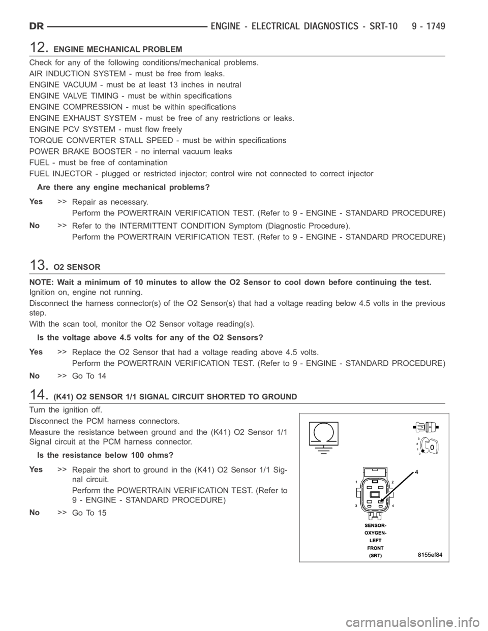
14.(K41) O2 SENSOR 1/1 SIGNAL CIRCUIT SHORTED TO GROUND
Turn the ignition off.
Disconnect the PCM harness connectors.
Measure the resistance between ground and the (K41) O2 Sensor 1/1
Signal circuit at the PCM harness connector.
Istheresistancebelow100ohms?
Ye s>>
Repair the short to ground in the (K41) O2 Sensor 1/1 Sig-
nal circuit.
Perform the POWERTRAIN VERIFICATION TEST. (Refer to
9 - ENGINE - STANDARD PROCEDURE)
No>>
Go To 15
Page 1064 of 5267

9.ECT SENSOR OPERATION
NOTE: For this test to be valid, the thermostat must be operating correctly.
NOTE: This test works best if performed on a cold engine (cold soak)
Ignition on, engine not running.
With the scan tool, read the Engine Coolant Temperature Sensor value. If theenginewasallowedtositovernight
(cold soak), the temperature value should be a sensible value that is somewhere close to the ambient temperature.
NOTE: If engine coolant temperature is above 82°C (180°F), allow the engine to cool until 65°C (150°F) is
reached.
Start the Engine.
During engine warm-up, monitor the Engine Coolant Temperature value. Thetemp value change should be a
smooth transition from start up to normal operating temp 82°C (180°F). Thevalue should reach at least 82°C
(180°F).
Did the Engine Coolant Temperature value increase smoothly and reach at least 82°C?
Ye s>>
Go To 10
No>>
Replace the Engine Coolant Temperature Sensor.
Perform the POWERTRAIN VERIFICATION TEST. (Refer to 9 - ENGINE - STANDARD PROCEDURE)
10.ENGINE MECHANICAL PROBLEM
Check for any of the following conditions/mechanical problems.
AIR INDUCTION SYSTEM - must be free from restrictions.
ENGINE VACUUM - must be at least 13 inches in neutral
ENGINE VALVE TIMING - must be within specifications
ENGINE COMPRESSION - must be within specifications
ENGINE EXHAUST SYSTEM - must be free of any restrictions or leaks.
ENGINE PCV SYSTEM - must flow freely
TORQUE CONVERTER STALL SPEED - must be within specifications
POWER BRAKE BOOSTER - no internal vacuum leaks
FUEL - must be free of contamination
FUEL INJECTOR - plugged or restricted injector; control wire not connectedtocorrectinjector
Are there any engine mechanical problems?
Ye s>>
Repair as necessary.
Perform the POWERTRAIN VERIFICATION TEST. (Refer to 9 - ENGINE - STANDARD PROCEDURE)
No>>
Refer to the INTERMITTENT CONDITION Diagnostic Procedure.
Perform the POWERTRAIN VERIFICATION TEST. (Refer to 9 - ENGINE - STANDARD PROCEDURE)
11 .O2 SENSOR
Disconnect the sensor harness connector of the O2 Sensor(s) that had a voltage value greater than 4.5 volts in the
previous step.
Ignition on, engine not running.
With the scan tool, monitor the O2 Sensor voltage reading(s).
Is the O2 Sensor voltage above 4.5 volts?
Ye s>>
Replace the O2 Sensor.
Perform the POWERTRAIN VERIFICATION TEST. (Refer to 9 - ENGINE - STANDARD PROCEDURE)
No>>
Go To 12