2006 DODGE RAM SRT-10 engine overheat
[x] Cancel search: engine overheatPage 197 of 5267
When Monitored:
With the ignition on and the ETC Motor is not in Limp Home mode.
Set Condition:
When the PCM detects an internal error or a short between the ETC Motor - and ETC Motor + circuits in the
ETC Motor Driver. One trip fault. ETC light is flashing.
Possible Causes
THROTTLE PLATE / BORE INSPECTION
(K447) ETC POSITIVE CIRCUIT SHORTED TO BATTERY VOLTAGE
(K448) ETC NEGATIVE CIRCUIT SHORTED TO BATTERY VOLTAGE
(K447) ETC POSITIVE CIRCUIT SHORTED TO THE (K448) ETC NEGATIVE CIRCUIT
(K447) ETC POSITIVE CIRCUIT OPEN
(K447) ETC POSITIVE CIRCUIT SHORTED TO GROUND
(K448) ETC NEGATIVE CIRCUIT OPEN
(K448) ETC NEGATIVE CIRCUIT SHORTED TO GROUND
LOW BATTERY VOLTAGE
ETC MOTOR/THROTTLE BODY
PCM
Always perform the Pre-Diagnostic Troubleshooting procedure before proceeding. (Refer to 9 - ENGINE -
DIAGNOSIS AND TESTING).
Diagnostic Test
1.ACTIVE DTC
Ignition on, engine not running.
NOTE: If the P2100 is intermittent, it is possible that the controller is overheating in extreme hot tempera-
tures, and this is considered a normal protection operation. No repair is necessary.
NOTE: Low battery voltage can also cause excessive current draw, in very hot and very cold ambient tem-
peratures. Make sure the battery can pass a load test before continuing.
With a scan tool, read DTCs.
Look closely at the temperatures at which this DTC set.
Is the DTC active at this time?
Ye s>>
Go To 2
No>>
Refer to the INTERMITTENT CONDITION Diagnostic Procedure.
Perform the POWERTRAIN VERIFICATION TEST. (Refer to 9 - ENGINE - STANDARD PROCEDURE)
2.THROTTLE PLATE INSPECTION
Turn the ignition off.
Remove the Air Cleaner Assembly from the Throttle Body.
Check for any signs of a foreign material (ice or dirt) on the Throttle Plateor in the bore causing the Throttle Plate
to stick.
Were any signs of foreign material or scoring of the throttle plate or bore found?
Ye s>>
Remove the debris if possible or replace the Throttle Body Assembly. Disconnect the Battery when
replacing the Throttle Body Assembly. After installation is complete, use a scan tool and select the ETC
RELEARN function.
Perform the POWERTRAIN VERIFICATION TEST. (Refer to 9 - ENGINE - STANDARD PROCEDURE)
No>>
Go To 3
Page 224 of 5267
When Monitored:
With the ignition on and the ETC Motor is not in Limp Home mode.
Set Condition:
When the PCM detects an internal error or a short between the ETC Motor - and ETC Motor + circuits in the
ETC Motor Driver. One trip fault. ETC light is flashing.
Possible Causes
THROTTLE PLATE / BORE INSPECTION
(K447) ETC POSITIVE CIRCUIT SHORTED TO BATTERY VOLTAGE
(K448) ETC NEGATIVE CIRCUIT SHORTED TO BATTERY VOLTAGE
(K447) ETC POSITIVE CIRCUIT SHORTED TO THE (K448) ETC NEGATIVE CIRCUIT
(K447) ETC POSITIVE CIRCUIT OPEN
(K447) ETC POSITIVE CIRCUIT SHORTED TO GROUND
(K448) ETC NEGATIVE CIRCUIT OPEN
(K448) ETC NEGATIVE CIRCUIT SHORTED TO GROUND
ETC MOTOR
PCM
Always perform the Pre-Diagnostic Troubleshooting procedure before proceeding. (Refer to 9 - ENGINE -
DIAGNOSIS AND TESTING).
Diagnostic Test
1.ACTIVE DTC
Ignition on, engine not running.
NOTE: If the P2118 is intermittent, it is possible that the controller is overheating in extreme hot tempera-
tures, and this is considered a normal protection operation. No repair is necessary.
With a scan tool, read DTCs.
Look closely at the temperatures at which this DTC set.
Is the DTC active at this time?
Ye s>>
Go To 2
No>>
Refer to the INTERMITTENT CONDITION Diagnostic Procedure.
Perform the POWERTRAIN VERIFICATION TEST. (Refer to 9 - ENGINE - STANDARD PROCEDURE)
2.THROTTLE PLATE INSPECTION
Turn the ignition off.
Remove the Air Cleaner Assembly from the Throttle Body.
Check for any signs of a foreign material (ice or dirt) on the Throttle Plateor in the bore causing the Throttle Plate
to stick.
Were any signs of foreign material or scoring of the throttle plate or bore found?
Ye s>>
Remove the debris if possible or replace the Throttle Body Assembly. Disconnect the Battery when
replacing the Throttle Body Assembly. After installation is complete, use a scan tool and select the ETC
RELEARN function.
Perform the POWERTRAIN VERIFICATION TEST. (Refer to 9 - ENGINE - STANDARD PROCEDURE)
No>>
Go To 3
Page 455 of 5267

page page
ENGINE - ELECTRICAL DIAGNOSTICS -
DIESEL
DIAGNOSIS AND TESTING
PRE-DIAGNOSTIC TROUBLESHOOTING
PROCEDURE............................. 1150
POWERTRAIN VERIFICATION TEST VER - 1
(DIESEL)................................. 1152
POWERTRAIN VERIFICATION TEST VER - 2
(DIESEL)................................. 1153
POWERTRAIN VERIFICATION TEST VER - 4
(DIESEL)................................. 1154
POWERTRAIN VERIFICATION TEST VER - 5
(DIESEL)................................. 1156
INTERMITTENT CONDITION ............... 1157
P0016-ENGINE SPEED SIGNAL MISMATCH . 1158
P0069-BOOST KEY ON RATIONALITY ...... 1160
P0071-INLET AIR TEMP SENSOR
RATIONALITY............................ 1163
P0072-INLET AIR TEMP SENSOR VOLTAGE
TOO LOW................................ 1165
P0073-INLET AIR TEMP SENSOR VOLTAGE
TOO HIGH............................... 1169
P0088-FUEL RAIL PRESSURE SIGNAL IS
ABOVE MAX LIMIT........................ 1174
P0106-INLET AIR PRESSURE SENSOR
RATIONALITY............................ 1176
P0107-INLET AIR PRESSURE SENSOR
VOLTAGE TOO LOW...................... 1178
P0108-INLET AIR PRESSURE SENSOR
VOLTAGE TOO HIGH...................... 1183
P0111-INTAKE AIR TEMPERATURE (IAT)
SENSOR RATIONALITY................... 1188
P0112-INTAKE AIR TEMPERATURE (IAT)
SENSOR VOLTAGE TOO LOW............. 1190
P0113-INTAKE AIR TEMPERATURE (IAT)
SENSOR VOLTAGE TOO HIGH............. 1195
P0116-ENGINE COOLANT TEMPERATURE
(ECT) SENSOR RATIONALITY............. 1200
P0117-ENGINE COOLANT TEMPERATURE
(ECT) SENSOR VOLTAGE TOO LOW....... 1202
P0118-ENGINE COOLANT TEMPERATURE
(ECT) SENSOR VOLTAGE TOO HIGH...... 1206
P0128-THERMOSTAT RATIONALITY ........ 1211
P0148-HIGH PRESSURE COMMON RAIL
(HPCR) CHECKSUM...................... 1212
P0169-WATER IN FUEL (WIF) LIGHT ON
TOO LONG............................... 1215
P0191-FUEL RAIL PRESSURE SENSOR
PERFORMANCE.......................... 1217
P0192-FUEL PRESSURE SENSOR
VOLTAGE TOO LOW...................... 1219P0193-FUEL PRESSURE SENSOR
VOLTAGE TOO HIGH...................... 1224
P0201-INJECTOR #1 CONTROL CIRCUIT . . . 1229
P0202-INJECTOR #2 CONTROL CIRCUIT . . . 1233
P0203-INJECTOR #3 CONTROL CIRCUIT . . . 1237
P0204-INJECTOR #4 CONTROL CIRCUIT . . . 1241
P0205-INJECTOR #5 CONTROL CIRCUIT . . . 1245
P0206-INJECTOR #6 CONTROL CIRCUIT . . . 1249
P0217-DECREASED ENGINE
PERFORMANCE DUE TO ENGINE
OVERHEAT CONDITION................... 1253
P0219-CRANKSHAFT POSITION SENSOR
OVER SPEED SIGNAL.................... 1255
P0234-TURBOCHARGER OVERBOOST
CONDITION.............................. 1257
P0236-MAP SENSOR TOO HIGH
TOO LONG............................... 1259
P0237-MAP SENSOR VOLTAGE TOO LOW . 1261
P0238-MAP SENSOR VOLTAGE TOO HIGH . 1266
P0243-WASTEGATE PRESSURE CONTROL
PWM.................................... 1271
P0251-CP3 PUMP REGULATOR CONTROL . 1277
P0299-BOOST IN RANGE LOW ............ 1283
P0300-MULTIPLE CYLINDER MISFIRE ..... 1286
P0301-CYLINDER # 1 MISFIRE ............ 1289
P0302-CYLINDER # 2 MISFIRE ............ 1292
P0303-CYLINDER # 3 MISFIRE ............ 1295
P0304-CYLINDER # 4 MISFIRE ............ 1298
P0305-CYLINDER # 5 MISFIRE ............ 1301
P0306-CYLINDER # 6 MISFIRE ............ 1304
P0335-CRANKSHAFT POSITION (CKP)
LOST.................................... 1307
P0336-CRANKSHAFT POSITION (CKP)
SENSOR SIGNAL......................... 1313
P0337-CRANKSHAFT POSITION (CKP)
SENSOR VOLTAGE TOO LOW............. 1319
P0338-CRANKSHAFT POSITION (CKP)
SENSOR VOLTAGE TOO HIGH............ 1322
P0340-CAMSHAFT POSITION (CMP) LOST . 1324
P0341-CAMSHAFT POSITION (CMP)
SENSOR SIGNAL......................... 1330
P0381-WAIT TO START LAMP
INOPERATIVE............................ 1336
P0461-FUEL LEVEL UNIT NO CHANGE
OVER TIME.............................. 1338
P0462-LOW VOLTAGE DETECTED AT THE
FUEL LEVEL SENSOR.................... 1341
P0463-HIGH VOLTAGE DETECTED AT THE
FUEL LEVEL SENSOR.................... 1345
P0477-LOW VOLTAGE ON THE ENGINE
BRAKE DRIVER.......................... 1348
Page 562 of 5267
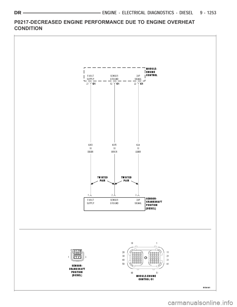
P0217-DECREASED ENGINE PERFORMANCE DUE TO ENGINE OVERHEAT
CONDITION
Page 1263 of 5267
2.VISUALLY INSPECT CATALYTIC CONVERTER
Inspect the Catalytic Converter for the following damage.
Damaged Catalytic Converter, dents or holes.
Severe discoloration caused by overheating the Catalytic Converter.
Catalytic Converter broken internally.
Leaking Catalytic Converter.
Were any problems found?
Ye s>>
Replace the Catalytic Converter. Repair the condition that may have caused the failure.
Perform the POWERTRAIN VERIFICATION TEST. (Refer to 9 - ENGINE - STANDARD PROCEDURE)
No>>
Go To 3
3.EXHAUST LEAK
Start the engine.
Inspect the exhaust for leaks between the engine and the 1/1 O2 Sensor.
Inspect the exhaust for leaks between the engine and the 1/2 O2 Sensor.
Are there any exhaust leaks?
Ye s>>
Repair or replace the leaking exhaust parts as necessary.
Perform the POWERTRAIN VERIFICATION TEST. (Refer to 9 - ENGINE - STANDARD PROCEDURE)
No>>
Go To 4
4.ENGINE MECHANICAL
Check the exhaust for excessive smoke caused by an internal problem in the engine.
Is an engine mechanical condition present?
Ye s>>
Repair the engine mechanical condition as necessary.
Perform the POWERTRAIN VERIFICATION TEST. (Refer to 9 - ENGINE - STANDARD PROCEDURE)
No>>
Go To 5
5.AGING O2 SENSOR
A new rear O2 Sensor along with an aging front O2 Sensor may cause the DTC to set.
Review the vehicles repair history.
Has the rear O2 Sensor been replaced without replacing the front O2 Sensor?
Ye s>>
Replace the Front O2 Sensor as necessary.
Perform the POWERTRAIN VERIFICATION TEST. (Refer to 9 - ENGINE - STANDARD PROCEDURE)
No>>
Go To 6
6.CATALYTIC CONVERTER
If there are no possible cause remaining, view repair.
Repair
Replace the Catalytic Converter.
Perform the POWERTRAIN VERIFICATION TEST. (Refer to 9 - ENGINE - STANDARD PROCEDURE)
Page 1265 of 5267

Theory of Operation
The upstream O2 sensor is used to detect the amount of oxygen in the exhaust gas before the gas enters the
catalytic converter. During the catalyst/O2 monitor test, the response rate (cycles/second) of the upstream O2 sen-
sor determines the sensor’s ability to achieve the tailpipe emissions limits. The response rate of the downstream O2
sensor relative to the upstream O2 sensor response rate measures the catalyst’s ability to store oxygen and is used
to infer the catalyst’s ability to achieve the tailpipe emissions limits.
When Monitored:
After engine warm up to 147 deg. F, 180 seconds of open throttle operation, at a speed greater than 20 mph,
with the engine at 1200-1700 rpm and MAP vacuum between 15.0 and 21.0 inchesof mercury (Hg).
Set Condition:
As catalyst efficiency deteriorates, the switch rate of the downstream O2sensor approaches that of the
upstream O2 sensor. If at any point during the test the switch ratio reachesa predetermined value a counter
is incremented by one. Three good trips to turn off the MIL.
Possible Causes
EXHAUST LEAK
ENGINE MECHANICAL
AGING O2 SENSOR
CATALYTIC CONVERTER
Always perform the Pre-Diagnostic Troubleshooting procedure before proceeding. (Refer to 9 - ENGINE -
DIAGNOSIS AND TESTING).
Diagnostic Test
1.ACTIVE DTC
NOTE: A new rear O2 Sensor along with an aging front O2 Sensor may cause the DTCtoset.Reviewthe
repair history of the vehicle before continuing.
NOTE: If an O2 Sensor DTC set along with the Catalytic Converter EfficiencyDTC diagnose the O2 Sensor
DTC(s) before continuing.
NOTE: Check for contaminants that may have damaged the O2 Sensor and Catalytic Converter: contami-
nated fuel, unapproved silicone, oil and coolant, repair necessary.
Ignition on, engine not running.
With a scan tool, read DTCs.
Is the DTC active at this time?
Ye s>>
Go To 2
No>>
Refer to the INTERMITTENT CONDITION Diagnostic Procedure.
Perform the POWERTRAIN VERIFICATION TEST. (Refer to 9 - ENGINE - STANDARD PROCEDURE)
2.VISUALLY INSPECT CATALYTIC CONVERTER
Inspect the Catalytic Converter for the following damage.
Damaged Catalytic Converter, dents or holes.
Severe discoloration caused by overheating the Catalytic Converter.
Catalytic Converter broken internally.
Leaking Catalytic Converter.
Were any problems found?
Ye s>>
Replace the Catalytic Converter. Repair the condition that may have caused the failure.
Perform the POWERTRAIN VERIFICATION TEST. (Refer to 9 - ENGINE - STANDARD PROCEDURE)
No>>
Go To 3
Page 1517 of 5267
HEAD-CYLINDER-LEFT
DIAGNOSIS AND TESTING - CYLINDER HEAD GASKET
A cylinder head gasket leak can be located between adjacent cylinders or between a cylinder and the adjacent
water jacket.
Possible indications of the cylinder head gasket leaking between adjacent cylinders are:
Loss of engine power
Engine misfiring
Poor fuel economy
Possible indications of the cylinder head gasket leaking between a cylinder and an adjacent water jacket are:
Engine overheating
Loss of coolant
Excessive steam (white smoke) emitting from exhaust
Coolant foaming
CYLINDER-TO-CYLINDER LEAKAGE TEST
To determine if an engine cylinder head gasket is leaking between adjacentcylinders, follow the procedures in Cyl-
inder Compression Pressure Test (Refer to 9 - ENGINE - DIAGNOSIS AND TESTING). An engine cylinder head
gasket leaking between adjacent cylinders will result in approximately a50 - 70% reduction in compression pres-
sure.
CYLINDER-TO-WATER JACKET LEAKAGE TEST
WARNING: USE EXTREME CAUTION WHEN THE ENGINE IS OPERATING WITH COOLANT PRESSURE CAP
REMOVED.
VISUAL TEST METHOD
With the engine cool, remove the coolant pressure cap. Start the engine andallow it to warm up until thermostat
opens.
If a large combustion/compression pressure leak exists, bubbles will be visible in the coolant.
COOLING SYSTEM TESTER METHOD
WARNING: WITH COOLING SYSTEM TESTER IN PLACE, PRESSURE WILL BUILD UP FAST.EXCESSIVE
PRESSURE BUILT UP, BY CONTINUOUS ENGINE OPERATION, MUST BE RELEASED TO A SAFE PRESSURE
POINT. NEVER PERMIT PRESSURE TO EXCEED 138 kPa (20 psi).
Install Cooling System Tester 7700 or equivalent to pressure cap neck. Start the engine and observe the tester’s
pressure gauge. If gauge pulsates with every power stroke of a cylinder a combustion pressure leak is evident.
CHEMICAL TEST METHOD
Combustion leaks into the cooling system can also be checked by using Bloc-Chek Kit C-3685-A or equivalent.
Perform test following the procedures supplied with the tool kit.
REMOVAL
1. Disconnect the negative cable from the battery.
2. Raise the vehicle on a hoist.
3. Disconnect the exhaust pipe at the left side exhaust manifold.
4. Drain the engine coolant (Refer to 7 - COOLING - STANDARD PROCEDURE).
5. Lower the vehicle.
6. Remove the intake manifold (Refer to 9 - ENGINE/MANIFOLDS/INTAKE MANIFOLD - REMOVAL).
Page 1653 of 5267
CYLINDER HEAD
DESCRIPTION
DESCRIPTION - CYLINDER HEAD
The cylinder heads are made of an aluminum alloy. The cylinder head features two valves per cylinder with pressed
in powdered metal valve guides. The cylinder heads also provide enclosures for the timing chain drain, necessitating
unique left and right cylinder heads.
DESCRIPTION - VALVE GUIDES
The valve guides are made of powered metal and are pressed into the cylinderhead. The guides are not replace-
able or serviceable, and valve guide reaming is not recommended. If the guides are worn beyond acceptable limits,
replace the cylinder heads.
DIAGNOSIS AND TESTING
CYLINDER HEAD GASKET
A cylinder head gasket leak can be located between adjacent cylinders or between a cylinder and the adjacent
water jacket.
Possible indications of the cylinder head gasket leaking between adjacent cylinders are:
Loss of engine power
Engine misfiring
Poor fuel economy
Possible indications of the cylinder head gasket leaking between a cylinder and an adjacent water jacket are:
Engine overheating
Loss of coolant
Excessive steam (white smoke) emitting from exhaust
Coolant foaming
CYLINDER-TO-CYLINDER LEAKAGE TEST
To determine if an engine cylinder head gasket is leaking between adjacentcylinders, follow the procedures in Cyl-
inder Compression Pressure Test (Refer to 9 - ENGINE - DIAGNOSIS AND TESTING). An engine cylinder head
gasket leaking between adjacent cylinders will result in approximately a50 - 70% reduction in compression pres-
sure.
CYLINDER-TO-WATER JACKET LEAKAGE TEST
WARNING: USE EXTREME CAUTION WHEN THE ENGINE IS OPERATING WITH COOLANT PRESSURE CAP
REMOVED.
VISUAL TEST METHOD
With the engine cool, remove the coolant pressure cap. Start the engine andallow it to warm up until thermostat
opens.
If a large combustion/compression pressure leak exists, bubbles will be visible in the coolant.
COOLING SYSTEM TESTER METHOD
WARNING: WITH COOLING SYSTEM TESTER IN PLACE, PRESSURE WILL BUILD UP FAST.EXCESSIVE
PRESSURE BUILT UP, BY CONTINUOUS ENGINE OPERATION, MUST BE RELEASED TO A SAFE PRESSURE
POINT. NEVER PERMIT PRESSURE TO EXCEED 138 kPa (20 psi).