2006 DODGE RAM SRT-10 weight
[x] Cancel search: weightPage 1505 of 5267
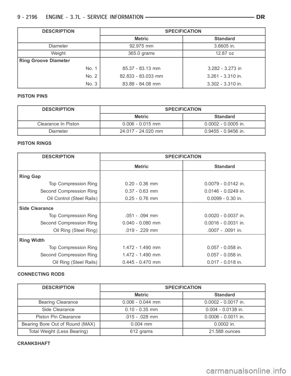
DESCRIPTION SPECIFICATION
Metric Standard
Diameter 92.975 mm 3.6605 in.
Weight 365.0 grams 12.87 oz
Ring Groove Diameter
No. 1 85.37 - 83.13 mm 3.282 - 3.273 in
No. 2 82.833 - 83.033 mm 3.261 - 3.310 in.
No. 3 83.88 - 84.08 mm 3.302 - 3.310 in.
PISTON PINS
DESCRIPTION SPECIFICATION
Metric Standard
Clearance In Piston 0.006 - 0.015 mm 0.0002 - 0.0005 in.
Diameter 24.017 - 24.020 mm 0.9455 - 0.9456 in.
PISTON RINGS
DESCRIPTION SPECIFICATION
Metric Standard
Ring Gap
Top Compression Ring 0.20 - 0.36 mm 0.0079 - 0.0142 in.
Second Compression Ring 0.37 - 0.63 mm 0.0146 - 0.0249 in.
Oil Control (Steel Rails) 0.25 - 0.76 mm 0.0099 - 0.30 in.
Side Clearance
Top Compression Ring .051 - .094 mm 0.0020 - 0.0037 in.
Second Compression Ring 0.040 - 0.080 mm 0.0016 - 0.0031 in.
Oil Ring (Steel Ring) .019 - .229 mm .0007 - .0091 in.
Ring Width
Top Compression Ring 1.472 - 1.490 mm 0.057 - 0.058 in.
Second Compression Ring 1.472 - 1.490 mm 0.057 - 0.058 in.
Oil Ring (Steel Rails) 0.445 - 0.470 mm 0.017 - 0.018 in.
CONNECTING RODS
DESCRIPTION SPECIFICATION
Metric Standard
Bearing Clearance 0.006 - 0.044 mm 0.0002 - 0.0017 in.
Side Clearance 0.10 - 0.35 mm 0.004 - 0.0138 in.
Piston Pin Clearance .015 - .028 mm 0.0006 - 0.0011 in.
Bearing Bore Out of Round (MAX) 0.004 mm 0.0002 in.
Total Weight (Less Bearing) 612 grams 21.588 ounces
CRANKSHAFT
Page 1555 of 5267
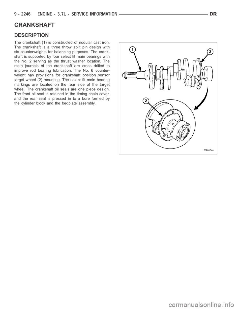
CRANKSHAFT
DESCRIPTION
The crankshaft (1) is constructed of nodular cast iron.
The crankshaft is a three throw split pin design with
six counterweights for balancing purposes. The crank-
shaft is supported by four select fit main bearings with
the No. 2 serving as the thrust washer location. The
main journals of the crankshaft are cross drilled to
improve rod bearing lubrication. The No. 6 counter-
weight has provisions for crankshaft position sensor
target wheel (2) mounting. The select fit main bearing
markings are located on the rear side of the target
wheel. The crankshaft oil seals are one piece design.
The front oil seal is retained in the timing chain cover,
and the rear seal is pressed in to a bore formed by
the cylinder block and the bedplate assembly.
Page 1560 of 5267
BEARINGS-CRANKSHAFT MAIN
STANDARD PROCEDURE
MAIN BEARING FITTING
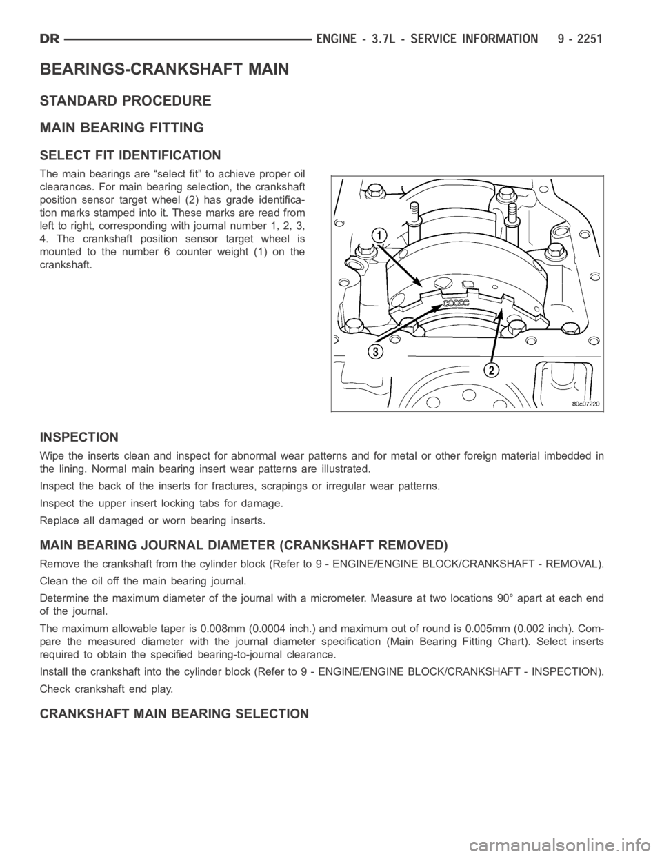
SELECT FIT IDENTIFICATION
The main bearings are “select fit” to achieve proper oil
clearances. For main bearing selection, the crankshaft
position sensor target wheel (2) has grade identifica-
tion marks stamped into it. These marks are read from
left to right, corresponding with journal number 1, 2, 3,
4. The crankshaft position sensor target wheel is
mounted to the number 6 counter weight (1) on the
crankshaft.
INSPECTION
Wipe the inserts clean and inspect for abnormal wear patterns and for metalor other foreign material imbedded in
the lining. Normal main bearing insert wear patterns are illustrated.
Inspect the back of the inserts for fractures, scrapings or irregular wearpatterns.
Inspect the upper insert locking tabs for damage.
Replace all damaged or worn bearing inserts.
MAIN BEARING JOURNAL DIAMETER (CRANKSHAFT REMOVED)
Remove the crankshaft from the cylinder block (Refer to 9 - ENGINE/ENGINE BLOCK/CRANKSHAFT - REMOVAL).
Clean the oil off the main bearing journal.
Determine the maximum diameter of the journal with a micrometer. Measure at two locations 90° apart at each end
of the journal.
The maximum allowable taper is 0.008mm (0.0004 inch.) and maximum out of round is 0.005mm (0.002 inch). Com-
pare the measured diameter with the journal diameter specification (MainBearing Fitting Chart). Select inserts
required to obtain the specified bearing-to-journal clearance.
Install the crankshaft into the cylinder block (Refer to 9 - ENGINE/ENGINEBLOCK/CRANKSHAFT - INSPECTION).
Check crankshaft end play.
CRANKSHAFT MAIN BEARING SELECTION
Page 1641 of 5267
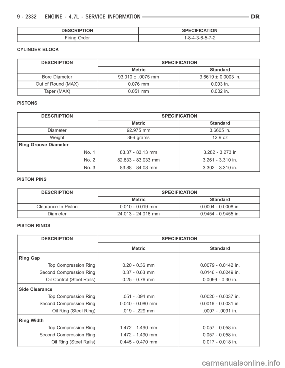
DESCRIPTION SPECIFICATION
Firing Order 1-8-4-3-6-5-7-2
CYLINDER BLOCK
DESCRIPTION SPECIFICATION
Metric Standard
Bore Diameter 93.010 ± .0075 mm 3.6619 ± 0.0003 in.
Out of Round (MAX) 0.076 mm 0.003 in.
Taper (MAX) 0.051 mm 0.002 in.
PISTONS
DESCRIPTION SPECIFICATION
Metric Standard
Diameter 92.975 mm 3.6605 in.
Weight 366 grams 12.9 oz
Ring Groove Diameter
No. 1 83.37 - 83.13 mm 3.282 - 3.273 in
No. 2 82.833 - 83.033 mm 3.261 - 3.310 in.
No. 3 83.88 - 84.08 mm 3.302 - 3.310 in.
PISTON PINS
DESCRIPTION SPECIFICATION
Metric Standard
Clearance In Piston 0.010 - 0.019 mm 0.0004 - 0.0008 in.
Diameter 24.013 - 24.016 mm 0.9454 - 0.9455 in.
PISTON RINGS
DESCRIPTION SPECIFICATION
Metric Standard
Ring Gap
Top Compression Ring 0.20 - 0.36 mm 0.0079 - 0.0142 in.
Second Compression Ring 0.37 - 0.63 mm 0.0146 - 0.0249 in.
Oil Control (Steel Rails) 0.25 - 0.76 mm 0.0099 - 0.30 in.
Side Clearance
Top Compression Ring .051 - .094 mm 0.0020 - 0.0037 in.
Second Compression Ring 0.040 - 0.080 mm 0.0016 - 0.0031 in.
Oil Ring (Steel Ring) .019 - .229 mm .0007 - .0091 in.
Ring Width
Top Compression Ring 1.472 - 1.490 mm 0.057 - 0.058 in.
Second Compression Ring 1.472 - 1.490 mm 0.057 - 0.058 in.
Oil Ring (Steel Rails) 0.445 - 0.470 mm 0.017 - 0.018 in.
Page 1642 of 5267
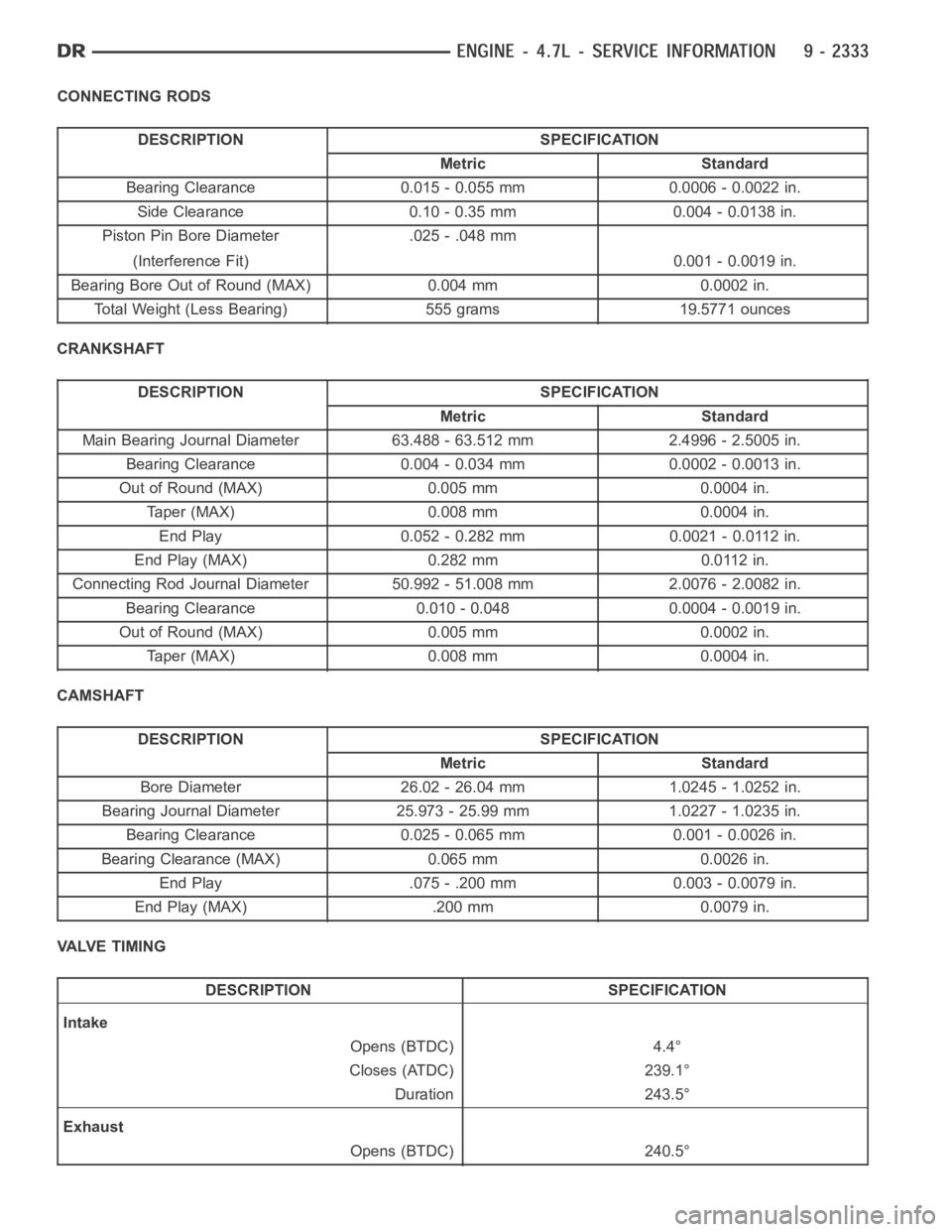
CONNECTING RODS
DESCRIPTION SPECIFICATION
Metric Standard
Bearing Clearance 0.015 - 0.055 mm 0.0006 - 0.0022 in.
Side Clearance 0.10 - 0.35 mm 0.004 - 0.0138 in.
Piston Pin Bore Diameter .025 - .048 mm
(Interference Fit) 0.001 - 0.0019 in.
Bearing Bore Out of Round (MAX) 0.004 mm 0.0002 in.
Total Weight (Less Bearing) 555 grams 19.5771 ounces
CRANKSHAFT
DESCRIPTION SPECIFICATION
Metric Standard
Main Bearing Journal Diameter 63.488 - 63.512 mm 2.4996 - 2.5005 in.
Bearing Clearance 0.004 - 0.034 mm 0.0002 - 0.0013 in.
Out of Round (MAX) 0.005 mm 0.0004 in.
Taper (MAX) 0.008 mm 0.0004 in.
End Play 0.052 - 0.282 mm 0.0021 - 0.0112 in.
End Play (MAX) 0.282 mm 0.0112 in.
Connecting Rod Journal Diameter 50.992 - 51.008 mm 2.0076 - 2.0082 in.
Bearing Clearance 0.010 - 0.048 0.0004 - 0.0019 in.
Out of Round (MAX) 0.005 mm 0.0002 in.
Taper (MAX) 0.008 mm 0.0004 in.
CAMSHAFT
DESCRIPTION SPECIFICATION
Metric Standard
Bore Diameter 26.02 - 26.04 mm 1.0245 - 1.0252 in.
Bearing Journal Diameter 25.973 - 25.99 mm 1.0227 - 1.0235 in.
Bearing Clearance 0.025 - 0.065 mm 0.001 - 0.0026 in.
BearingClearance(MAX) 0.065mm 0.0026in.
End Play .075 - .200 mm 0.003 - 0.0079 in.
End Play (MAX) .200 mm 0.0079 in.
VALVE TIMING
DESCRIPTION SPECIFICATION
Intake
Opens (BTDC) 4.4°
Closes (ATDC) 239.1°
Duration 243.5°
Exhaust
Opens (BTDC) 240.5°
Page 1694 of 5267
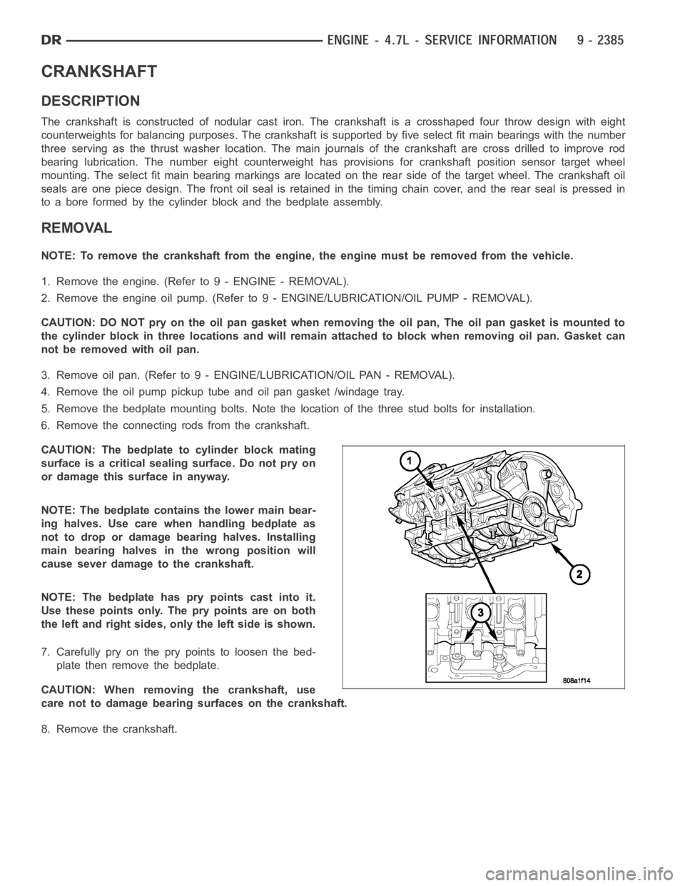
CRANKSHAFT
DESCRIPTION
The crankshaft is constructed of nodular cast iron. The crankshaft is a crosshaped four throw design with eight
counterweights for balancing purposes. The crankshaft is supported by five select fit main bearings with the number
three serving as the thrust washer location. The main journals of the crankshaft are cross drilled to improve rod
bearing lubrication. The number eight counterweight has provisions for crankshaft position sensor target wheel
mounting. The select fit main bearing markings are located on the rear sideof the target wheel. The crankshaft oil
seals are one piece design. The front oil seal is retained in the timing chain cover, and the rear seal is pressed in
to a bore formed by the cylinder block and the bedplate assembly.
REMOVAL
NOTE: To remove the crankshaft from the engine, the engine must be removed from the vehicle.
1. Remove the engine. (Refer to 9 - ENGINE - REMOVAL).
2. Remove the engine oil pump. (Refer to 9 - ENGINE/LUBRICATION/OIL PUMP - REMOVAL).
CAUTION: DO NOT pry on the oil pan gasket when removing the oil pan, The oil pan gasket is mounted to
the cylinder block in three locations and will remain attached to block when removing oil pan. Gasket can
not be removed with oil pan.
3. Remove oil pan. (Refer to 9 - ENGINE/LUBRICATION/OIL PAN - REMOVAL).
4. Remove the oil pump pickup tube and oil pan gasket /windage tray.
5. Remove the bedplate mounting bolts. Note the location of the three stud bolts for installation.
6. Remove the connecting rods from the crankshaft.
CAUTION: The bedplate to cylinder block mating
surface is a critical sealing surface. Do not pry on
or damage this surface in anyway.
NOTE: The bedplate contains the lower main bear-
ing halves. Use care when handling bedplate as
not to drop or damage bearing halves. Installing
main bearing halves in the wrong position will
cause sever damage to the crankshaft.
NOTE: The bedplate has pry points cast into it.
Use these points only. The pry points are on both
the left and right sides, only the left side is shown.
7. Carefully pry on the pry points to loosen the bed-
plate then remove the bedplate.
CAUTION: When removing the crankshaft, use
care not to damage bearing surfaces on the crankshaft.
8. Remove the crankshaft.
Page 1698 of 5267
BEARINGS - CRANKSHAFT MAIN
STANDARD PROCEDURE - CRANKSHAFT MAIN BEARING - FITTING
MAIN BEARING JOURNAL DIAMETER (CRANKSHAFT REMOVED)
Crankshaft removed from the cylinder block.
Clean the oil off the main bearing journal.
Determine the maximum diameter of the journal with a micrometer. Measure at two locations 90° apart at each end
of the journal.
The maximum allowable taper is 0.008mm (0.0004 inch.) and maximum out of round is 0.005mm (0.002 inch). Com-
pare the measured diameter with the journal diameter specification (MainBearing Fitting Chart). Select inserts
required to obtain the specified bearing-to-journal clearance.
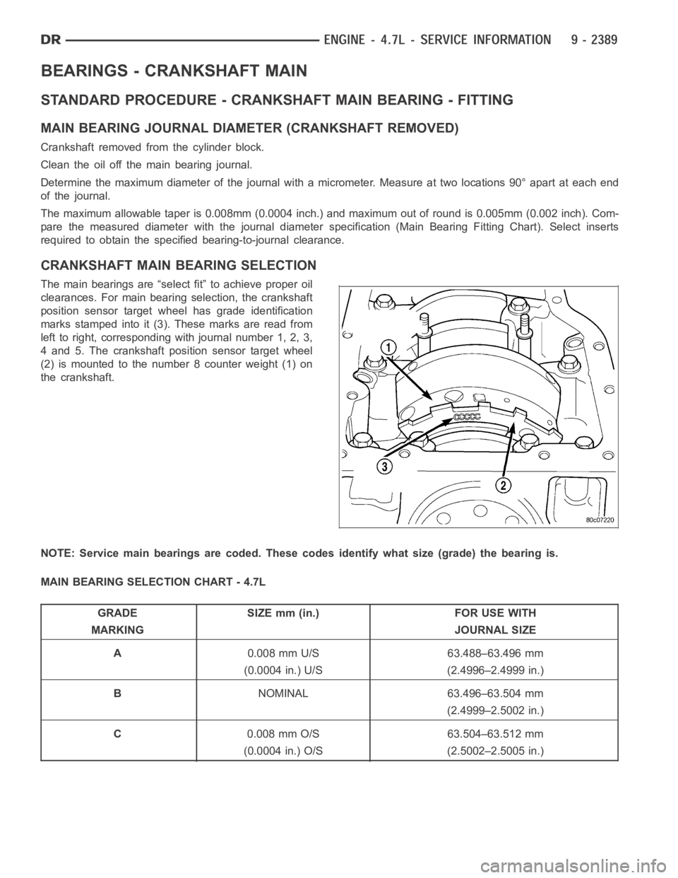
CRANKSHAFT MAIN BEARING SELECTION
The main bearings are “select fit” to achieve proper oil
clearances. For main bearing selection, the crankshaft
position sensor target wheel has grade identification
marks stamped into it (3). These marks are read from
left to right, corresponding with journal number 1, 2, 3,
4 and 5. The crankshaft position sensor target wheel
(2) is mounted to the number 8 counter weight (1) on
the crankshaft.
NOTE: Service main bearings are coded. These codes identify what size (grade) the bearing is.
MAIN BEARING SELECTION CHART - 4.7L
GRADE SIZE mm (in.) FOR USE WITH
MARKING JOURNAL SIZE
A0.008 mm U/S 63.488–63.496 mm
(0.0004 in.) U/S (2.4996–2.4999 in.)
BNOMINAL 63.496–63.504 mm
(2.4999–2.5002 in.)
C0.008 mm O/S 63.504–63.512 mm
(0.0004 in.) O/S (2.5002–2.5005 in.)
Page 1758 of 5267
ENGINE - 5.7L - SERVICE INFORMATION
DESCRIPTION
The 5.7L engine (345 CID) eight-cylinder engine is a 90° V-Type lightweight, deep skirt cast iron block, aluminum
heads, single cam, overhead valve engine with hydraulic roller tappets. The heads incorporate splayed valves with
a hemispherical style combustion chamber and dual spark plugs. The cylinders are numbered from front to rear; 1,
3, 5, 7 on the left bank and 2, 4, 6, 8 on the right bank. The firing order is 1-8-4-3-6-5-7-2.
DIAGNOSIS AND TESTING
DIAGNOSIS AND TESTING - ENGINE DIAGNOSIS - INTRODUCTION
Engine diagnosis is helpful in determining the causes of malfunctions notdetected and remedied by routine main-
tenance.
These malfunctions may be classified as either performance (e.g., engineidles rough and stalls) or mechanical
(e.g., a strange noise).
(Refer to 9 - ENGINE - DIAGNOSIS AND TESTING) - PERFORMANCE and (Refer to 9 - ENGINE - DIAGNOSIS
AND TESTING)—MECHANICAL for possible causes and corrections of malfunctions. (Refer to 14 - FUEL SYSTEM/
FUEL DELIVERY - DIAGNOSIS AND TESTING) and (Refer to 14 - FUEL SYSTEM/FUEL INJECTION - DIAGNO-
SIS AND TESTING) for the fuel system diagnosis.
Additional tests and diagnostic procedures may be necessary for specificengine malfunctions that can not be iso-
lated with the Service Diagnosis charts. Information concerning additional tests and diagnosis is provided within the
following diagnosis:
Cylinder Compression Pressure Test (Refer to 9 - ENGINE - DIAGNOSIS AND TESTING).
Cylinder Combustion Pressure LeakageTest (Refer to 9 - ENGINE - DIAGNOSISAND TESTING).
Engine Cylinder Head Gasket Failure Diagnosis (Refer to 9 - ENGINE/CYLINDER HEAD - DIAGNOSIS AND
TESTING).
Intake Manifold Leakage Diagnosis (Refer to 9 - ENGINE/MANIFOLDS/INTAKEMANIFOLD - DIAGNOSIS
AND TESTING).
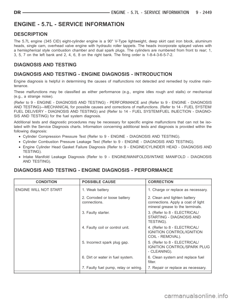
DIAGNOSIS AND TESTING - ENGINE DIAGNOSIS - PERFORMANCE
CONDITION POSSIBLE CAUSE CORRECTION
ENGINE WILL NOT START 1. Weak battery 1. Charge or replace as necessary.
2. Corroded or loose battery
connections.2. Clean and tighten battery
connections. Apply a coat of light
mineral grease to the terminals.
3. Faulty starter. 3. (Refer to 8 - ELECTRICAL/
STARTING - DIAGNOSIS AND
TESTING).
4. Faulty coil or control unit. 4. (Refer to 8 - ELECTRICAL/
IGNITION CONTROL/IGNITION
COIL - REMOVAL).
5. Incorrect spark plug gap. 5. (Refer to 8 - ELECTRICAL/
IGNITION CONTROL/SPARK PLUG
- CLEANING).
6. Dirt or water in fuel system. 6. Clean system and replace fuel
filter.
7. Faulty fuel pump, relay or wiring. 7. Repair or replace as necessary.