2006 DODGE RAM SRT-10 tire size
[x] Cancel search: tire sizePage 1273 of 5267
3.VISUAL AND PHYSICAL INSPECTION
Perform a visual and physical inspection of the entire Evaporative Emission system.
Check for the follow conditions:
- Holes or cracks
- Loose seal points
- Evidence of damaged components
- Incorrect routing of hoses and tubes
- Fuel Cap gasket seal
Were any of the above conditions found?
Ye s>>
Repair as necessary.
Perform the POWERTRAIN VERIFICATION TEST. (Refer to 9 - ENGINE - STANDARD PROCEDURE)
No>>
Go To 4
4.VERIFY EVAPORATIVE EMISSION LEAK
To continue testing you will need Miller Tool #8404A Evaporative EmissionLeak Detector (EELD).
WARNING: Keep lit cigarettes, sparks, flames, and other ignition sourcesaway from the test area to prevent
the ignition of explosive gases. Keep the test area well ventilated.
NOTE: The fuel tank should have between 20% and 80% of fuel tank capacity to properly test the Evap
system.
Connect the red power lead of the EELD to the battery positive terminal and the black ground lead to battery neg-
ative terminal.
Block the vent hose of the canister if using the service port.
Connect shop air to the EELD.
Set the smoke/air control switch to AIR.
Insert the tester’s AIR supply tip (clear hose) into the appropriate calibration orifice on the tester’s control panel
(based on DTC leak size).
Press the remote smoke/air start button.
Position the red flag on the air flow meter so it is aligned with the indicatorball.
When the calibration is complete, release the remote button. The EELD flowmeter is now calibrated in liters per
minute to the size leak indicated by the DTC set in the PCM.
Install the service port adapter #8404-14 on the vehicle’s service port and block the vent hose of the EVAP Canister
(if equipped) or install the #8404-ADP service adaptor into the filter line.
Connect the Air supply hose from the EELD to the service port (if equipped) or to the #8404-ADP adapter.
Press the remote button to activate AIR flow.
NOTE: Larger volume fuel tanks, lower fuel levels or if the vehicle is equipped with a Flow Management
Valve may indicate high flow and will require 4 to 5 minutes to fill.
Compare the flow meter indicator ball reading to the red flag.
ABOVE the red flag indicates a leak present.
BELOW the red flag indicates a sealed system.
Is the indicator ball above the red flag?
Ye s>>
Go To 5
No>>
Refer to the Freeze Frame data recorded in Step 1. If the data indicates thatthe vehicle was in motion
when the DTC was set, verify that all hoses are properly connected. Test Complete.
Page 1283 of 5267
3.VISUAL AND PHYSICAL INSPECTION
Perform a visual and physical inspection of the entire Evaporative Emission system.
Check for the follow conditions:
- Holes or cracks
- Loose seal points
- Evidence of damaged components
- Incorrect routing of hoses and tubes
- Fuel Cap gasket seal
Were any of the above conditions found?
Ye s>>
Repair as necessary.
Perform the POWERTRAIN VERIFICATION TEST. (Refer to 9 - ENGINE - STANDARD PROCEDURE)
No>>
Go To 4
4.VERIFY EVAPORATIVE EMISSION LEAK
To continue testing you will need Miller Tool #8404A Evaporative EmissionLeak Detector (EELD).
WARNING: Keep lit cigarettes, sparks, flames, and other ignition sourcesaway from the test area to prevent
the ignition of explosive gases. Keep the test area well ventilated.
NOTE: The fuel tank should have between 20% and 80% of fuel tank capacity to properly test the Evap
system.
Connect the red power lead of the EELD to the battery positive terminal and the black ground lead to battery neg-
ative terminal.
Block the vent hose of the canister if using the service port.
Connect shop air to the EELD.
Set the smoke/air control switch to AIR.
Insert the tester’s AIR supply tip (clear hose) into the appropriate calibration orifice on the tester’s control panel
(based on DTC leak size).
Press the remote smoke/air start button.
Position the red flag on the air flow meter so it is aligned with the indicatorball.
When the calibration is complete, release the remote button. The EELD flowmeter is now calibrated in liters per
minute to the size leak indicated by the DTC set in the PCM.
Install the service port adapter #8404-14 on the vehicle’s service port and block the vent hose of the EVAP Canister
(if equipped) or install the #8404-ADP service adaptor into the filter line.
Connect the Air supply hose from the EELD to the service port (if equipped) or to the #8404-ADP adapter.
Press the remote button to activate AIR flow.
NOTE: Larger volume fuel tanks, lower fuel levels or if the vehicle is equipped with a Flow Management
Valve may indicate high flow and will require 4 to 5 minutes to fill.
Compare the flow meter indicator ball reading to the red flag.
ABOVE the red flag indicates a leak present.
BELOW the red flag indicates a sealed system.
Is the indicator ball above the red flag?
Ye s>>
Go To 5
No>>
Refer to the INTERMITTENT CONDITION Diagnostic Procedure.
Perform the POWERTRAIN VERIFICATION TEST. (Refer to 9 - ENGINE - STANDARD PROCEDURE)
Page 1569 of 5267
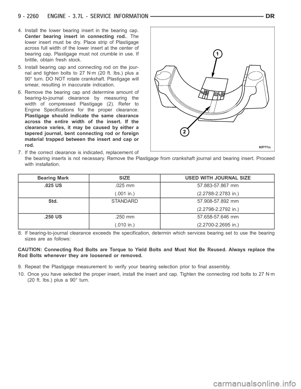
4. Install the lower bearing insert in the bearing cap.
Center bearing insert in connecting rod..The
lower insert must be dry. Place strip of Plastigage
across full width of the lower insert at the center of
bearing cap. Plastigage must not crumble in use. If
brittle, obtain fresh stock.
5. Install bearing cap and connecting rod on the jour-
nal and tighten bolts to 27 Nꞏm (20 ft. lbs.) plus a
90° turn. DO NOT rotate crankshaft. Plastigage will
smear, resulting in inaccurate indication.
6. Remove the bearing cap and determine amount of
bearing-to-journal clearance by measuring the
width of compressed Plastigage (2). Refer to
Engine Specifications for the proper clearance.
Plastigage should indicate the same clearance
across the entire width of the insert. If the
clearancevaries,itmaybecausedbyeithera
tapered journal, bent connecting rod or foreign
material trapped between the insert and cap or
rod.
7. If the correct clearance is indicated, replacement of
the bearing inserts is not necessary. Remove the Plastigage from crankshaft journal and bearing insert. Proceed
with installation.
Bearing Mark SIZE USED WITH JOURNAL SIZE
.025 US.025 mm 57.883-57.867 mm
(.001 in.) (2.2788-2.2783 in.)
Std.STANDARD 57.908-57.892 mm
(2.2798-2.2792 in.)
.250 US.250 mm 57.658-57.646 mm
(.010 in.) (2.2700-2.2695 in.)
8. If bearing-to-journal clearance exceeds the specification, determinwhich services bearing set to use the bearing
sizes are as follows:
CAUTION: Connecting Rod Bolts are Torque to Yield Bolts and Must Not Be Reused. Always replace the
Rod Bolts whenever they are loosened or removed.
9. Repeat the Plastigage measurement to verify your bearing selection prior to final assembly.
10. Once you have selected the proper insert, install the insert and cap. Tighten the connecting rod bolts to 27 Nꞏm
(20 ft. lbs.) plus a 90° turn.
Page 1692 of 5267
5. Install bearing cap and connecting rod on the jour-
nal and tighten bolts to 27 Nꞏm (20 ft. lbs.) plus a
90° turn. DO NOT rotate crankshaft. Plastigage will
smear, resulting in inaccurate indication.
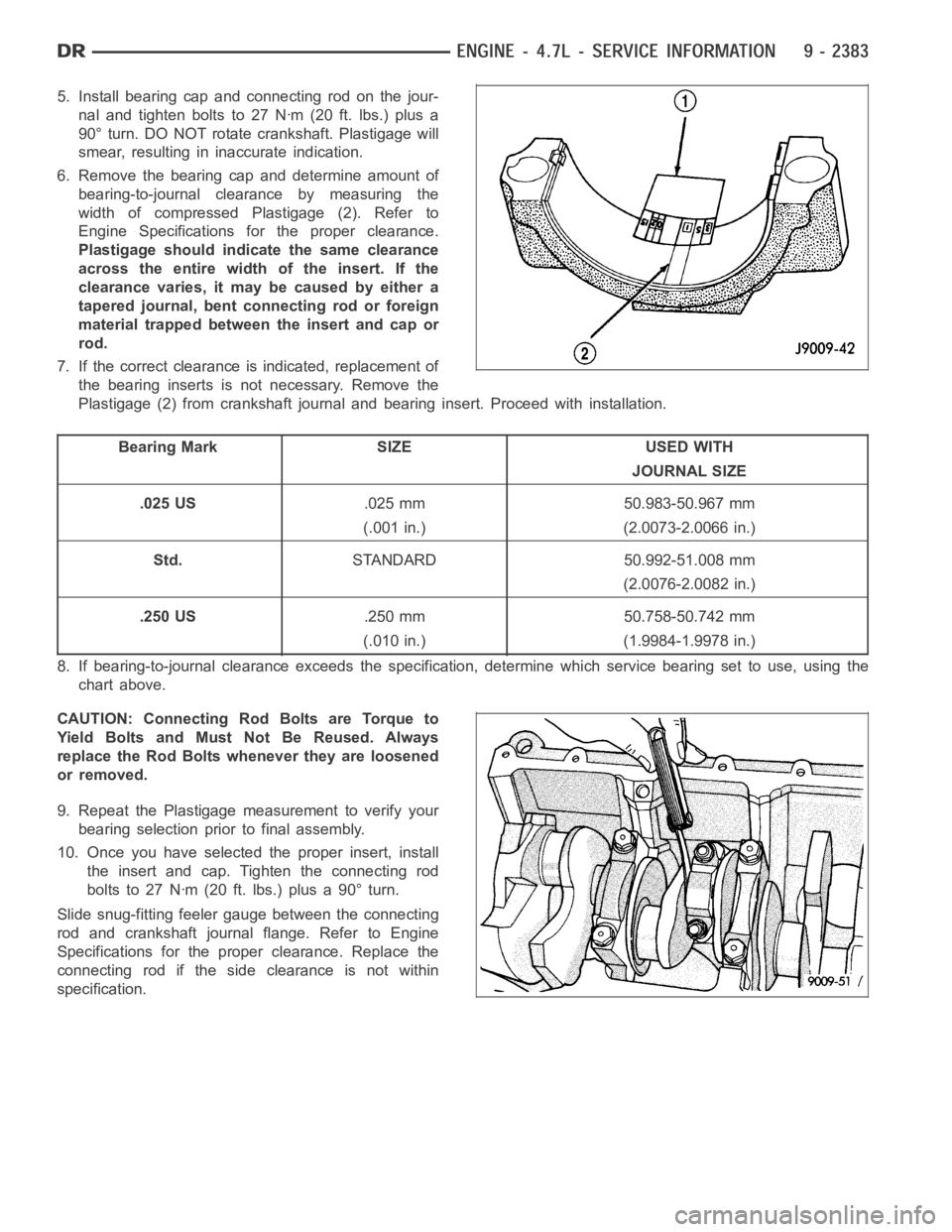
6. Remove the bearing cap and determine amount of
bearing-to-journal clearance by measuring the
width of compressed Plastigage (2). Refer to
Engine Specifications for the proper clearance.
Plastigage should indicate the same clearance
across the entire width of the insert. If the
clearancevaries,itmaybecausedbyeithera
tapered journal, bent connecting rod or foreign
material trapped between the insert and cap or
rod.
7. If the correct clearance is indicated, replacement of
the bearing inserts is not necessary. Remove the
Plastigage (2) from crankshaft journal and bearing insert. Proceed with installation.
Bearing Mark SIZE USED WITH
JOURNAL SIZE
.025 US.025 mm 50.983-50.967 mm
(.001 in.) (2.0073-2.0066 in.)
Std.STANDARD 50.992-51.008 mm
(2.0076-2.0082 in.)
.250 US.250 mm 50.758-50.742 mm
(.010 in.) (1.9984-1.9978 in.)
8. If bearing-to-journal clearance exceeds the specification, determine which service bearing set to use, using the
chart above.
CAUTION: Connecting Rod Bolts are Torque to
Yield Bolts and Must Not Be Reused. Always
replace the Rod Bolts whenever they are loosened
or removed.
9. Repeat the Plastigage measurement to verify your
bearing selection prior to final assembly.
10. Once you have selected the proper insert, install
the insert and cap. Tighten the connecting rod
bolts to 27 Nꞏm (20 ft. lbs.) plus a 90° turn.
Slide snug-fitting feeler gauge between the connecting
rod and crankshaft journal flange. Refer to Engine
Specifications for the proper clearance. Replace the
connecting rod if the side clearance is not within
specification.
Page 2119 of 5267
BEARINGS-CONNECTING ROD
DESCRIPTION
The bearing caps are not interchangeable and should be paint marked or scribed at removal to insure correct
assembly.
The bearing shells must be installed so that the tangs are in the machined grooves in the rods and caps.
Limits of taper or out-of-round on any crankshaft journals should be held to 0.013 mm (0.0005 in.). Bearings are
available in 0.025 mm (0.001 in.), 0.051 mm (0.002 in.), 0.076 mm (0.003 in.), 0.254 mm (0.010 in.) and 0.305 mm
(0.012 in.) undersize.Install the bearings in pairs. Do not use a new bearing half with an old bearing half. Do
not file the rods or bearing caps.
STANDARD PROCEDURE
CONNECTING ROD BEARING - FITTING
Fit all rods on one bank until complete. Do not alternate from one bank to another, because when the rods are
assembled to pistons correctly, they are not interchangeable from one bank to another.
The bearing caps are not interchangeable and should be marked at removal toinsure correct assembly.
The bearing shells must be installed so that the tangs are in the machined grooves in the rods and caps.
Limits of taper or out-of-round on any crankshaft journals should be held to 0.013 mm (0.0005 in.). Bearings are
available in 0.025 mm (0.001 in.), 0.051 mm (0.002 in.), 0.076 mm (0.003 in.), 0.254 mm (0.010 in.) and 0.305 mm
(0.012 in.) undersize.Install the bearings in pairs. Do not use a new bearing half with an old bearing half. Do
not file the rods or bearing caps.
1. (Refer to 9 - ENGINE/ENGINE BLOCK/CONNECTING ROD BEARINGS - STANDARD PROCEDURE) - Mea-
suring Connecting Rod Bearing Clearance to determine bearing clearance.
2. Before installing the connecting rod cap bolts, the bolt threads shouldbe oiled with engine oil.
3. Install bolts finger tight, then alternately torque each bolt to assemble the cap properly.
4. Tighten the connecting rod bolts to 68 Nꞏm (50 ft. lbs.).
MEASURING CONNECTING ROD BEARING CLEARANCE
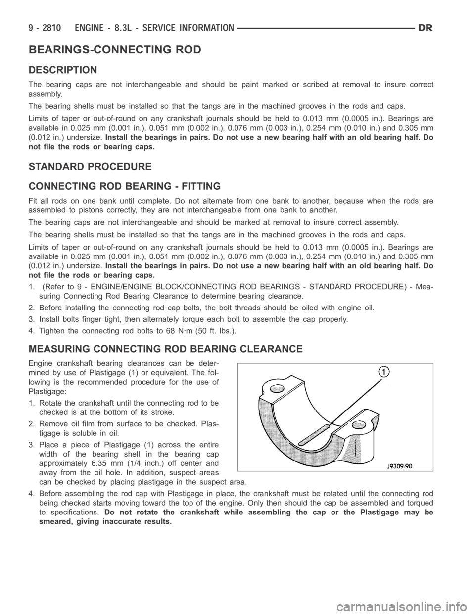
Engine crankshaft bearing clearances can be deter-
mined by use of Plastigage (1) or equivalent. The fol-
lowing is the recommended procedure for the use of
Plastigage:
1. Rotate the crankshaft until the connecting rod to be
checked is at the bottom of its stroke.
2. Remove oil film from surface to be checked. Plas-
tigage is soluble in oil.
3. Place a piece of Plastigage (1) across the entire
width of the bearing shell in the bearing cap
approximately 6.35 mm (1/4 inch.) off center and
away from the oil hole. In addition, suspect areas
can be checked by placing plastigage in the suspect area.
4. Before assembling the rod cap with Plastigage in place, the crankshaft must be rotated until the connecting rod
being checked starts moving toward the top of the engine. Only then should the cap be assembled and torqued
to specifications.Do not rotate the crankshaft while assembling the cap or the Plastigage maybe
smeared, giving inaccurate results.
Page 2343 of 5267
Fuel enters the system from the electric fuel transfer (lift) pump, which is located inside of the fuel tank and attached
to the fuel tank module (the fuel transfer pump is no longer attached to the engine). Fuel is forced through the fuel
filter element and then enters the Fuel Pump/Gear Pump, which is attached to the rear of the fuel injection pump.
The Fuel Pump/Gear Pump is a low-pressure pump and produce pressures ranging from 551.5 kpa (80 psi) to 1241
kpa (180) psi. Fuel then enters the fuel injection pump. Low pressure fuel is then supplied to the FCA (Fuel Control
Actuator).
The FCA is an electronically controlled solenoid valve. The ECM controls the amount of fuel that enters the high-
pressure pumping chambers by opening and closing the FCA based on a demanded fuel pressure. The FPS (Fuel
Pressure Sensor) on the fuel rail monitors the actual fuel pressure and provides it as an input to the ECM. When
the actuator is opened, the maximum amount of fuel is being supplied to the fuel injection pump. Any fuel that does
not enter the injection pump is directed to the overflow valve. The overflow valve regulates how much excess fuel
is used for lubrication of the pump and how much is returned to the tank through the drain manifold.
Fuel entering the injection pump is pressurized to between 300-1600 bar (4351-23,206 psi) by three radial pumping
chambers. The pressurized fuel is then supplied to the fuel rail.
STANDARD PROCEDURE
WATER DRAINING AT FUEL FILTER
Refer to Fuel Filter/Water Separatorremoval/installation for procedures.
CLEANING FUEL SYSTEM PARTS
CAUTION: Cleanliness cannot be overemphasized when handling or replacingdieselfuelsystemcompo-
nents. This especially includes the fuel injectors, high-pressure fuel lines and fuel injection pump. Very tight
tolerances are used with these parts. Dirt contamination could cause rapid part wear and possible plugging
of fuel injector nozzle tip holes. This in turn could lead to possible engine misfire. Always wash/clean any
fuel system component thoroughly before disassembly and then air dry. Capor cover any open part after
disassembly. Before assembly, examine each part for dirt, grease or othercontaminants and clean if nec-
essary. When installing new parts, lubricate them with clean engine oil orclean diesel fuel only.
FUEL SYSTEM PRIMING
A certain amount of air becomes trappedin the fuel system when fuel system components on the supply and/or
high-pressure side are serviced or replaced. Fuel system priming is accomplished using the electric fuel transfer (lift)
pump.
Servicing or replacing fuel system components will not require fuel systempriming.
The fuel transfer (lift) pump is self-priming: When the key is first turnedon (without cranking engine), the pump
operates for approximately 1 to 2 second and then shuts off (Note: When ambient temperatures are cold enough to
cause the intake air heaters to operate, the fuel lift pump will operate during the entire intake air pre-heat cycle).
The pump will also operate for up to 25 seconds after the starter is quickly engaged, and then disengaged without
allowing the engine to start. The pump shuts off immediately if the key is onand the engine stops running.
1. Turn key to CRANK position and quickly release key to ON position before engine starts. This will operate fuel
transfer pump for approximately 25 seconds.
2. Crank engine. If the engine does not start after 25 seconds, turn key to OFF position, and leave it off for at least
5 seconds. Repeat previous step until engine starts.
3. Fuel system priming is now completed.
4. Attempt to start engine. If engine will not start, proceed to following steps.When engine does start, it may run
erratically and be noisy for a few minutes. This is a normal condition.
CAUTION: Do not engage the starter motor for more than 30 seconds at a time. Allow two minutes between
cranking intervals.
5. Perform previous fuel priming procedure steps using fuel transfer pump. Be sure fuel is present at fuel tank.
6. Crank the engine for 30 seconds at a time to allow fuel system to prime.
Page 2408 of 5267
CONDITION POSSIBLE CAUSES CORRECTION
RATTLE OR CLUNK 1. Gear mounting bolts loose. 1. Tighten bolts to specification.
2. Loose or damaged suspension
components.2. Inspect and repair suspension.
3. Internal gear noise. 3. Replace steering gear.
4. Pressure hose in contact with other
components.4. Reposition hose.
5. Loose or damaged intermediate shaft or
column.5. Inspect and repair or replace.
CHIRP OR SQUEAL 1. Loose belt. 1. Adjust or replace.
WHINE OR GROWL 1. Low fluid level. 1. Fill to proper level.
2. Pressure hose in contact with other
components.2. Reposition hose.
3. Internal pump noise. 3. Replace pump.
4. Air in fluid 4. Check for leaks, Evacuate air
from P/S system.
SUCKING AIR SOUND 1. Loose return line clamp. 1. Replace clamp.
2. O-ring missing or damaged on hose
fitting.2. Replace o-ring.
3. Low fluid level. 3. Fill to proper level.
4. Air leak between pump and reservoir. 4. Repair as necessary.
5. Reservoir cap not installed correctly. 5. Install reservoir cap correctly.
SCRUBBING OR
KNOCKING1. Wrong tire size. 1. Verify tire size.
BINDING AND STICKING
CONDITION POSSIBLE CAUSE CORRECTION
DIFFICULT TO TURN WHEEL
STICKS OR BINDS1. Low fluid level. 1. Fill to proper level.
2. Tire pressure. 2. Adjust tire pressure.
3. Steering components (ball
joints/tie rod ends).3 Inspect and repair as necessary.
4. Loose belt. 4. Adjust or replace.
5. Low pump pressure. 5. Pressure test and replace if
necessary.
6. Column shaft coupler binding. 6. Replace coupler.
7. Steering gear worn. 7. Replace gear.
8. Pump seized / Stuck valve 8. Replace pump.
Page 3092 of 5267
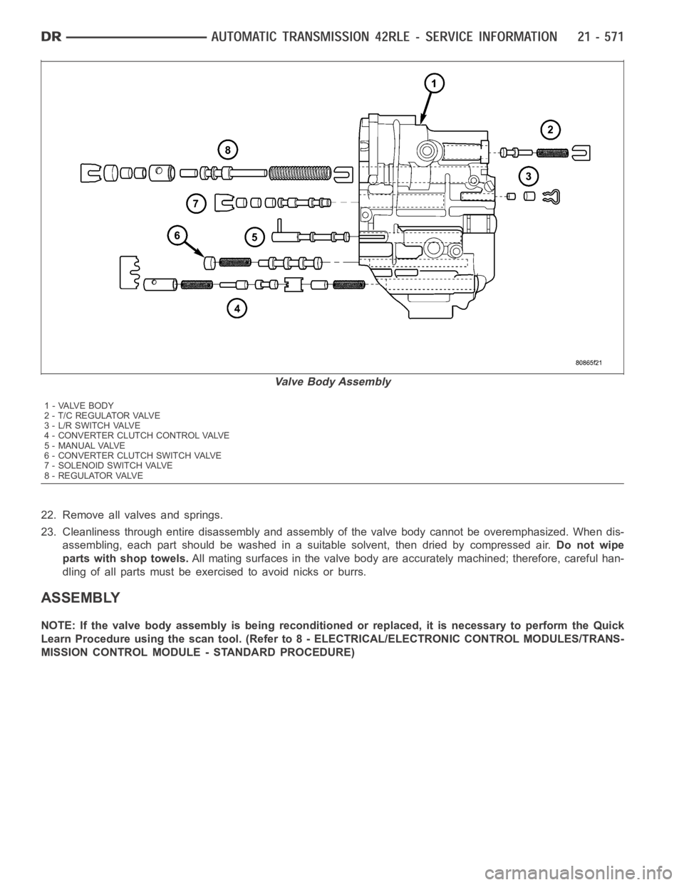
22. Remove all valves and springs.
23. Cleanliness through entire disassembly and assembly of the valve bodycannot be overemphasized. When dis-
assembling, each part should be washed in a suitable solvent, then dried bycompressed air.Do not wipe
parts with shop towels.All mating surfaces in the valve body are accurately machined; therefore,careful han-
dling of all parts must be exercised to avoid nicks or burrs.
ASSEMBLY
NOTE: If the valve body assembly is being reconditioned or replaced, it is necessary to perform the Quick
Learn Procedure using the scan tool. (Refer to 8 - ELECTRICAL/ELECTRONIC CONTROL MODULES/TRANS-
MISSION CONTROL MODULE - STANDARD PROCEDURE)
Valve Body Assembly
1-VALVEBODY
2 - T / C R E G U L AT O R VA LV E
3-L/RSWITCHVALVE
4 - CONVERTER CLUTCH CONTROL VALVE
5 - MANUAL VALVE
6 - CONVERTER CLUTCH SWITCH VALVE
7 - SOLENOID SWITCH VALVE
8 - REGULATOR VALVE