2006 DODGE RAM SRT-10 set clock
[x] Cancel search: set clockPage 726 of 5267

When Monitored:
While the ignition is on
Set Condition:
Speed control MUX switch below 1.0 volts for 5 seconds.
Possible Causes
S/C WIRING HARNESS OBSERVABLE PROBLEM
S/C SWITCH (ON/OFF)
CLOCKSPRING SHORTED TO GROUND
S/C SWITCH (RESUME/ACCEL)
S/C SWITCH SIGNAL CIRCUIT SHORTED TO GROUND
S/C SIGNAL CIRCUIT SHORTED TO SENSOR GROUND
ECM
Always perform the Pre-Diagnostic Troubleshooting procedure before proceeding. (Refer to 9 - ENGINE -
DIAGNOSIS AND TESTING)
Diagnostic Test
1.S/C SWITCH VOLTAGE BELOW 1.0 VOLT
Turn the ignition on.
With the scan tool, read the S/C Switch volts status in the ECM.
Is the S/C Switch voltage below 1.0 volt?
Ye s>>
Go To 3
No>>
Go To 2
2.S/C WIRING HARNESS OBSERVABLE PROBLEM
Turn the ignition off.
Using the Schematics as a guide, inspect the Wiring and Connectors.
Were any problems found?
Ye s>>
Repair as necessary.
Perform POWERTRAIN VERIFICATION TEST VER - 1 (DIESEL). (Refer to 8 - ELECTRICAL/ELEC-
TRONIC CONTROL MODULES/ENGINE CONTROL MODULE - DIAGNOSIS AND TESTING)
No>>
Go To 3
3.S/C SWITCH (ON/OFF)
Turn the ignition off.
Disconnect the S/C ON/OFF Switch harness connector.
NOTE: Check connectors - Clean/repair as necessary.
Turn the ignition on.
With the scan tool in Sensors, read the S/C Switch volts in the ECM.
Did the S/C Switch volts change to 5.0 volts?
Ye s>>
Replace the S/C ON/OFF Switch.
Perform POWERTRAIN VERIFICATION TEST VER - 1 (DIESEL). (Refer to 8 - ELECTRICAL/ELEC-
TRONIC CONTROL MODULES/ENGINE CONTROL MODULE - DIAGNOSIS AND TESTING)
No>>
Go To 4
Page 730 of 5267

When Monitored:
Key on or Engine running.
Set Condition:
Speed Control MUX switch above 11.5 volts for 5 seconds.
Possible Causes
S/C WIRING HARNESS OBSERVABLE PROBLEM
CLOCKSPRING SIGNAL/GROUND CIRCUIT OPEN
SPEED CONTROL ON/OFF SWITCH
S/C SWITCH SIGNAL CKT SHORTED TO VOLTAGE
S/C SWITCH SIGNAL CIRCUIT OPEN ECM TO CLOCK SPRING
S/C SWITCH SIGNAL CIRCUIT OPEN CLOCKSPRING TO S/C SWITCH
S/C SWITCH GROUND CIRCUIT OPEN CLOCKSPRING TO S/C SWITCH
S/C SWITCH GROUND CIRCUIT OPEN ECM TO CLOCKSPRING
ECM
Always perform the Pre-Diagnostic Troubleshooting procedure before proceeding. (Refer to 9 - ENGINE -
DIAGNOSIS AND TESTING)
Diagnostic Test
1.Scan tool SHOWS SPEED CONTROL SWITCH ON/OFF
Turn the ignition on.
With the scan tool in Inputs/Outputs, read the Speed Control inputs state inECM.
While monitoring the scan tool, push the Speed Control On/Off Switch several times, then leave it on.
Did the scan tool show Speed Control Switch off and on?
Ye s>>
Go To 2
No>>
Te s t C o m p l e t e .
2.S/C WIRING HARNESS OBSERVABLE PROBLEM
Turn the ignition off.
Using the Schematics as a guide, inspect the Wiring and Connectors.
Were any problems found?
Ye s>>
Repair as necessary.
Perform POWERTRAIN VERIFICATION TEST VER - 1 (DIESEL). (Refer to 8 - ELECTRICAL/ELEC-
TRONIC CONTROL MODULES/ENGINE CONTROL MODULE - DIAGNOSIS AND TESTING)
No>>
Go To 3
Page 897 of 5267
*INTAKE AIR SYSTEM PRESSURE TEST
Diagnostic Test
1.CHARGE AIR COOLER PRESSURE TEST
Loosen air inlet tube clamp at the turbocharger.
Remove the air filter housing and the inlet tube from the vehicle as an assembly.
Install the CAC Pressure Tester #9022 into the inner diameter of the turbocharger, securing it in place with the
supplied three-fingered band clamp, tighten tool clamp to 8n.m (72 in lbs).
NOTE: NEVER ATTEMPT TO START OR RUN THE VEHICLE AT ANY TIME DURING THIS TEST,ENGINE DAM-
AGE MAY OCCUR.
Fasten the safety chain around a solid surface behind the turbocharger. Warning: Never run CAC Pressure test
without the safety chain securely fastened.
Before attaching shop air to the pressure regulator verify that the regulator is at its lowest pressure setting (0 psi).
Attach an air supply to the regulator and slowly increase the pressure until the pressure gauge reads 20 psi.
WARNING: WARNING: Never apply more than 20 PSI.
Using a solution of soap and water spray the Turbocharger, Turbocharger wastegate, Charge Air Cooler Heat
Exchange and CAC Hoses while watching for leaks.
Before any attempt to repair the CAC system is made, its necessary to completely discharge the system. This can
be accomplished by turning the regulator knob counter-clockwise.
Allow for adequate time to pass before removing the CAC Pressure tester from the turbo charger inlet.
Position the Air Filter Housing over thethreemountingstudslocatedonthe inside front fender well and press down
firmly to lock housing into place.
Install Air Inlet Tube over the Turbocharger inlet and torque the band clampto35in.lbs.
View Repair
Repair
Te s t c o m p l e t e .
Perform POWERTRAIN VERIFICATION TEST VER - 1 (DIESEL). (Refer to 8 - ELECTRICAL/ELEC-
TRONIC CONTROL MODULES/ENGINE CONTROL MODULE - DIAGNOSIS AND TESTING)
Page 1518 of 5267
7. Remove the master cylinder and booster assembly (Refer to 5 - BRAKES/HYDRAULIC/MECHANICAL/POWER
BRAKE BOOSTER - REMOVAL).
8. Remove the cylinder head cover (Refer to 9 - ENGINE/CYLINDER HEAD/CYLINDER HEAD COVER(S) -
REMOVAL).
9. Remove the fan shroud and fan blade assembly
(Refer to 7 - COOLING/ENGINE/RADIATOR FAN -
REMOVAL).
10. Remove accessory drive belt (Refer to 7 - COOL-
ING/ACCESSORY DRIVE/DRIVE BELTS -
REMOVAL).
11. Remove the power steering pump and set aside.
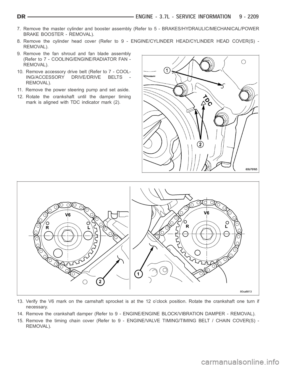
12. Rotate the crankshaft until the damper timing
mark is aligned with TDC indicator mark (2).
13. Verify the V6 mark on the camshaft sprocket is at the 12 o’clock position. Rotate the crankshaft one turn if
necessary.
14. Remove the crankshaft damper (Refer to 9 - ENGINE/ENGINE BLOCK/VIBRATION DAMPER - REMOVAL).
15. Remove the timing chain cover (Refer to 9 - ENGINE/VALVE TIMING/TIMINGBELT / CHAIN COVER(S) -
REMOVAL).
Page 1523 of 5267
CAMSHAFT
DESCRIPTION
The camshafts consist of powdered metal steel lobes which are sinter-bonded to a steel tube. Four bearing journals
are machined into the camshaft. Camshaft end play is controlled by two thrust walls that border the nose piece
journal.
REMOVAL
CAUTION: When the timing chain is removed and the cylinder heads are still installed, DO NOT forcefully
rotate the camshafts or crankshaft independently of each other. Severe valve and/or piston damage can
occur.
CAUTION: When removing the cam sprocket, timing chains or camshaft, Failure to use Special Tool 8379
will result in hydraulic tensioner ratchet over extension, requiring timing chain cover removal to reset the
tensioner ratchet.
1. Remove cylinder head cover (Refer to 9 - ENGINE/CYLINDER HEAD/CYLINDERHEAD COVER(S) -
REMOVAL).
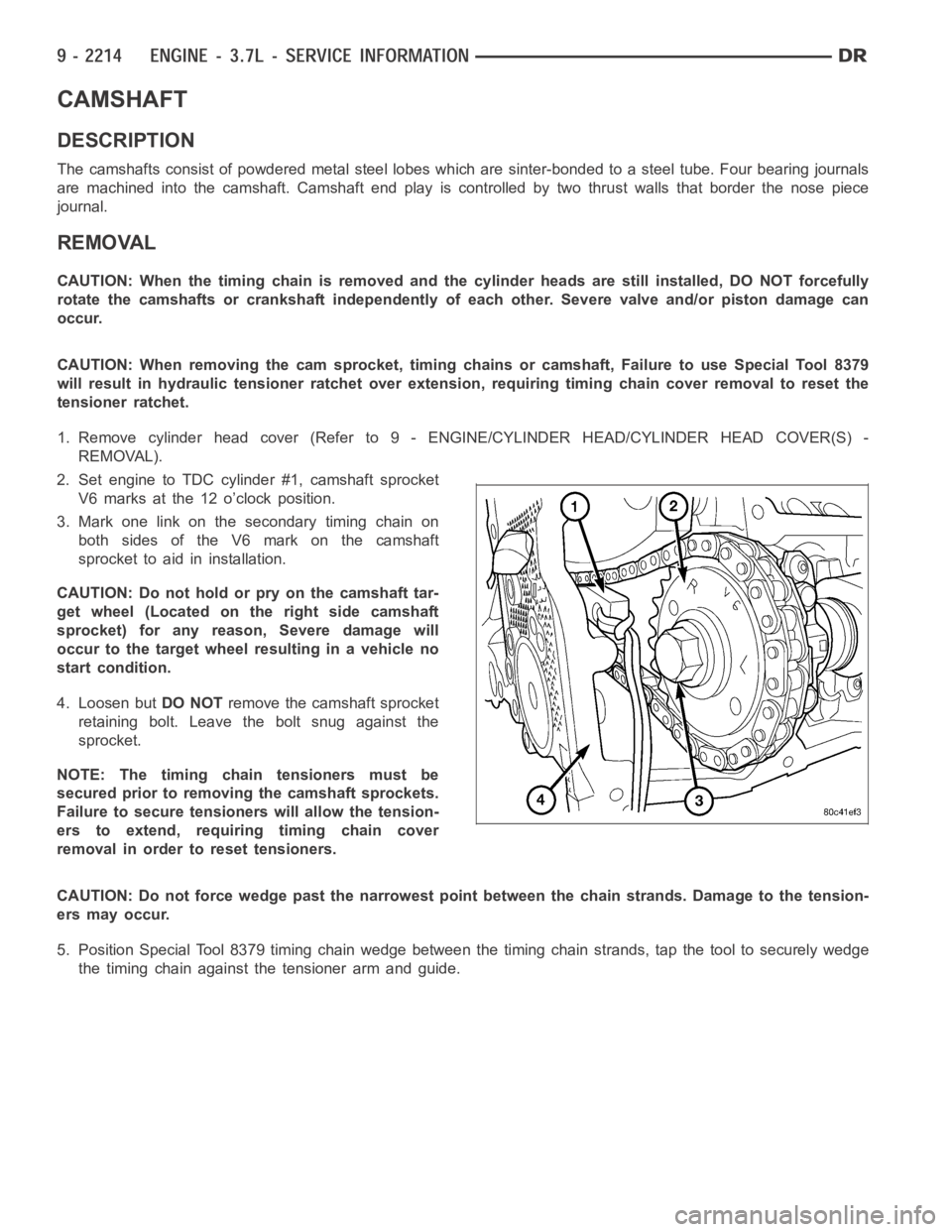
2. Set engine to TDC cylinder #1, camshaft sprocket
V6 marks at the 12 o’clock position.
3. Mark one link on the secondary timing chain on
both sides of the V6 mark on the camshaft
sprocket to aid in installation.
CAUTION: Do not hold or pry on the camshaft tar-
get wheel (Located on the right side camshaft
sprocket) for any reason, Severe damage will
occur to the target wheel resulting in a vehicle no
start condition.
4. Loosen butDO NOTremove the camshaft sprocket
retaining bolt. Leave the bolt snug against the
sprocket.
NOTE: The timing chain tensioners must be
secured prior to removing the camshaft sprockets.
Failure to secure tensioners will allow the tension-
erstoextend,requiringtimingchaincover
removal in order to reset tensioners.
CAUTION: Do not force wedge past the narrowest point between the chain strands. Damage to the tension-
ers may occur.
5. Position Special Tool 8379 timing chain wedge between the timing chain strands, tap the tool to securely wedge
the timing chain against the tensioner arm and guide.
Page 1543 of 5267
CAMSHAFT
DESCRIPTION
The camshafts consist of powdered metal steel lobes which are sinter-bonded to a steel tube. Four bearing journals
are machined into the camshaft. Camshaft end play is controlled by two thrust walls that border the nose piece
journal.
REMOVAL
CAUTION: When the timing chain is removed and the cylinder heads are still installed, DO NOT forcefully
rotate the camshafts or crankshaft independently of each other. Severe valve and/or piston damage can
occur.
CAUTION: When removing the cam sprocket, timing chains or camshaft, Failure to use special tool 8379 will
result in hydraulic tensioner ratchet over extension, Requiring timing chain cover removal to re-set the ten-
sioner ratchet.
1. Remove the cylinder head cover (Refer to 9 - ENGINE/CYLINDER HEAD/CYLINDER HEAD COVER(S) -
REMOVAL).
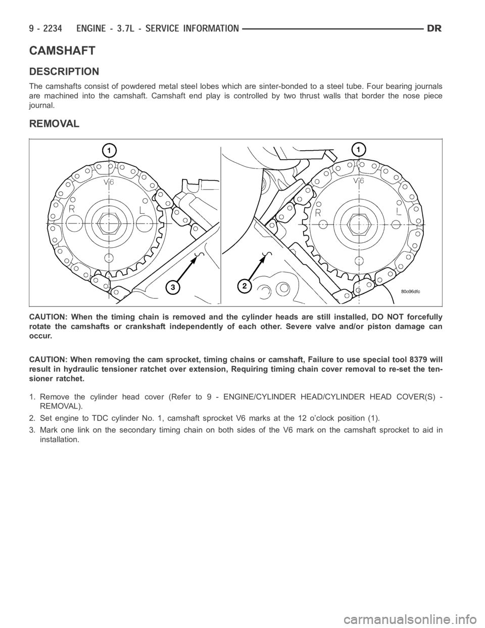
2. Set engine to TDC cylinder No. 1, camshaft sprocket V6 marks at the 12 o’clock position (1).
3. Mark one link on the secondary timing chain on both sides of the V6 mark on the camshaft sprocket to aid in
installation.
Page 1666 of 5267
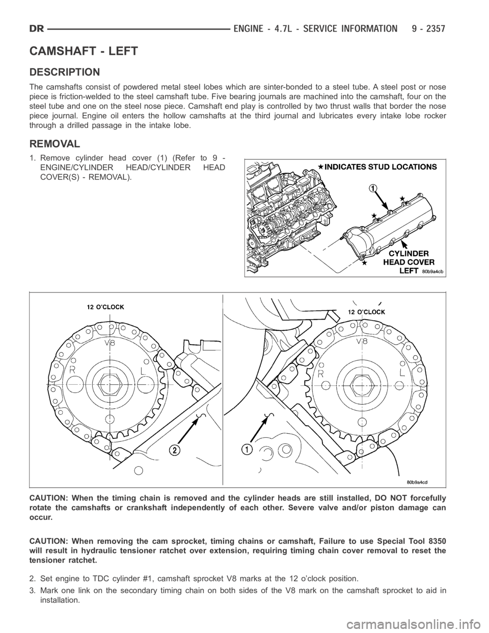
CAMSHAFT - LEFT
DESCRIPTION
The camshafts consist of powdered metal steel lobes which are sinter-bonded to a steel tube. A steel post or nose
piece is friction-welded to the steel camshaft tube. Five bearing journals are machined into the camshaft, four on the
steel tube and one on the steel nose piece. Camshaft end play is controlled by two thrust walls that border the nose
piece journal. Engine oil enters the hollow camshafts at the third journaland lubricates every intake lobe rocker
throughadrilledpassageintheintakelobe.
REMOVAL
1. Remove cylinder head cover (1) (Refer to 9 -
ENGINE/CYLINDER HEAD/CYLINDER HEAD
COVER(S) - REMOVAL).
CAUTION: When the timing chain is removed and the cylinder heads are still installed, DO NOT forcefully
rotate the camshafts or crankshaft independently of each other. Severe valve and/or piston damage can
occur.
CAUTION: When removing the cam sprocket, timing chains or camshaft, Failure to use Special Tool 8350
will result in hydraulic tensioner ratchet over extension, requiring timing chain cover removal to reset the
tensioner ratchet.
2. Set engine to TDC cylinder #1, camshaft sprocket V8 marks at the 12 o’clock position.
3. Mark one link on the secondary timing chain on both sides of the V8 mark on the camshaft sprocket to aid in
installation.
Page 1667 of 5267
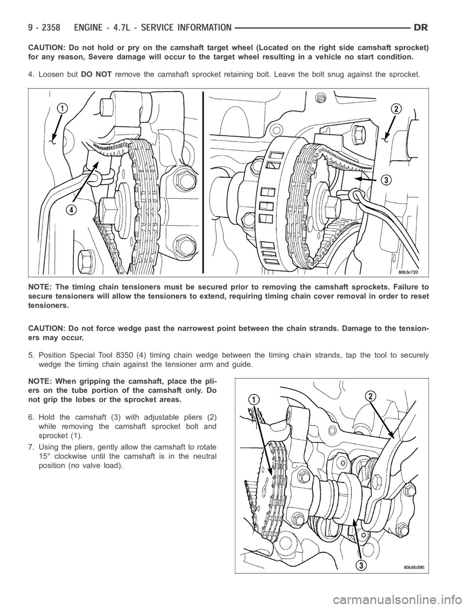
CAUTION: Do not hold or pry on the camshaft target wheel (Located on the right side camshaft sprocket)
for any reason, Severe damage will occur to the target wheel resulting in a vehicle no start condition.
4. Loosen butDO NOTremove the camshaft sprocket retaining bolt. Leave the bolt snug against the sprocket.
NOTE: The timing chain tensioners must be secured prior to removing the camshaft sprockets. Failure to
secure tensioners will allow the tensioners to extend, requiring timing chain cover removal in order to reset
tensioners.
CAUTION: Do not force wedge past the narrowest point between the chain strands. Damage to the tension-
ers may occur.
5. Position Special Tool 8350 (4) timing chain wedge between the timing chain strands, tap the tool to securely
wedge the timing chain against the tensioner arm and guide.
NOTE: When gripping the camshaft, place the pli-
ers on the tube portion of the camshaft only. Do
not grip the lobes or the sprocket areas.
6. Hold the camshaft (3) with adjustable pliers (2)
while removing the camshaft sprocket bolt and
sprocket (1).
7. Using the pliers, gently allow the camshaft to rotate
15° clockwise until the camshaft is in the neutral
position (no valve load).