Page 2200 of 5267

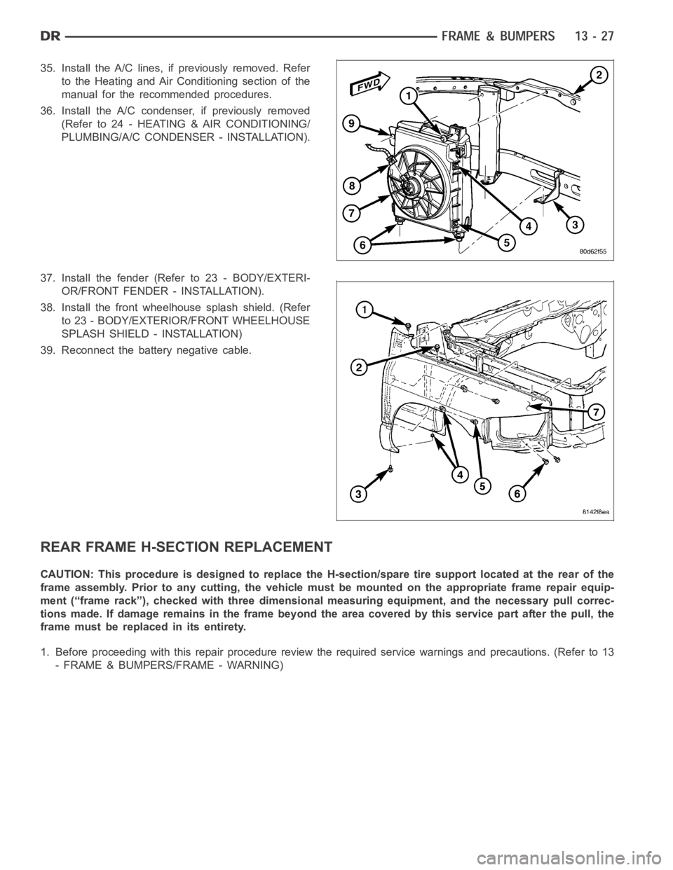
35. Install the A/C lines, if previously removed. Refer
to the Heating and Air Conditioning section of the
manual for the recommended procedures.
36. Install the A/C condenser, if previously removed
(Refer to 24 - HEATING & AIR CONDITIONING/
PLUMBING/A/C CONDENSER - INSTALLATION).
37. Install the fender (Refer to 23 - BODY/EXTERI-
OR/FRONT FENDER - INSTALLATION).
38. Install the front wheelhouse splash shield. (Refer
to 23 - BODY/EXTERIOR/FRONT WHEELHOUSE
SPLASH SHIELD - INSTALLATION)
39. Reconnect the battery negative cable.
REAR FRAME H-SECTION REPLACEMENT
CAUTION: This procedure is designed to replace the H-section/spare tire support located at the rear of the
frame assembly. Prior to any cutting, the vehicle must be mounted on the appropriate frame repair equip-
ment (“frame rack”), checked with three dimensional measuring equipment, and the necessary pull correc-
tions made. If damage remains in the frame beyond the area covered by this service part after the pull, the
frame must be replaced in its entirety.
1. Before proceeding with this repair procedure review the required service warnings and precautions. (Refer to 13
- FRAME & BUMPERS/FRAME - WARNING)
Page 2203 of 5267
7. Remove the rear leaf spring shackle bolts (6) and
let the axle rest on the ground.
8. Remove the spare wheel.
9.Removetheclip(2)andremovethesparetire
winch tube (3).
10. Remove the bolts (2) and remove the spare tire
winch (1).
11. Position the wire harness forward of the work
area.
Page 4314 of 5267

TIRES/WHEELS
TABLE OF CONTENTS
page page
TIRES/WHEELS
DIAGNOSIS AND TESTING
TIRE AND WHEEL RUNOUT .................. 2
STANDARD PROCEDURE
MATCH MOUNTING .......................... 4
TIRE AND WHEEL BALANCE ................. 5
TIRE ROTATION ............................. 6
SPECIFICATIONS
TORQUE .................................... 7
TIRES
DESCRIPTION
TIRES ....................................... 8
SPARE / TEMPORARY TIRE .................. 8
RADIAL – PLY TIRES ......................... 8
TIRE PRESSURE FOR HIGH SPEEDS......... 9
REPLACEMENT TIRES ....................... 9
TIRE INFLATION PRESSURES ................ 9
DIAGNOSIS AND TESTING
PRESSURE GAUGES ....................... 10
TIRE NOISE OR VIBRATION ................. 10
TREAD WEAR INDICATORS ................. 10
TIRE WEAR PATTERNS ..................... 11
TIRE/VEHICLE LEAD ........................ 12
STANDARD PROCEDURE
TIRE REPAIR AREA ......................... 13
CLEANING
TIRES ..................................... 13SPECIFICATIONS
TIRE REVOLUTIONS PER MILE .............. 13
WHEELS
DESCRIPTION
DESCRIPTION .............................. 15
WHEEL DESIGN ............................ 16
DIAGNOSIS AND TESTING
WHEEL INSPECTION....................... 16
STANDARD PROCEDURE
WHEEL REPLACEMENT ..................... 16
DUAL REAR WHEEL INSTALLATION .......... 18
STUDS
REMOVAL .................................... 20
INSTALLATION ............................... 20
WHEEL COVER
REMOVAL .................................... 22
INSTALLATION
REAR ...................................... 22
FRONT .................................... 22
SPARE TIRE
DESCRIPTION
SPARE / TEMPORARY TIRE ................. 23
FULL SIZE, SPARE WHEEL WITH
MATCHING TIRE............................ 23
Page 4320 of 5267
CAUTION: 3500 Dual rear tires have a new tire
rotation pattern. This is to accommodate the out-
lined white letter (OWL) tires. When replacing a
flat, the spare tire may have to be remounted on
the rim or installed at a different location to main-
tain the correct placement of the outlined white
letter (OWL) tires.
The recommended method of tire rotation for dual rear
wheel is. Other methods can be used, but may not
provide the same tire longevity benefits.
SPECIFICATIONS
TORQUE
DESCRIPTION Nꞏm Ft. Lbs. In. Lbs.
1500 Series
Lug Nut 9/16 X 18 with
60° Cone
LD176 130 —
2500 Series
Lug Nut 9/16 X 18 with
60° Cone
HD SRW190 140 —
3500 Series
Lug Nut 9/16 X 18 with
Flat Washer
HD DRW197 145 —
Page 4321 of 5267

TIRES
DESCRIPTION
TIRES
Tires are designed and engineered for each specific vehicle. They providethe best overall performance for normal
operation. The ride and handling characteristics match the vehicle’s requirements. With proper care they will give
excellent reliability, traction,skid resistance, and tread life.
Driving habits have more effect on tire life than any other factor. Carefuldrivers will obtain in most cases, much
greater mileage than severe use or careless drivers. A few of the driving habits which will shorten the life of any tire
are:
Rapid acceleration
Severe brake applications
High speed driving
Excessive speeds on turns
Striking curbs and other obstacles
Radial-ply tires are more prone to irregular tread wear. It is important tofollow the tire rotation interval (Refer to 22
- TIRES/WHEELS - STANDARD PROCEDURE). This will help to achieve a greater tread life.
TIRE IDENTIFICATION
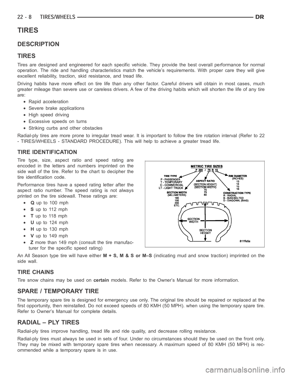
Tire type, size, aspect ratio and speed rating are
encoded in the letters and numbers imprinted on the
side wall of the tire. Refer to the chart to decipher the
tire identification code.
Performance tires have a speed rating letter after the
aspect ratio number. The speed rating is not always
printed on the tire sidewall. These ratings are:
Qup to 100 mph
Sup to 112 mph
Tup to 118 mph
Uup to 124 mph
Hup to 130 mph
Vup to 149 mph
Zmore than 149 mph (consult the tire manufac-
turer for the specific speed rating)
An All Season type tire will have eitherM+S,M&SorM–S(indicating mud and snow traction) imprinted on the
side wall.
TIRE CHAINS
Tire snow chains may be used oncertainmodels. Refer to the Owner’s Manual for more information.
SPARE / TEMPORARY TIRE
The temporary spare tire is designed for emergency use only. The original tire should be repaired or replaced at the
first opportunity, then reinstalled. Do not exceed speeds of 80 KMH (50 MPH). when using the temporary spare tire.
Refer to Owner’s Manual for complete details.
RADIAL – PLY TIRES
Radial-ply tires improve handling, tread life and ride quality, and decrease rolling resistance.
Radial-ply tires must always be used in sets of four. Under no circumstances should they be used on the front only.
They may be mixed with temporary spare tires when necessary. A maximum speedof80KMH(50MPH)isrec-
ommended while a temporary spare is in use.
Page 4336 of 5267
SPARE TIRE
DESCRIPTION
SPARE / TEMPORARY TIRE
The temporary spare tire is designed for emergency use only. The original tire should be repaired or replaced at the
first opportunity, then reinstalled. Do not exceed speeds of 80 KMH (50 MPH). when using the temporary spare tire.
Refer to Owner’s Manual for complete details.
FULL SIZE, SPARE WHEEL WITH MATCHING TIRE
The spare is a full usage wheel with a matching tire, It can be used within the(posted legal) speed limits or distance
limitations as of the rest of the vehicles four tires. Refer to Owner’s Manual for complete details.