2006 DODGE RAM SRT-10 clock
[x] Cancel search: clockPage 726 of 5267

When Monitored:
While the ignition is on
Set Condition:
Speed control MUX switch below 1.0 volts for 5 seconds.
Possible Causes
S/C WIRING HARNESS OBSERVABLE PROBLEM
S/C SWITCH (ON/OFF)
CLOCKSPRING SHORTED TO GROUND
S/C SWITCH (RESUME/ACCEL)
S/C SWITCH SIGNAL CIRCUIT SHORTED TO GROUND
S/C SIGNAL CIRCUIT SHORTED TO SENSOR GROUND
ECM
Always perform the Pre-Diagnostic Troubleshooting procedure before proceeding. (Refer to 9 - ENGINE -
DIAGNOSIS AND TESTING)
Diagnostic Test
1.S/C SWITCH VOLTAGE BELOW 1.0 VOLT
Turn the ignition on.
With the scan tool, read the S/C Switch volts status in the ECM.
Is the S/C Switch voltage below 1.0 volt?
Ye s>>
Go To 3
No>>
Go To 2
2.S/C WIRING HARNESS OBSERVABLE PROBLEM
Turn the ignition off.
Using the Schematics as a guide, inspect the Wiring and Connectors.
Were any problems found?
Ye s>>
Repair as necessary.
Perform POWERTRAIN VERIFICATION TEST VER - 1 (DIESEL). (Refer to 8 - ELECTRICAL/ELEC-
TRONIC CONTROL MODULES/ENGINE CONTROL MODULE - DIAGNOSIS AND TESTING)
No>>
Go To 3
3.S/C SWITCH (ON/OFF)
Turn the ignition off.
Disconnect the S/C ON/OFF Switch harness connector.
NOTE: Check connectors - Clean/repair as necessary.
Turn the ignition on.
With the scan tool in Sensors, read the S/C Switch volts in the ECM.
Did the S/C Switch volts change to 5.0 volts?
Ye s>>
Replace the S/C ON/OFF Switch.
Perform POWERTRAIN VERIFICATION TEST VER - 1 (DIESEL). (Refer to 8 - ELECTRICAL/ELEC-
TRONIC CONTROL MODULES/ENGINE CONTROL MODULE - DIAGNOSIS AND TESTING)
No>>
Go To 4
Page 727 of 5267

4.S/C SWITCH (RESUME/ACCEL)
Turn the ignition off.
Disconnect the S/C RESUME/ACCEL Switch harness connector.
NOTE: Check connectors - Clean/repair as necessary.
Ignition on, engine not running.
With the scan tool in Sensors, read the S/C Switch volts in the ECM.
Did the S/C Switch volts go above 4.0 volts?
Ye s>>
Replace the Resume/Accel Switch.
Perform POWERTRAIN VERIFICATION TEST VER - 1 (DIESEL). (Refer to 8 - ELECTRICAL/ELEC-
TRONIC CONTROL MODULES/ENGINE CONTROL MODULE - DIAGNOSIS AND TESTING)
No>>
Go To 5
5.CLOCKSPRING SHORTED TO GROUND
Turn the ignition off.
Disconnect the clockspring6-way harness connector (instrument panel
wiring side).
Turn the ignition on.
With the scan tool in Sensors, read the S/C Switch volts in the ECM.
Did the S/C Switch volts change to 5.0 volts?
Ye s>>
Replace the Clockspring.
Perform POWERTRAIN VERIFICATION TEST VER - 1
(DIESEL). (Refer to 8 - ELECTRICAL/ELECTRONIC CON-
TROL MODULES/ENGINE CONTROL MODULE - DIAG-
NOSIS AND TESTING)
No>>
Go To 6
6.S/C SWITCH SIGNAL CIRCUIT SHORTED TO GROUND
Turn the ignition off.
Disconnect the S/C ON/OFF Switch harness connector.
Disconnect the ECM harness connectors.
NOTE: Check connectors - Clean/repair as necessary.
Measure the resistance between the S/C Switch Signal circuit and
ground (B-) at S/C ON/OFF Switch harness connector.
Is the resistance below 5.0 ohms?
Ye s>>
Repair S/C Switch Signal Circuit for a short to ground.
Perform POWERTRAIN VERIFICATION TEST VER - 1
(DIESEL). (Refer to 8 - ELECTRICAL/ELECTRONIC CON-
TROL MODULES/ENGINE CONTROL MODULE - DIAG-
NOSIS AND TESTING)
No>>
Go To 7
Page 730 of 5267

When Monitored:
Key on or Engine running.
Set Condition:
Speed Control MUX switch above 11.5 volts for 5 seconds.
Possible Causes
S/C WIRING HARNESS OBSERVABLE PROBLEM
CLOCKSPRING SIGNAL/GROUND CIRCUIT OPEN
SPEED CONTROL ON/OFF SWITCH
S/C SWITCH SIGNAL CKT SHORTED TO VOLTAGE
S/C SWITCH SIGNAL CIRCUIT OPEN ECM TO CLOCK SPRING
S/C SWITCH SIGNAL CIRCUIT OPEN CLOCKSPRING TO S/C SWITCH
S/C SWITCH GROUND CIRCUIT OPEN CLOCKSPRING TO S/C SWITCH
S/C SWITCH GROUND CIRCUIT OPEN ECM TO CLOCKSPRING
ECM
Always perform the Pre-Diagnostic Troubleshooting procedure before proceeding. (Refer to 9 - ENGINE -
DIAGNOSIS AND TESTING)
Diagnostic Test
1.Scan tool SHOWS SPEED CONTROL SWITCH ON/OFF
Turn the ignition on.
With the scan tool in Inputs/Outputs, read the Speed Control inputs state inECM.
While monitoring the scan tool, push the Speed Control On/Off Switch several times, then leave it on.
Did the scan tool show Speed Control Switch off and on?
Ye s>>
Go To 2
No>>
Te s t C o m p l e t e .
2.S/C WIRING HARNESS OBSERVABLE PROBLEM
Turn the ignition off.
Using the Schematics as a guide, inspect the Wiring and Connectors.
Were any problems found?
Ye s>>
Repair as necessary.
Perform POWERTRAIN VERIFICATION TEST VER - 1 (DIESEL). (Refer to 8 - ELECTRICAL/ELEC-
TRONIC CONTROL MODULES/ENGINE CONTROL MODULE - DIAGNOSIS AND TESTING)
No>>
Go To 3
Page 731 of 5267

3.CLOCKSPRING SIGNAL/GROUND CIRCUIT OPEN
Disconnect the upper and lower clockspring harness connectors.
NOTE: Check connectors - Clean/repair as necessary.
Measure the resistance of the sensor ground circuit between the upper
and lower clockspring harness connectors.
Measure the resistance of the speed control switch signal circuit
between the upper and lower clockspring harness connectors.
Was the resistance above 5.0 ohms for either circuit?
Ye s>>
Replace the clockspring.
Perform POWERTRAIN VERIFICATION TEST VER - 1
(DIESEL). (Refer to 8 - ELECTRICAL/ELECTRONIC CON-
TROL MODULES/ENGINE CONTROL MODULE - DIAG-
NOSIS AND TESTING)
No>>
Go To 4
4.SPEED CONTROL ON/OFF SWITCH
Disconnect the Speed Control On/Off Switch 2-way harness connector only.
NOTE: Check connectors - Clean/repair as necessary.
Measure the resistance across the S/C On/Off Switch.
Is the resistance between 20.3K and 20.7K ohms?
Ye s>>
Go To 5
No>>
Replace the On/Off Switch.
Perform POWERTRAIN VERIFICATION TEST VER - 1 (DIESEL). (Refer to 8 - ELECTRICAL/ELEC-
TRONIC CONTROL MODULES/ENGINE CONTROL MODULE - DIAGNOSIS AND TESTING)
5.S/C SWITCH SIGNAL CKT SHORTED TO VOLTAGE
Turn the ignition on.
Measure the voltage of the S/C Switch Signal Circuit at the On/Off
Switch 2-way connector.
Is the voltage above 6.0 volts?
Ye s>>
Repair the Speed Control Switch Signal Circuit for a short
to voltage.
Perform POWERTRAIN VERIFICATION TEST VER - 1
(DIESEL). (Refer to 8 - ELECTRICAL/ELECTRONIC CON-
TROL MODULES/ENGINE CONTROL MODULE - DIAG-
NOSIS AND TESTING)
No>>
Go To 6
Page 732 of 5267

6.S/C SWITCH SIGNAL CIRCUIT OPEN ECM TO CLOCK SPRING
Turn the ignition off.
Disconnect the ECM harness connector.
NOTE: Check connectors - Clean/repair as necessary.
Measure the resistance of the S/C Switch Signal Circuit between the
ECM connector and the Clockspring Connector.
Is the resistance below 5.0 ohms?
Ye s>>
Go To 7
No>>
Repair open Speed Control Switch Signal Circuit ECM to
Clockspring.
Perform POWERTRAIN VERIFICATION TEST VER - 1
(DIESEL). (Refer to 8 - ELECTRICAL/ELECTRONIC CON-
TROL MODULES/ENGINE CONTROL MODULE - DIAG-
NOSIS AND TESTING)
7.S/C SWITCH SIGNAL CIRCUIT OPEN CLOCKSPRING TO S/C SWITCH
Measure the resistance of the S/C Switch Signal Circuit from the clock-
spring harness connector to the On/Off switch harness connector.
Is the resistance below 5.0 ohms?
Ye s>>
Go To 8
No>>
Repair the open Speed Control Switch Signal Circuit Clock-
spring to S/C switch.
Perform POWERTRAIN VERIFICATION TEST VER - 1
(DIESEL). (Refer to 8 - ELECTRICAL/ELECTRONIC CON-
TROL MODULES/ENGINE CONTROL MODULE - DIAG-
NOSIS AND TESTING)
Page 733 of 5267

8.S/C SWITCH GROUND CIRCUIT OPEN CLOCKSPRING TO S/C SWITCH
Measure the resistance of the S/C Switch Sensor Ground Circuit
between the On/Off Switch 2-way harness connector to the clockspring
harness connector.
Is the resistance below 5.0 ohms?
Ye s>>
Go To 9
No>>
Repair open ground circuit from clockspring to S/C switch.
Perform POWERTRAIN VERIFICATION TEST VER - 1
(DIESEL). (Refer to 8 - ELECTRICAL/ELECTRONIC CON-
TROL MODULES/ENGINE CONTROL MODULE - DIAG-
NOSIS AND TESTING)
9.S/C SWITCH GROUND CIRCUIT OPEN ECM TO CLOCKSPRING
Measure the resistance of the S/C Switch Sensor Ground Circuit
between the ECM harness connector to the clockspring harness con-
nector.
Is the resistance below 5.0 ohms?
Ye s>>
Replace and program the ECM in accordance with the Ser-
vice Information.
Perform POWERTRAIN VERIFICATION TEST VER - 1
(DIESEL). (Refer to 8 - ELECTRICAL/ELECTRONIC CON-
TROL MODULES/ENGINE CONTROL MODULE - DIAG-
NOSIS AND TESTING)
No>>
Repair open ground circuit from ECM to clockspring.
Perform POWERTRAIN VERIFICATION TEST VER - 1
(DIESEL). (Refer to 8 - ELECTRICAL/ELECTRONIC CON-
TROL MODULES/ENGINE CONTROL MODULE - DIAG-
NOSIS AND TESTING)
Page 897 of 5267

*INTAKE AIR SYSTEM PRESSURE TEST
Diagnostic Test
1.CHARGE AIR COOLER PRESSURE TEST
Loosen air inlet tube clamp at the turbocharger.
Remove the air filter housing and the inlet tube from the vehicle as an assembly.
Install the CAC Pressure Tester #9022 into the inner diameter of the turbocharger, securing it in place with the
supplied three-fingered band clamp, tighten tool clamp to 8n.m (72 in lbs).
NOTE: NEVER ATTEMPT TO START OR RUN THE VEHICLE AT ANY TIME DURING THIS TEST,ENGINE DAM-
AGE MAY OCCUR.
Fasten the safety chain around a solid surface behind the turbocharger. Warning: Never run CAC Pressure test
without the safety chain securely fastened.
Before attaching shop air to the pressure regulator verify that the regulator is at its lowest pressure setting (0 psi).
Attach an air supply to the regulator and slowly increase the pressure until the pressure gauge reads 20 psi.
WARNING: WARNING: Never apply more than 20 PSI.
Using a solution of soap and water spray the Turbocharger, Turbocharger wastegate, Charge Air Cooler Heat
Exchange and CAC Hoses while watching for leaks.
Before any attempt to repair the CAC system is made, its necessary to completely discharge the system. This can
be accomplished by turning the regulator knob counter-clockwise.
Allow for adequate time to pass before removing the CAC Pressure tester from the turbo charger inlet.
Position the Air Filter Housing over thethreemountingstudslocatedonthe inside front fender well and press down
firmly to lock housing into place.
Install Air Inlet Tube over the Turbocharger inlet and torque the band clampto35in.lbs.
View Repair
Repair
Te s t c o m p l e t e .
Perform POWERTRAIN VERIFICATION TEST VER - 1 (DIESEL). (Refer to 8 - ELECTRICAL/ELEC-
TRONIC CONTROL MODULES/ENGINE CONTROL MODULE - DIAGNOSIS AND TESTING)
Page 1518 of 5267

7. Remove the master cylinder and booster assembly (Refer to 5 - BRAKES/HYDRAULIC/MECHANICAL/POWER
BRAKE BOOSTER - REMOVAL).
8. Remove the cylinder head cover (Refer to 9 - ENGINE/CYLINDER HEAD/CYLINDER HEAD COVER(S) -
REMOVAL).
9. Remove the fan shroud and fan blade assembly
(Refer to 7 - COOLING/ENGINE/RADIATOR FAN -
REMOVAL).
10. Remove accessory drive belt (Refer to 7 - COOL-
ING/ACCESSORY DRIVE/DRIVE BELTS -
REMOVAL).
11. Remove the power steering pump and set aside.
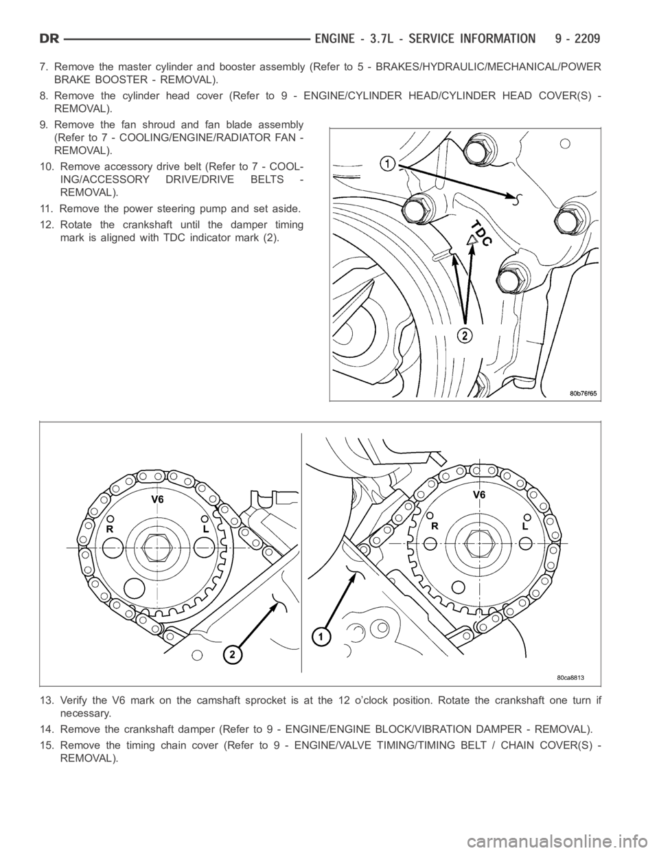
12. Rotate the crankshaft until the damper timing
mark is aligned with TDC indicator mark (2).
13. Verify the V6 mark on the camshaft sprocket is at the 12 o’clock position. Rotate the crankshaft one turn if
necessary.
14. Remove the crankshaft damper (Refer to 9 - ENGINE/ENGINE BLOCK/VIBRATION DAMPER - REMOVAL).
15. Remove the timing chain cover (Refer to 9 - ENGINE/VALVE TIMING/TIMINGBELT / CHAIN COVER(S) -
REMOVAL).