Page 439 of 5267

3.EXCESSIVE RESISTANCE IN THE BATTERY CIRCUIT
Turn the ignition off.
Check the Battery Cables for excessive resistance using the service information procedure.
Did either Battery Cable have a voltage drop greater than 0.2 of a volt?
Ye s>>
Repair the excessive resistance in the Battery circuit.
Perform the POWERTRAIN VERIFICATION TEST. (Refer to 9 - ENGINE - STANDARD PROCEDURE)
No>>
Go To 4
4.STARTER RELAY
Turn ignition off.
Remove the Starter Relay from IPM.
CAUTION: The Parking Brake must be on and the Transmission must be in park for a vehicle equipped with
an automatic transmission.
WARNING: When the engine is operating, do not stand in direct line with the fan. Do not put your hands
near the pulleys, belts, or fan. Do notwear loose clothing. Failure to follow these instructions can result in
personal injury or death.
Briefly connect a jumper wire from the Internal Fused B+ circuit to the (T750) Starter Relay Output circuit.
Did the Starter Motor crank the engine?
Ye s>>
Go To 5
No>>
Go To 7
5.(T751) FUSED IGNITION SWITCH OUTPUT CIRCUIT
Ignition on, engine not running.
Using a 12-volt test light, probe the (T751) Fused Ignition Switch Output circuit in the Starter Relay connector.
While observing 12-volt test light, hold ignition key in the start position.
Does the test light illuminate brightly?
Ye s>>
Go To 6
No>>
Repair the excessive resistance in the(T751)FusedIgnitionSwitchOutput circuit. Inspect related fuses
and repair as necessary.
Perform the POWERTRAIN VERIFICATION TEST. (Refer to 9 - ENGINE - STANDARD PROCEDURE)
Page 880 of 5267

4.BATTERY CABLE OPEN
Measure the resistance of the battery cable between the battery and the intake air heater relay for both relays.
Is the resistance less than 10 Ohms?
Ye s>>
Go To 5
No>>
Replace the battery cable from the battery to the Intake Air Heater Relay.
Perform POWERTRAIN VERIFICATION TEST VER - 1 (DIESEL). (Refer to 8 - ELECTRICAL/ELEC-
TRONIC CONTROL MODULES/ENGINE CONTROL MODULE - DIAGNOSIS AND TESTING)
5.#1 INTAKE AIR HEATER RELAY
Disconnect the #1 intake air heater relay signal wire.
Connect a jumper wire from the signal terminal of the #1 intake air heater relay to battery positive.
Did the relay click when 12 volts was applied?
Ye s>>
Go To 6
No>>
Replace #1 Intake Air Heater Relay.
Perform POWERTRAIN VERIFICATION TEST VER - 1 (DIESEL). (Refer to 8 - ELECTRICAL/ELEC-
TRONIC CONTROL MODULES/ENGINE CONTROL MODULE - DIAGNOSIS AND TESTING)
6.#2 INTAKE AIR HEATER RELAY
Disconnect the #2 intake air heater relay signal wire.
Connect a jumper wire from the signal terminal of the #2 intake air heater relay to battery positive.
Did the relay click when 12 volts was applied?
Ye s>>
Refer to the INTERMITTENT CONDITIONSymptom (Diagnostic Procedure).
No>>
Replace #2 Intake Air Heater Relay.
Perform POWERTRAIN VERIFICATION TEST VER - 1 (DIESEL). (Refer to 8 - ELECTRICAL/ELEC-
TRONIC CONTROL MODULES/ENGINE CONTROL MODULE - DIAGNOSIS AND TESTING)
Page 3716 of 5267

Theory of Operation
The transmission throttle valve cable has been replace by the transmission throttle valve actuator (TTVA). The TTVA
consists of an electric DC motor, two potentiometers, and a gear drive system. The TTVA is mechanically connected
to the transmission throttle valve in the valve body by the “D” shaped opening in the bottom of the TTVA shaft.
The Transmission Throttle Valve Actuator (TTVA) does not require any mechanical adjustments. All changes in throt-
tle valve position are controlled by the Engine Control Module (ECM).
The TTVA does require an initialization period after the actuator has beenremoved or replaced. After the actuator
has been removed or replaced, move the ignition to the ON position for thirty (30) seconds. This will allow the ECM
sufficient time to perform the internal calibration procedures to learn the TTVA’s current “zero” position.
When Monitored:
Continuously with the ignition on.
Set Condition:
When the Engine Control Module (ECM) detects the monitored Transmission Throttle Valve Position Sensor
voltage drops below a predetermined value.
Possible Causes
(K312) TTVA POSITION SENSOR SIGNAL CIRCUIT OPEN
(K312) TTVA POSITION SENSOR SIGNAL CIRCUIT SHORT TO GROUND
(K312) TTVA POSITION SENSOR SIGNAL CIRCUIT SHORT TO ANOTHER CIRCUIT
(F856) 5 VOLT SUPPLY CIRCUIT OPEN
(F856) 5 VOLT SUPPLY CIRCUIT SHORT TO GROUND
(F856) 5 VOLT SUPPLY CIRCUIT SHORT TO ANOTHER CIRCUIT
TRANSMISSION THROTTLE VALVE ACTUATOR
ENGINE CONTROL MODULE
Always perform the Pre-Diagnostic Troubleshooting procedure before proceeding. (Refer to 21 - TRANSMIS-
SION/TRANSAXLE/AUTOMATIC - 48RE - STANDARD PROCEDURE)
Diagnostic Test
1.CHECK THE TTVA
Ignition on, engine not running.
With the scan tool, record and erase Engine DTCs.
Turn the ignition off to the lock position.
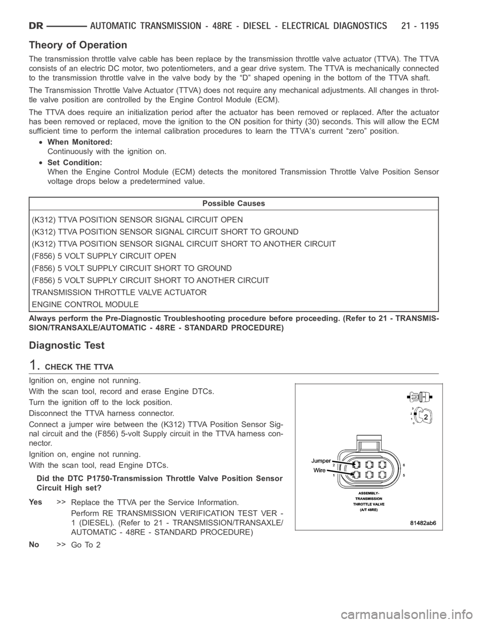
Disconnect the TTVA harness connector.
Connect a jumper wire between the (K312) TTVA Position Sensor Sig-
nal circuit and the (F856) 5-volt Supply circuit in the TTVA harness con-
nector.
Ignition on, engine not running.
With the scan tool, read Engine DTCs.
Did the DTC P1750-Transmission Throttle Valve Position Sensor
Circuit High set?
Ye s>>
Replace the TTVA per the Service Information.
Perform RE TRANSMISSION VERIFICATION TEST VER -
1 (DIESEL). (Refer to 21 - TRANSMISSION/TRANSAXLE/
AUTOMATIC - 48RE - STANDARD PROCEDURE)
No>>
Go To 2