2006 DODGE RAM SRT-10 fuel filter location
[x] Cancel search: fuel filter locationPage 1907 of 5267
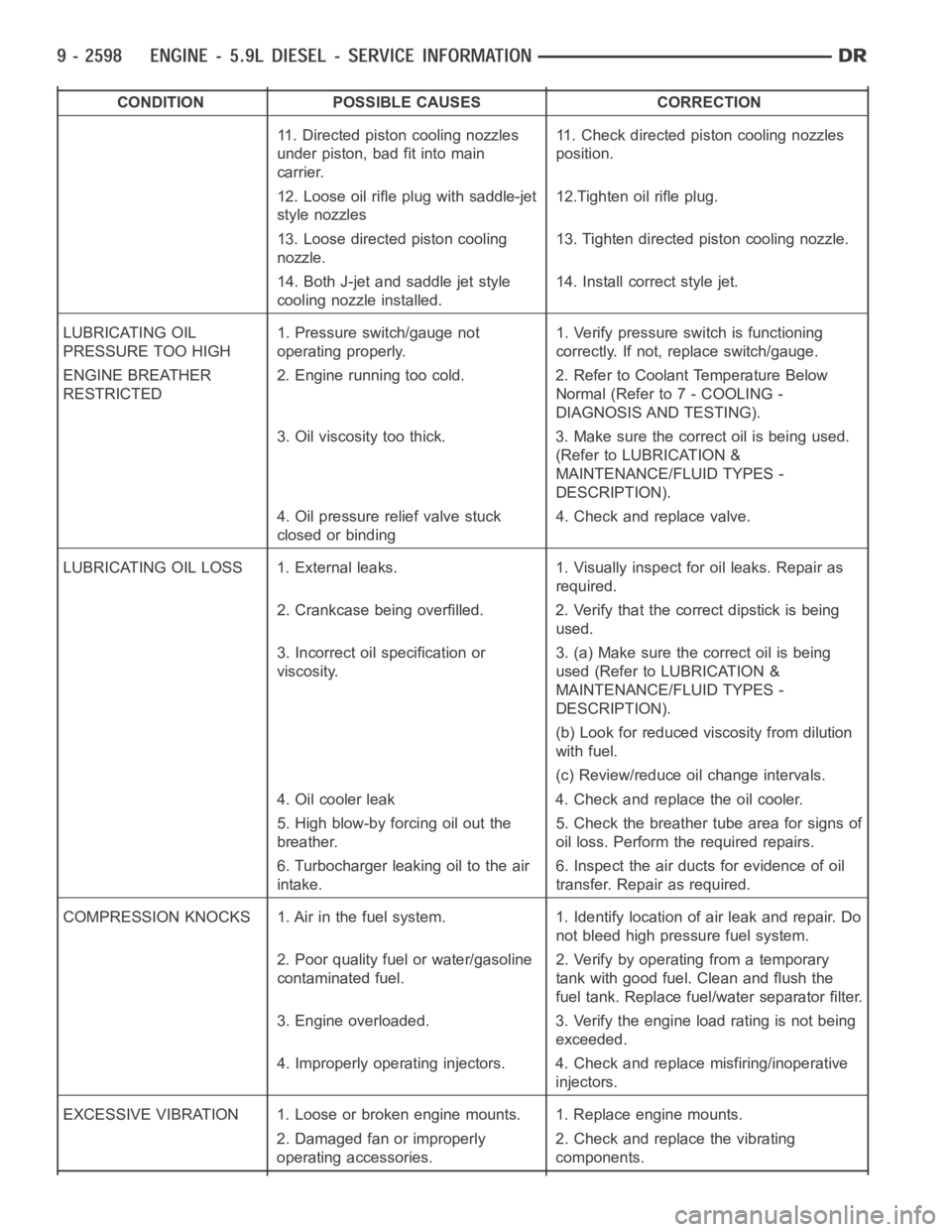
CONDITION POSSIBLE CAUSES CORRECTION
11. Directed piston cooling nozzles
under piston, bad fit into main
carrier.11. Check directed piston cooling nozzles
position.
12. Loose oil rifle plug with saddle-jet
style nozzles12.Tighten oil rifle plug.
13. Loose directed piston cooling
nozzle.13. Tighten directed piston cooling nozzle.
14. Both J-jet and saddle jet style
cooling nozzle installed.14. Install correct style jet.
LUBRICATING OIL
PRESSURE TOO HIGH1. Pressure switch/gauge not
operating properly.1. Verify pressure switch is functioning
correctly. If not, replace switch/gauge.
ENGINE BREATHER
RESTRICTED2. Engine running too cold. 2. Refer to Coolant Temperature Below
Normal (Refer to 7 - COOLING -
DIAGNOSIS AND TESTING).
3. Oil viscosity too thick. 3. Make sure the correct oil is being used.
(Refer to LUBRICATION &
MAINTENANCE/FLUID TYPES -
DESCRIPTION).
4. Oil pressure relief valve stuck
closed or binding4. Check and replace valve.
LUBRICATING OIL LOSS 1. External leaks. 1. Visually inspect for oil leaks.Repair as
required.
2. Crankcase being overfilled. 2. Verify that the correct dipstick is being
used.
3. Incorrect oil specification or
viscosity.3. (a) Make sure the correct oil is being
used (Refer to LUBRICATION &
MAINTENANCE/FLUID TYPES -
DESCRIPTION).
(b) Look for reduced viscosity from dilution
with fuel.
(c) Review/reduce oil change intervals.
4. Oil cooler leak 4. Check and replace the oil cooler.
5. High blow-by forcing oil out the
breather.5. Check the breather tube area for signs of
oil loss. Perform the required repairs.
6. Turbocharger leaking oil to the air
intake.6. Inspect the air ducts for evidence of oil
transfer. Repair as required.
COMPRESSION KNOCKS 1. Air in the fuel system. 1. Identify location of air leak and repair. Do
not bleed high pressure fuel system.
2. Poor quality fuel or water/gasoline
contaminated fuel.2. Verify by operating from a temporary
tank with good fuel. Clean and flush the
fuel tank. Replace fuel/water separator filter.
3. Engine overloaded. 3. Verify the engine load rating is not being
exceeded.
4. Improperly operating injectors. 4. Check and replace misfiring/inoperative
injectors.
EXCESSIVE VIBRATION 1. Loose or broken engine mounts. 1. Replace engine mounts.
2. Damaged fan or improperly
operating accessories.2. Check and replace the vibrating
components.
Page 1938 of 5267
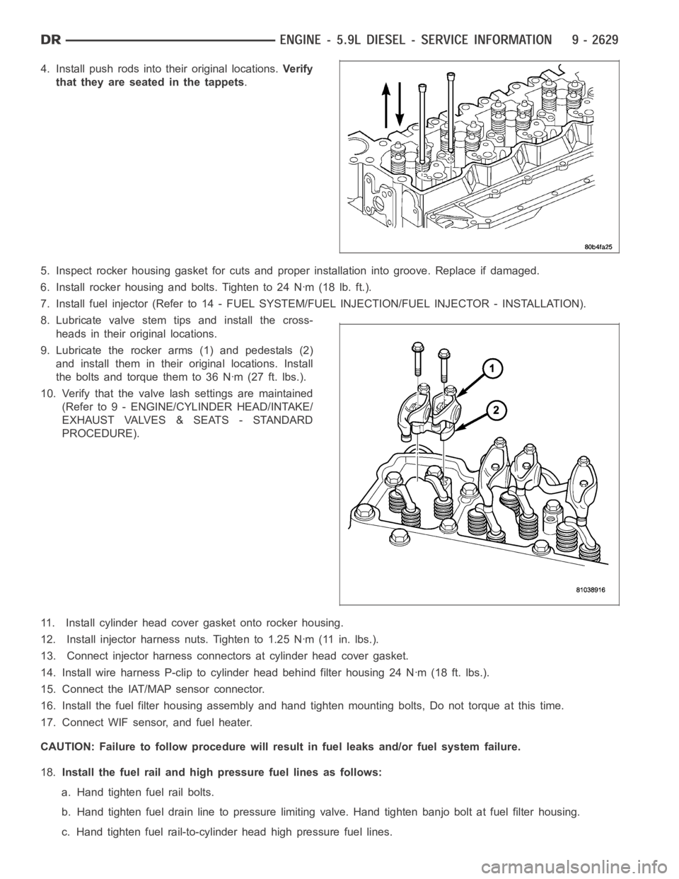
4. Install push rods into their original locations.Ve r i f y
that they are seated in the tappets.
5. Inspect rocker housing gasket for cuts and proper installation into groove. Replace if damaged.
6. Install rocker housing and bolts. Tighten to 24 Nꞏm (18 lb. ft.).
7. Install fuel injector (Refer to 14 - FUEL SYSTEM/FUEL INJECTION/FUEL INJECTOR - INSTALLATION).
8. Lubricate valve stem tips and install the cross-
heads in their original locations.
9. Lubricate the rocker arms (1) and pedestals (2)
and install them in their original locations. Install
the bolts and torque them to 36 Nꞏm (27 ft. lbs.).
10. Verify that the valve lash settings are maintained
(Refer to 9 - ENGINE/CYLINDER HEAD/INTAKE/
EXHAUST VALVES & SEATS - STANDARD
PROCEDURE).
11. Install cylinder head cover gasket onto rocker housing.
12. Install injector harness nuts. Tighten to 1.25 Nꞏm (11 in. lbs.).
13. Connect injector harness connectors at cylinder head cover gasket.
14. Install wire harness P-clip to cylinder head behind filter housing 24 Nꞏm (18 ft. lbs.).
15. Connect the IAT/MAP sensor connector.
16. Install the fuel filter housing assembly and hand tighten mounting bolts, Do not torque at this time.
17. Connect WIF sensor, and fuel heater.
CAUTION: Failure to follow procedure will result in fuel leaks and/or fuelsystem failure.
18.Install the fuel rail and high pressure fuel lines as follows:
a. Hand tighten fuel rail bolts.
b. Hand tighten fuel drain line to pressure limiting valve. Hand tighten banjo bolt at fuel filter housing.
c. Hand tighten fuel rail-to-cylinder head high pressure fuel lines.
Page 1939 of 5267
d. Install fuel line brace bolts-to-intake manifold finger tight for fuellines#2thru#5.
e. Install fuel line brace nut to rear lift bracket stud, finger tight, for fuel line #6.
f. Hand tighten fuel pump to fuel rail line.
g. Torque fuel line nuts at cylinder head to 30 Nꞏm ( 22 ft. lbs.).
h. Torque fuel line nuts at fuel rail to 30 Nꞏm (22 ft. lbs.)
i. Usingabackupwrench,torquefuelpumptofuelraillineto37Nꞏm(27ft.lbs.). At injection pump.
j. Torque fuel pump to fuel rail line to 37 Nꞏm (27 ft. lbs.) at fuel rail.
k. Torque fuel drain banjo bolt at pressure limiting valve and front of fuelfilter housing to 24 Nꞏm (18 ft. lbs.).
l. Torque fuel line brace bolts to 24 Nꞏm (18 ft. lbs.).
m. Torque fuel line brace nut to 24 Nꞏm (18 ft. lbs.).
n. Torque rail bolts to 24 Nꞏm (18 ft. lbs.).
o. Connect fuel pressure sensor.
p. Torque fuel filter mounting bolts to 24 Nꞏm (18 ft. lbs.).
19. Reposition number 6 fuel line shield and torque to 43 Nꞏm (32 ft. lbs.).
20. Install the fuel filter to injection pump low pressure line. Inspect and replace sealing washers if necessary.
Torque banjo bolts to 24 Nꞏm (18 ft. lbs.).
21. Connect fuel return line at back of cylinder head hand tight.
22. Connect fuel return line at filter housing hand tight.
23. Torque banjo connections at cylinder head and fuel filter housing to 24Nꞏm (18 ft. lbs.)
24. Install bracket to rear of filter housing. Torque to 24 Nꞏm (18 ft. lbs.).
25. Using new gaskets, install the intake grid heater and air inlet housing. Torque bolts to 24 Nꞏm (18 ft. lbs.).
26. Install wire harness P-clip and push on clip to air inlet housing.
27. Connect engine oil level indicator tube at fuel filter housing and at air inlet housing.
28. Install the charge air cooler-to-air inlet housing duct assembly. Torque all clamps to 11 Nꞏm (100 in. lbs.).
29. Connect intake grid heater wires.
30. Secure engine harness to front of cylinder head with bolt at four locations.
31. Connect engine coolant temperature sensor connector.
32. Connect radiator upper hose to thermostat housing.
33. Rotate generator into position. Install upper bolt and torque upper and lower bolts.
34. Install wire harness push-on clip below bracket.
35. Install wire harness P-clip to top of bracket.
36. Install fan support and torque to 32 Nꞏm (24 ft. lbs.).
37. Install cooling fan/drive refer to (Refer to 7 - COOLING/ENGINE/RADIATOR FAN - INSTALLATION).
38. Install accessory drive belt (Refer to 7 - COOLING/ACCESSORY DRIVE/DRIVE BELTS - INSTALLATION).
39. Install exhaust manifold/turbocharger assembly, using new gaskets.Start all bolts/spacers by hand. Starting
from the center bolts out, Torque bolts to 43 Nꞏm (32 ft. lbs.), then retorque from the center out again.
40. Install exhaust manifold heat shield to exhaust manifold studs. Install retaining nuts.Torque to 24 Nꞏm (18 ft.
lbs.).
41. Install exhaust bolt retention straps across cylinders 5 & 6.
42. Using a new gasket, connect the turbocharger oil drain tube. Torque to 24Nꞏm(18ft.lbs.).
43. Perform the turbocharger pre-lube procedure. (Refer to 11 - EXHAUST SYSTEM/TURBOCHARGER SYSTEM/
TURBOCHARGER - INSTALLATION)
44. Connect the turbocharger oil supply line. Torque to 24 Nꞏm (18 ft. lbs.).
45. Install air cleaner housing and duct.
46. Connect air inlet temperature/pressure sensor.
47. Raise vehicle on hoist.
Page 2088 of 5267
OIL
STANDARD PROCEDURE
CHECKING ENGINE OIL LEVEL
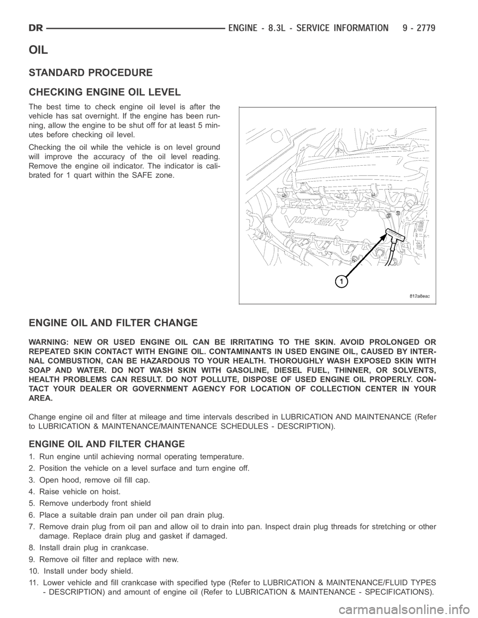
The best time to check engine oil level is after the
vehicle has sat overnight. If the engine has been run-
ning, allow the engine to be shut off for at least 5 min-
utes before checking oil level.
Checking the oil while the vehicle is on level ground
will improve the accuracy of the oil level reading.
Remove the engine oil indicator. The indicator is cali-
brated for 1 quart within the SAFE zone.
ENGINE OIL AND FILTER CHANGE
WARNING: NEW OR USED ENGINE OIL CAN BE IRRITATING TO THE SKIN. AVOID PROLONGED OR
REPEATED SKIN CONTACT WITH ENGINE OIL. CONTAMINANTS IN USED ENGINE OIL, CAUSED BY INTER-
NAL COMBUSTION, CAN BE HAZARDOUS TO YOUR HEALTH. THOROUGHLY WASH EXPOSED SKIN WITH
SOAP AND WATER. DO NOT WASH SKIN WITH GASOLINE, DIESEL FUEL, THINNER, OR SOLVENTS,
HEALTH PROBLEMS CAN RESULT. DO NOT POLLUTE, DISPOSE OF USED ENGINE OIL PROPERLY. CON-
TACT YOUR DEALER OR GOVERNMENT AGENCY FOR LOCATION OF COLLECTION CENTER INYOUR
AREA.
Change engine oil and filter at mileage and time intervals described in LUBRICATION AND MAINTENANCE (Refer
to LUBRICATION & MAINTENANCE/MAINTENANCE SCHEDULES - DESCRIPTION).
ENGINE OIL AND FILTER CHANGE
1. Run engine until achieving normal operating temperature.
2. Position the vehicle on a level surface and turn engine off.
3. Open hood, remove oil fill cap.
4. Raise vehicle on hoist.
5. Remove underbody front shield
6. Place a suitable drain pan under oil pan drain plug.
7. Remove drain plug from oil pan and allow oil to drain into pan. Inspect drain plug threads for stretching or other
damage. Replace drain plug and gasket if damaged.
8. Install drain plug in crankcase.
9. Remove oil filter and replace with new.
10. Install under body shield.
11. Lower vehicle and fill crankcase with specified type (Refer to LUBRICATION & MAINTENANCE/FLUID TYPES
- DESCRIPTION) and amount of engine oil (Refer to LUBRICATION & MAINTENANCE - SPECIFICATIONS).
Page 2241 of 5267
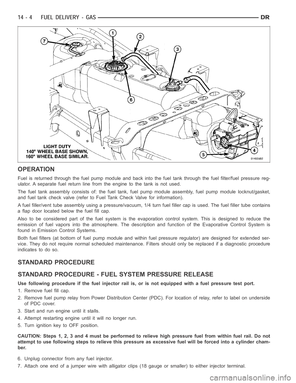
OPERATION
Fuel is returned through the fuel pump module and back into the fuel tank through the fuel filter/fuel pressure reg-
ulator. A separate fuel return line from the engine to the tank is not used.
The fuel tank assembly consists of: the fuel tank, fuel pump module assembly, fuel pump module locknut/gasket,
and fuel tank check valve (refer to Fuel Tank Check Valve for information).
A fuel filler/vent tube assembly using apressure/vacuum,1/4 turn fuel filler cap is used. The fuel filler tube contains
a flap door located below the fuel fill cap.
Also to be considered part of the fuelsystem is the evaporation control system. This is designed to reduce the
emission of fuel vapors into the atmosphere. The description and functionof the Evaporative Control System is
found in Emission Control Systems.
Both fuel filters (at bottom of fuel pump module and within fuel pressure regulator) are designed for extended ser-
vice. They do not require normal scheduled maintenance. Filters should only be replaced if a diagnostic procedure
indicates to do so.
STANDARD PROCEDURE
STANDARD PROCEDURE - FUEL SYSTEM PRESSURE RELEASE
Use following procedure if the fuel injector rail is, or is not equipped with a fuel pressure test port.
1. Remove fuel fill cap.
2. Remove fuel pump relay from Power Distribution Center (PDC). For location of relay, refer to label on underside
of PDC cover.
3. Start and run engine until it stalls.
4. Attempt restarting engine until it will no longer run.
5. Turn ignition key to OFF position.
CAUTION: Steps 1, 2, 3 and 4 must be performed to relieve high pressure fuel from within fuel rail. Do not
attempt to use following steps to relieve this pressure as excessive fuel will be forced into a cylinder cham-
ber.
6. Unplug connector from any fuel injector.
7. Attach one end of a jumper wire with alligator clips (18 gauge or smaller)to either injector terminal.
Page 5235 of 5267
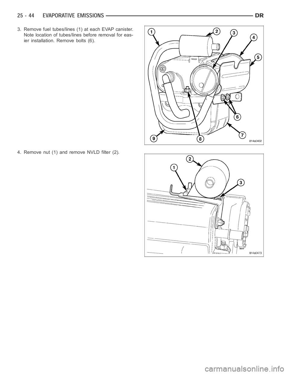
3. Remove fuel tubes/lines (1) at each EVAP canister.
Note location of tubes/lines before removal for eas-
ier installation. Remove bolts (6).
4. Remove nut (1) and remove NVLD filter (2).