2006 DODGE RAM SRT-10 hood open
[x] Cancel search: hood openPage 1451 of 5267
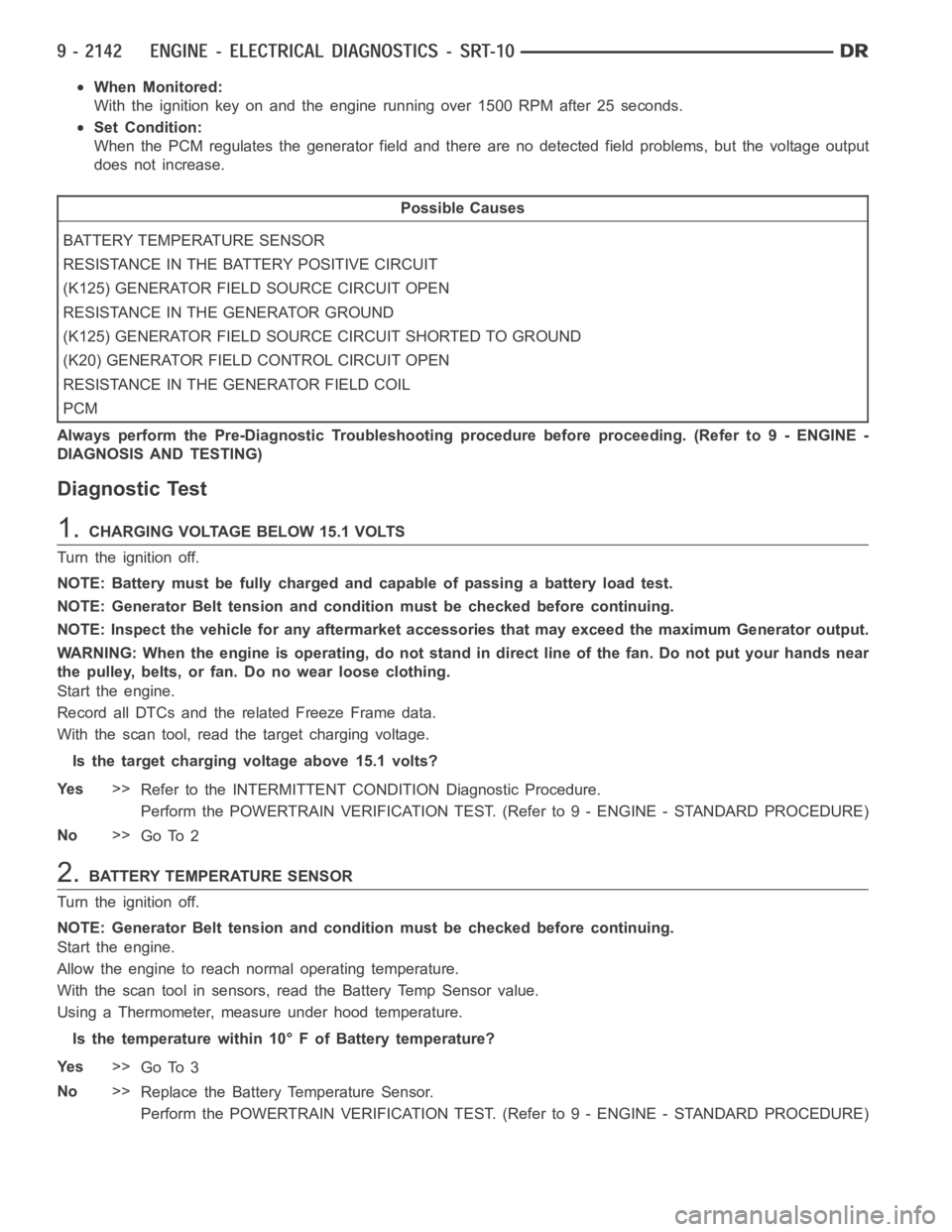
When Monitored:
With the ignition key on and the engine running over 1500 RPM after 25 seconds.
Set Condition:
When the PCM regulates the generator field and there are no detected field problems, but the voltage output
does not increase.
Possible Causes
BATTERY TEMPERATURE SENSOR
RESISTANCE IN THE BATTERY POSITIVE CIRCUIT
(K125) GENERATOR FIELD SOURCE CIRCUIT OPEN
RESISTANCE IN THE GENERATOR GROUND
(K125) GENERATOR FIELD SOURCE CIRCUIT SHORTED TO GROUND
(K20) GENERATOR FIELD CONTROL CIRCUIT OPEN
RESISTANCE IN THE GENERATOR FIELD COIL
PCM
Always perform the Pre-Diagnostic Troubleshooting procedure before proceeding. (Refer to 9 - ENGINE -
DIAGNOSIS AND TESTING)
Diagnostic Test
1.CHARGING VOLTAGE BELOW 15.1 VOLTS
Turn the ignition off.
NOTE: Battery must be fully charged and capable of passing a battery load test.
NOTE: Generator Belt tension and condition must be checked before continuing.
NOTE: Inspect the vehicle for any aftermarket accessories that may exceedthe maximum Generator output.
WARNING: When the engine is operating, do not stand in direct line of the fan. Do not put your hands near
the pulley, belts, or fan. Do no wear loose clothing.
Start the engine.
Record all DTCs and the related Freeze Frame data.
With the scan tool, read the target charging voltage.
Is the target charging voltage above 15.1 volts?
Ye s>>
Refer to the INTERMITTENT CONDITION Diagnostic Procedure.
Perform the POWERTRAIN VERIFICATION TEST. (Refer to 9 - ENGINE - STANDARD PROCEDURE)
No>>
Go To 2
2.BATTERY TEMPERATURE SENSOR
Turn the ignition off.
NOTE: Generator Belt tension and condition must be checked before continuing.
Start the engine.
Allow the engine to reach normal operating temperature.
With the scan tool in sensors, read the Battery Temp Sensor value.
Using a Thermometer, measure under hood temperature.
Is the temperature within 10° F of Battery temperature?
Ye s>>
Go To 3
No>>
Replace the Battery Temperature Sensor.
Perform the POWERTRAIN VERIFICATION TEST. (Refer to 9 - ENGINE - STANDARD PROCEDURE)
Page 2088 of 5267
OIL
STANDARD PROCEDURE
CHECKING ENGINE OIL LEVEL
The best time to check engine oil level is after the
vehicle has sat overnight. If the engine has been run-
ning, allow the engine to be shut off for at least 5 min-
utes before checking oil level.
Checking the oil while the vehicle is on level ground
will improve the accuracy of the oil level reading.
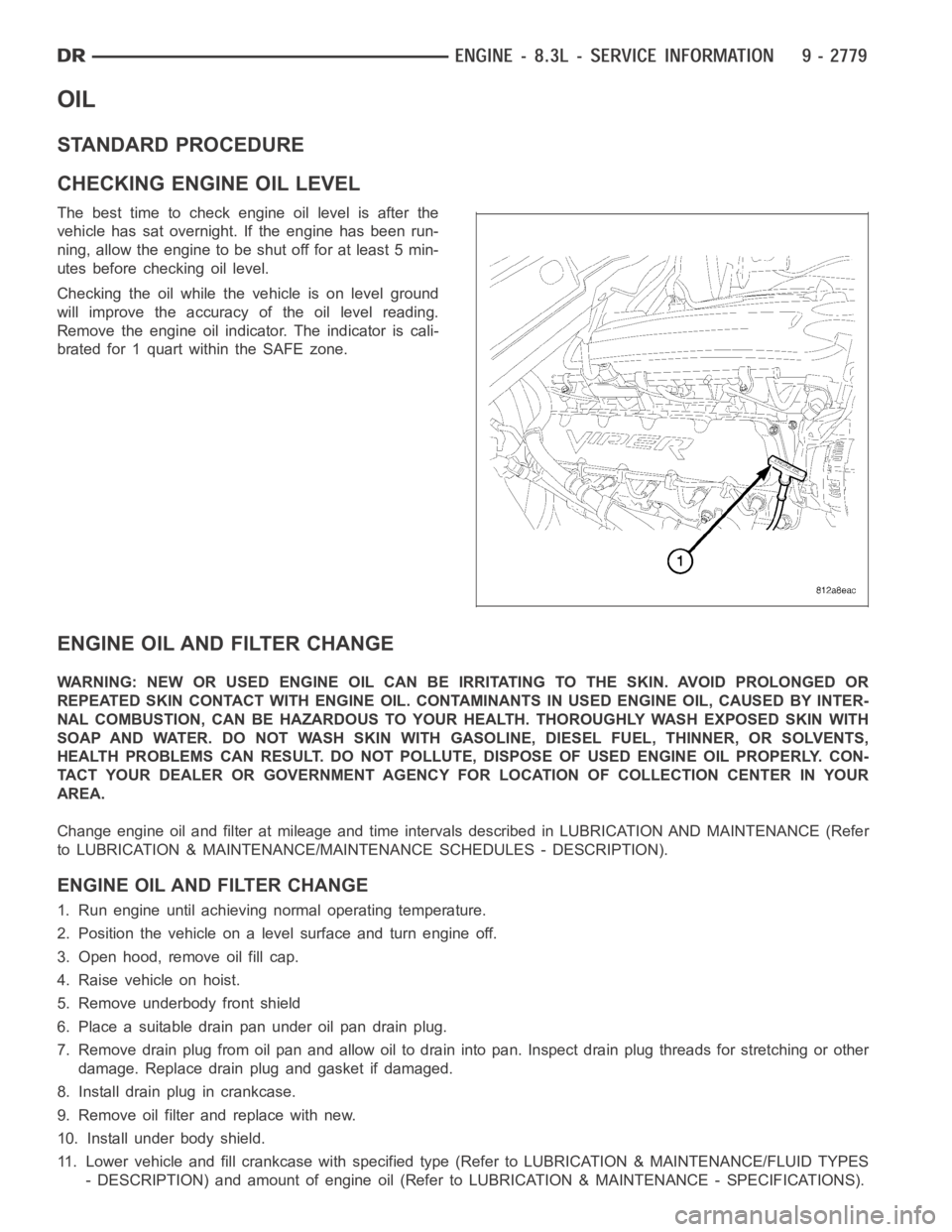
Remove the engine oil indicator. The indicator is cali-
brated for 1 quart within the SAFE zone.
ENGINE OIL AND FILTER CHANGE
WARNING: NEW OR USED ENGINE OIL CAN BE IRRITATING TO THE SKIN. AVOID PROLONGED OR
REPEATED SKIN CONTACT WITH ENGINE OIL. CONTAMINANTS IN USED ENGINE OIL, CAUSED BY INTER-
NAL COMBUSTION, CAN BE HAZARDOUS TO YOUR HEALTH. THOROUGHLY WASH EXPOSED SKIN WITH
SOAP AND WATER. DO NOT WASH SKIN WITH GASOLINE, DIESEL FUEL, THINNER, OR SOLVENTS,
HEALTH PROBLEMS CAN RESULT. DO NOT POLLUTE, DISPOSE OF USED ENGINE OIL PROPERLY. CON-
TACT YOUR DEALER OR GOVERNMENT AGENCY FOR LOCATION OF COLLECTION CENTER INYOUR
AREA.
Change engine oil and filter at mileage and time intervals described in LUBRICATION AND MAINTENANCE (Refer
to LUBRICATION & MAINTENANCE/MAINTENANCE SCHEDULES - DESCRIPTION).
ENGINE OIL AND FILTER CHANGE
1. Run engine until achieving normal operating temperature.
2. Position the vehicle on a level surface and turn engine off.
3. Open hood, remove oil fill cap.
4. Raise vehicle on hoist.
5. Remove underbody front shield
6. Place a suitable drain pan under oil pan drain plug.
7. Remove drain plug from oil pan and allow oil to drain into pan. Inspect drain plug threads for stretching or other
damage. Replace drain plug and gasket if damaged.
8. Install drain plug in crankcase.
9. Remove oil filter and replace with new.
10. Install under body shield.
11. Lower vehicle and fill crankcase with specified type (Refer to LUBRICATION & MAINTENANCE/FLUID TYPES
- DESCRIPTION) and amount of engine oil (Refer to LUBRICATION & MAINTENANCE - SPECIFICATIONS).
Page 4216 of 5267
SWITCH-SELECTOR
DESCRIPTION
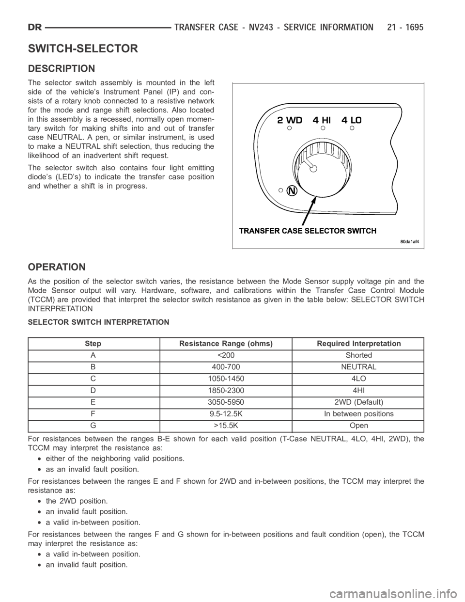
The selector switch assembly is mounted in the left
side of the vehicle’s Instrument Panel (IP) and con-
sists of a rotary knob connected to a resistive network
for the mode and range shift selections. Also located
in this assembly is a recessed, normally open momen-
tary switch for making shifts into and out of transfer
case NEUTRAL. A pen, or similar instrument, is used
to make a NEUTRAL shift selection, thus reducing the
likelihood of an inadvertent shift request.
The selector switch also contains four light emitting
diode’s (LED’s) to indicate the transfer case position
and whether a shift is in progress.
OPERATION
As the position of the selector switchvaries, the resistance between the Mode Sensor supply voltage pin and the
Mode Sensor output will vary. Hardware, software, and calibrations within the Transfer Case Control Module
(TCCM) are provided that interpret the selector switch resistance as giveninthetablebelow:SELECTORSWITCH
INTERPRETATION
SELECTOR SWITCH INTERPRETATION
Step Resistance Range (ohms) Required Interpretation
A <200 Shorted
B 400-700 NEUTRAL
C 1050-1450 4LO
D 1850-2300 4HI
E 3050-5950 2WD (Default)
F 9.5-12.5K In between positions
G>15.5KOpen
For resistances between the ranges B-E shown for each valid position (T-Case NEUTRAL, 4LO, 4HI, 2WD), the
TCCM may interpret the resistance as:
either of the neighboring valid positions.
as an invalid fault position.
For resistances between the ranges E and F shown for 2WD and in-between positions, the TCCM may interpret the
resistance as:
the 2WD position.
an invalid fault position.
a valid in-between position.
For resistances between the ranges F and G shown for in-between positions and fault condition (open), the TCCM
may interpret the resistance as:
a valid in-between position.
an invalid fault position.
Page 4260 of 5267
SWITCH-TRANSFER CASE SELECTOR
DESCRIPTION
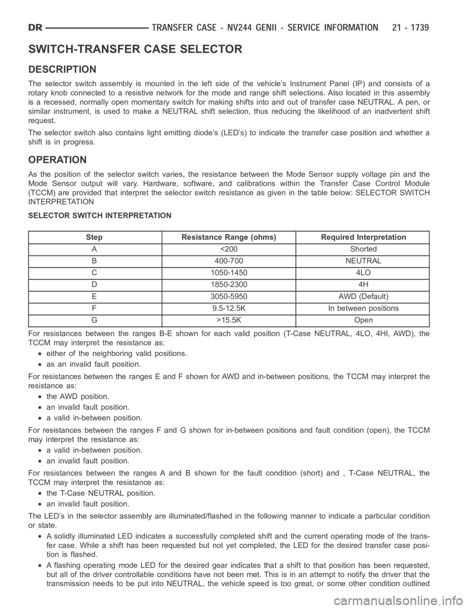
The selector switch assembly is mounted in the left side of the vehicle’s Instrument Panel (IP) and consists of a
rotary knob connected to a resistive network for the mode and range shift selections. Also located in this assembly
is a recessed, normally open momentary switch for making shifts into and out of transfer case NEUTRAL. A pen, or
similar instrument, is used to make a NEUTRAL shift selection, thus reducing the likelihood of an inadvertent shift
request.
The selector switch also contains light emitting diode’s (LED’s) to indicate the transfer case position and whether a
shift is in progress.
OPERATION
As the position of the selector switchvaries, the resistance between the Mode Sensor supply voltage pin and the
Mode Sensor output will vary. Hardware, software, and calibrations within the Transfer Case Control Module
(TCCM) are provided that interpret the selector switch resistance as giveninthetablebelow:SELECTORSWITCH
INTERPRETATION
SELECTOR SWITCH INTERPRETATION
Step Resistance Range (ohms) Required Interpretation
A <200 Shorted
B 400-700 NEUTRAL
C 1050-1450 4LO
D 1850-2300 4H
E 3050-5950 AWD (Default)
F 9.5-12.5K In between positions
G>15.5KOpen
For resistances between the ranges B-E shown for each valid position (T-Case NEUTRAL, 4LO, 4HI, AWD), the
TCCM may interpret the resistance as:
either of the neighboring valid positions.
as an invalid fault position.
For resistances between the ranges E and F shown for AWD and in-between positions, the TCCM may interpret the
resistance as:
the AWD position.
an invalid fault position.
a valid in-between position.
For resistances between the ranges F and G shown for in-between positions and fault condition (open), the TCCM
may interpret the resistance as:
a valid in-between position.
an invalid fault position.
For resistances between the ranges A and B shown for the fault condition (short) and , T-Case NEUTRAL, the
TCCM may interpret the resistance as:
the T-Case NEUTRAL position.
an invalid fault position.
The LED’s in the selector assembly are illuminated/flashed in the following manner to indicate a particular condition
or state.
A solidly illuminated LED indicates asuccessfully completed shift and the current operating mode of the trans-
fer case. While a shift has been requested but not yet completed, the LED forthe desired transfer case posi-
tion is flashed.
A flashing operating mode LED for the desired gear indicates that a shift tothat position has been requested,
but all of the driver controllable conditions have not been met. This is in an attempt to notify the driver that the
transmission needs to be put into NEUTRAL, the vehicle speed is too great, or some other condition outlined
Page 4310 of 5267
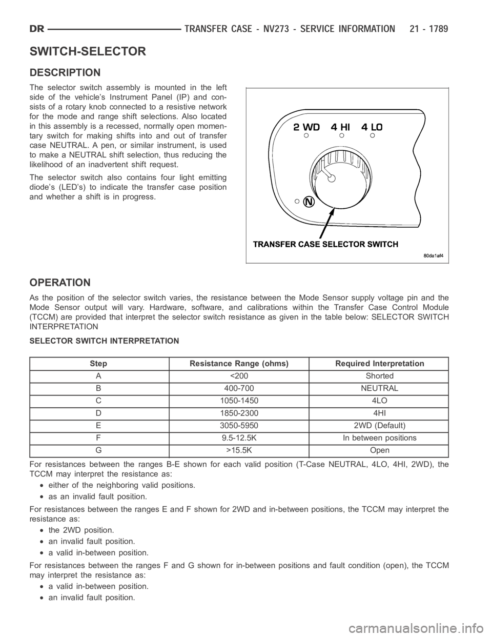
SWITCH-SELECTOR
DESCRIPTION
The selector switch assembly is mounted in the left
side of the vehicle’s Instrument Panel (IP) and con-
sists of a rotary knob connected to a resistive network
for the mode and range shift selections. Also located
in this assembly is a recessed, normally open momen-
tary switch for making shifts into and out of transfer
case NEUTRAL. A pen, or similar instrument, is used
to make a NEUTRAL shift selection, thus reducing the
likelihood of an inadvertent shift request.
The selector switch also contains four light emitting
diode’s (LED’s) to indicate the transfer case position
and whether a shift is in progress.
OPERATION
As the position of the selector switchvaries, the resistance between the Mode Sensor supply voltage pin and the
Mode Sensor output will vary. Hardware, software, and calibrations within the Transfer Case Control Module
(TCCM) are provided that interpret the selector switch resistance as giveninthetablebelow:SELECTORSWITCH
INTERPRETATION
SELECTOR SWITCH INTERPRETATION
Step Resistance Range (ohms) Required Interpretation
A <200 Shorted
B 400-700 NEUTRAL
C 1050-1450 4LO
D 1850-2300 4HI
E 3050-5950 2WD (Default)
F 9.5-12.5K In between positions
G>15.5KOpen
For resistances between the ranges B-E shown for each valid position (T-Case NEUTRAL, 4LO, 4HI, 2WD), the
TCCM may interpret the resistance as:
either of the neighboring valid positions.
as an invalid fault position.
For resistances between the ranges E and F shown for 2WD and in-between positions, the TCCM may interpret the
resistance as:
the 2WD position.
an invalid fault position.
a valid in-between position.
For resistances between the ranges F and G shown for in-between positions and fault condition (open), the TCCM
may interpret the resistance as:
a valid in-between position.
an invalid fault position.
Page 4434 of 5267
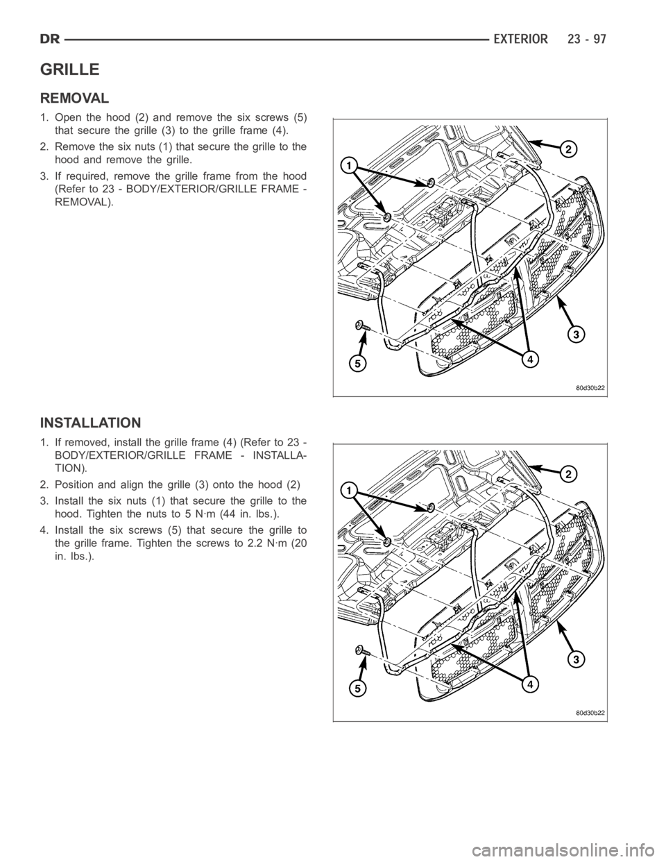
GRILLE
REMOVAL
1. Open the hood (2) and remove the six screws (5)
that secure the grille (3) to the grille frame (4).
2. Remove the six nuts (1) that secure the grille to the
hood and remove the grille.
3. If required, remove the grille frame from the hood
(Refer to 23 - BODY/EXTERIOR/GRILLE FRAME -
REMOVAL).
INSTALLATION
1. If removed, install the grille frame (4) (Refer to 23 -
BODY/EXTERIOR/GRILLE FRAME - INSTALLA-
TION).
2. Position and align the grille (3) onto the hood (2)
3. Install the six nuts (1) that secure the grille to the
hood. Tighten the nuts to 5 Nꞏm (44 in. lbs.).
4. Install the six screws (5) that secure the grille to
the grille frame. Tighten the screws to 2.2 Nꞏm (20
in. lbs.).
Page 4446 of 5267
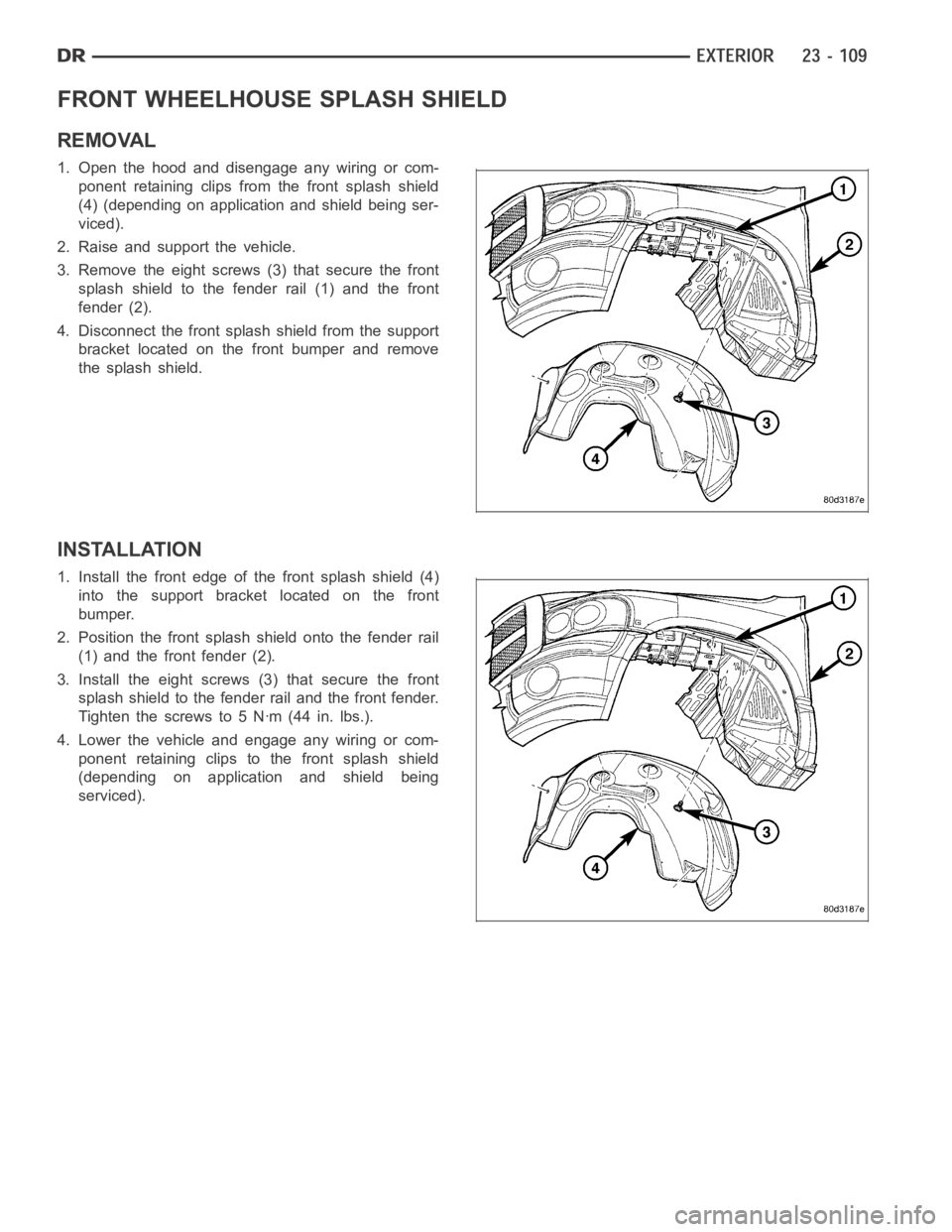
FRONT WHEELHOUSE SPLASH SHIELD
REMOVAL
1. Open the hood and disengage any wiring or com-
ponent retaining clips from the front splash shield
(4) (depending on application and shield being ser-
viced).
2. Raise and support the vehicle.
3. Remove the eight screws (3) that secure the front
splash shield to the fender rail (1) and the front
fender (2).
4. Disconnect the front splash shield from the support
bracket located on the front bumper and remove
the splash shield.
INSTALLATION
1. Install the front edge of the front splash shield (4)
into the support bracket located on the front
bumper.
2. Position the front splash shield onto the fender rail
(1) and the front fender (2).
3. Install the eight screws (3) that secure the front
splash shield to the fender rail and the front fender.
Tighten the screws to 5 Nꞏm (44 in. lbs.).
4. Lower the vehicle and engage any wiring or com-
ponent retaining clips to the front splash shield
(depending on application and shield being
serviced).
Page 4465 of 5267
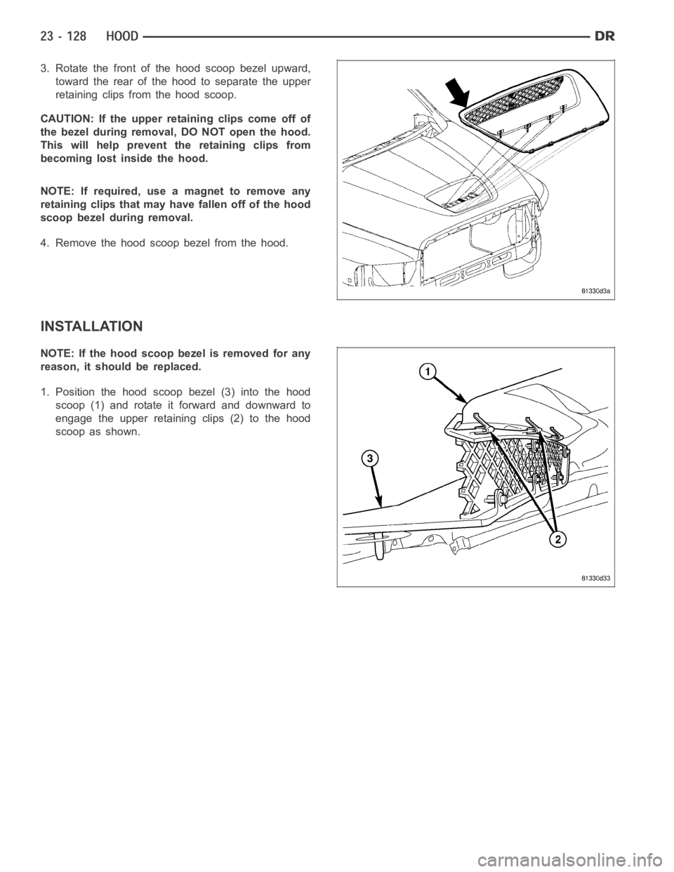
3. Rotate the front of the hood scoop bezel upward,
toward the rear of the hood to separate the upper
retaining clips from the hood scoop.
CAUTION: If the upper retaining clips come off of
the bezel during removal, DO NOT open the hood.
This will help prevent the retaining clips from
becoming lost inside the hood.
NOTE: If required, use a magnet to remove any
retaining clips that may have fallen off of the hood
scoop bezel during removal.
4. Remove the hood scoop bezel from the hood.
INSTALLATION
NOTE: If the hood scoop bezel is removed for any
reason, it should be replaced.
1. Position the hood scoop bezel (3) into the hood
scoop (1) and rotate it forward and downward to
engage the upper retaining clips (2) to the hood
scoop as shown.