2006 DODGE RAM SRT-10 air filter
[x] Cancel search: air filterPage 291 of 5267

2.RESTRICTED AIR INLET SYSTEM
Turn the ignition off.
Remove the Air Cleaner Assembly.
Remove the Air Filter.
Inspect the Throttle Body opening for signs of any foreign materials.
Check the intake tube / air cleaner for obstructions - include snow packingquestions to customer.
Were any restrictions found?
Ye s>>
Repair the restriction as necessary.
Perform the POWERTRAIN VERIFICATION TEST. (Refer to 9 - ENGINE - STANDARD PROCEDURE)
No>>
Go To 3
3.MAP SENSOR OPERATION
Start the engine.
With a scan tool, monitor the MAP Sensor voltage.
Snap the Accelerator pedal.
Does the MAP Sensor voltage vary from below 2.0 volts at idle to above 3.5 volts at Wide Open Throt-
tle?
Ye s>>
Go To 4
No>>
Go To 11
4.TP SENSOR OPERATION
Ignition on, engine not running.
With a scan tool, perform the Throttle Follower Test.
TP Sensor No.1 should start at approximately 0.8 of a volt and increase to 4.2volts.
TP Sensor No.2 should start at approximately 4.2 volts and decrease to 0.8 ofavolt.
Is the voltage transition smooth between the appropriate values?
Ye s>>
Refer to the INTERMITTENT CONDITION Diagnostic Procedure.
Perform the POWERTRAIN VERIFICATION TEST. (Refer to 9 - ENGINE - STANDARD PROCEDURE)
No>>
Go To 5
Page 301 of 5267

2.RESTRICTED AIR INLET SYSTEM
Turn the ignition off.
Remove the Air Cleaner Assembly.
Remove the Air Filter.
Inspect the Throttle Body opening for signs of any foreign materials.
Check the intake tube / air cleaner for obstructions - include snow packingquestions to customer.
Were any restrictions found?
Ye s>>
Repair the restriction as necessary.
Perform the POWERTRAIN VERIFICATION TEST. (Refer to 9 - ENGINE - STANDARD PROCEDURE)
No>>
Go To 3
3.MAP SENSOR OPERATION
Start the engine.
With a scan tool, monitor the MAP Sensor voltage.
Snap the Accelerator pedal.
Does the MAP Sensor voltage vary from below 2.0 volts at idle to above 3.5 volts at Wide Open Throt-
tle?
Ye s>>
Go To 4
No>>
Go To 11
4.TP SENSOR OPERATION
Ignition on, engine not running.
With a scan tool, perform the Throttle Follower Test.
TP Sensor No.1 should start at approximately 0.8 of a volt and increase to 4.2volts.
TP Sensor No.2 should start at approximately 4.2 volts and decrease to 0.8 ofavolt.
Is the voltage transition smooth between the appropriate values?
Ye s>>
Refer to the INTERMITTENT CONDITION Diagnostic Procedure.
Perform the POWERTRAIN VERIFICATION TEST. (Refer to 9 - ENGINE - STANDARD PROCEDURE)
No>>
Go To 5
Page 593 of 5267

When Monitored:
Whileengineisrunning.
Set Condition:
The boost pressure is lower than the expected boost pressure based on engine operating conditions.
Possible Causes
OTHER DTC’S
INTAKE AIR SYSTEM RESTRICTION
TURBO CHARGER DAMAGED
INTAKE AIR SYSTEM LEAK
BOOST PRESSURE SENSOR
BOOST PRESSURE SENSOR
TURBOCHARGER
INTERMITTENT CONDITION
Always perform the Pre-Diagnostic Troubleshooting procedure before proceeding. (Refer to 9 - ENGINE -
DIAGNOSIS AND TESTING)
Diagnostic Test
1.OTHER DTC’S
Turn the ignition on.
With the scan tool, read the Engine DTC’s.
Do you have other DTC’s?
Ye s>>
Repair other boost related DTC’s first.
Perform POWERTRAIN VERIFICATION TEST VER - 1 (DIESEL). (Refer to 8 - ELECTRICAL/ELEC-
TRONIC CONTROL MODULES/ENGINE CONTROL MODULE - DIAGNOSIS AND TESTING)
No>>
Go To 2
2.INTAKE AIR SYSTEM RESTRICTION
Inspect the air filter and intake air system for signs of restriction.
Were any restrictions found?
Ye s>>
Replace the Air Filter or repair the Intake air system for restriction.
Perform POWERTRAIN VERIFICATION TEST VER - 1 (DIESEL). (Refer to 8 - ELECTRICAL/ELEC-
TRONIC CONTROL MODULES/ENGINE CONTROL MODULE - DIAGNOSIS AND TESTING)
No>>
Go To 3
3.TURBO CHARGER DAMAGED
Disconnect the air cleaner connection to the turbo charger.
Using the service manual as a guide, visually inspect the turbo charger blades and turbo housing for signs of dam-
age.
Was any damaged found?
Ye s>>
Replace The Turbo charger.
Perform POWERTRAIN VERIFICATION TEST VER - 1 (DIESEL). (Refer to 8 - ELECTRICAL/ELEC-
TRONIC CONTROL MODULES/ENGINE CONTROL MODULE - DIAGNOSIS AND TESTING)
No>>
Go To 4
Page 885 of 5267

3.INJECTION SYSTEM
Perform “*INJECTOR RETURN FLOW TEST”. If okay continue.
Check for correct injectors and injector shims.
Visuslly inspect injector wire nuts and pass through connectors for damageorcorrosion.
Is vehicle repaired?
Ye s>>
Repair complete.
Perform POWERTRAIN VERIFICATION TEST VER - 1 (DIESEL). (Refer to 8 - ELECTRICAL/ELEC-
TRONIC CONTROL MODULES/ENGINE CONTROL MODULE - DIAGNOSIS AND TESTING)
No>>
Go To 4
4.FUEL RETURN
Check for kinked or restricted fuel return lines.
Check fuel tank venting.
Is vehicle repaired?
Ye s>>
Repair complete.
Perform POWERTRAIN VERIFICATION TEST VER - 1 (DIESEL). (Refer to 8 - ELECTRICAL/ELEC-
TRONIC CONTROL MODULES/ENGINE CONTROL MODULE - DIAGNOSIS AND TESTING)
No>>
Go To 5
5.INTAKE SYSTEM
Check for inlet restriction, inspect air filter for excessive dirt/debris. Verify air intake lines are not kinked or restricted.
Check for air system leaks. Perform “*INTAKE AIR SYSTEM PRESSURE TEST - DIESEL”.
Inspect Turbocharger for wheel clearance and proper wastegate operation.
Is vehicle repaired?
Ye s>>
Repair complete.
Perform POWERTRAIN VERIFICATION TEST VER - 1 (DIESEL). (Refer to 8 - ELECTRICAL/ELEC-
TRONIC CONTROL MODULES/ENGINE CONTROL MODULE - DIAGNOSIS AND TESTING)
No>>
Go To 6
6.OTHER VEHICLE SYSTEMS
Verify proper operation of the Transmission Clutch.
Verify proper operation of the Transmission.
Verify proper operation of the Vehicle brakes (check for dragging).
Verify proper operation of the Cooling fan operation cycle time.
Verify proper operation of the Engine driven accessories.
Verify proper operation of the Accelerator pedal (restricted or out of calibration).
Is vehicle repaired?
Ye s>>
Repair complete.
Perform POWERTRAIN VERIFICATION TEST VER - 1 (DIESEL). (Refer to 8 - ELECTRICAL/ELEC-
TRONIC CONTROL MODULES/ENGINE CONTROL MODULE - DIAGNOSIS AND TESTING)
No>>
Go To 7
Page 889 of 5267

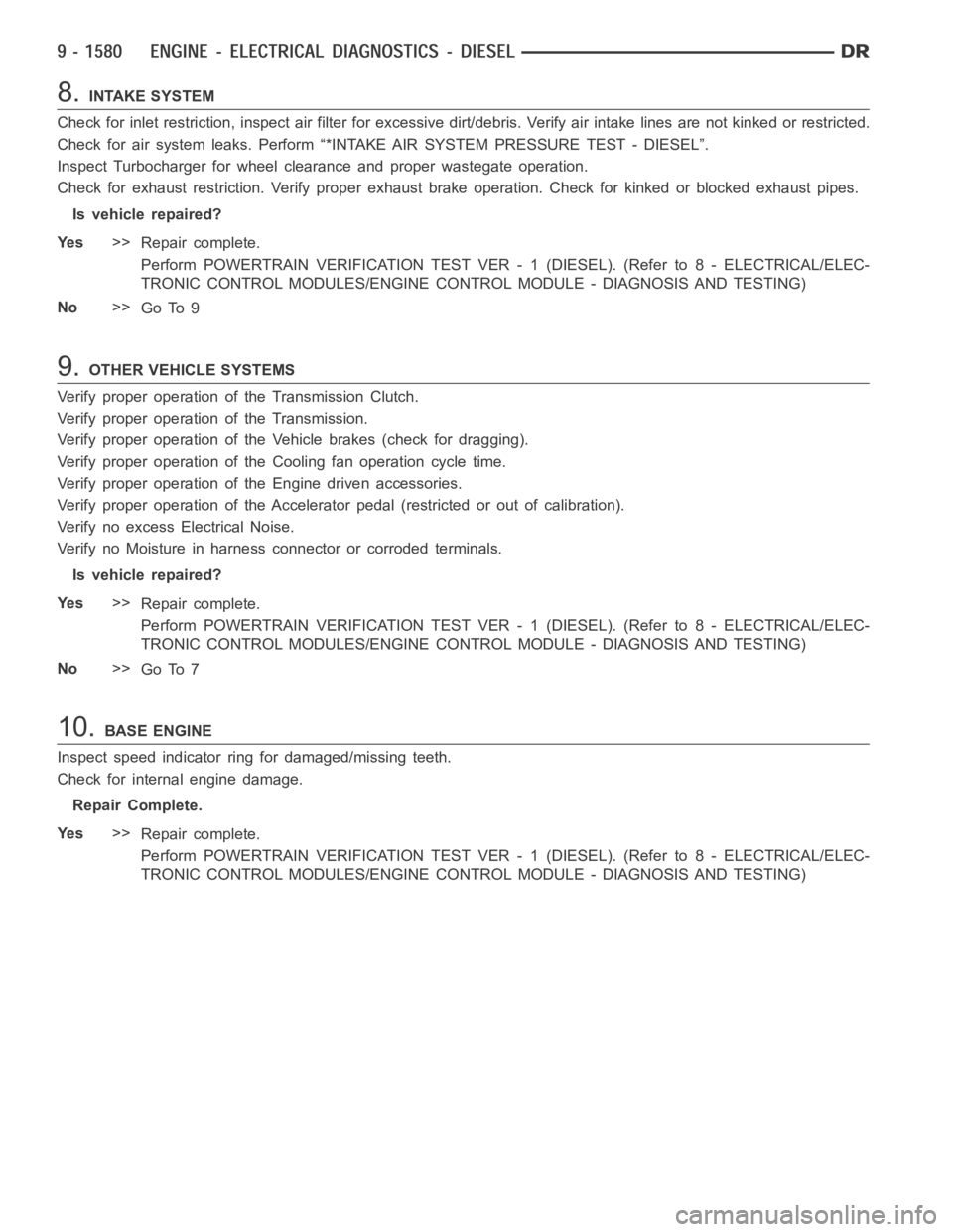
8.INTAKE SYSTEM
Check for inlet restriction, inspect air filter for excessive dirt/debris. Verify air intake lines are not kinked or restricted.
Check for air system leaks. Perform “*INTAKE AIR SYSTEM PRESSURE TEST - DIESEL”.
Inspect Turbocharger for wheel clearance and proper wastegate operation.
Check for exhaust restriction. Verify proper exhaust brake operation. Check for kinked or blocked exhaust pipes.
Is vehicle repaired?
Ye s>>
Repair complete.
Perform POWERTRAIN VERIFICATION TEST VER - 1 (DIESEL). (Refer to 8 - ELECTRICAL/ELEC-
TRONIC CONTROL MODULES/ENGINE CONTROL MODULE - DIAGNOSIS AND TESTING)
No>>
Go To 9
9.OTHER VEHICLE SYSTEMS
Verify proper operation of the Transmission Clutch.
Verify proper operation of the Transmission.
Verify proper operation of the Vehicle brakes (check for dragging).
Verify proper operation of the Cooling fan operation cycle time.
Verify proper operation of the Engine driven accessories.
Verify proper operation of the Accelerator pedal (restricted or out of calibration).
Verify no excess Electrical Noise.
Verify no Moisture in harness connector or corroded terminals.
Is vehicle repaired?
Ye s>>
Repair complete.
Perform POWERTRAIN VERIFICATION TEST VER - 1 (DIESEL). (Refer to 8 - ELECTRICAL/ELEC-
TRONIC CONTROL MODULES/ENGINE CONTROL MODULE - DIAGNOSIS AND TESTING)
No>>
Go To 7
10.BASE ENGINE
Inspect speed indicator ring for damaged/missing teeth.
Check for internal engine damage.
Repair Complete.
Ye s>>
Repair complete.
Perform POWERTRAIN VERIFICATION TEST VER - 1 (DIESEL). (Refer to 8 - ELECTRICAL/ELEC-
TRONIC CONTROL MODULES/ENGINE CONTROL MODULE - DIAGNOSIS AND TESTING)
Page 892 of 5267

1.
1. Using the Scan tool, check for DTCs. Troubleshoot any active DTCs beforeperforming this test.
2. Disconnect the wiring harness from the lift pump at the fuel tank module connector and inspect the pins for
damage. Fix or replace any damaged component.
3. Connect a voltmeter between the fuel lift pump supply and return pins at the fuel tank module connector.
4. Turn the ignition to the on position. Use the Scan tool to actuate the fuellift pump, record the voltage on the
voltmeter.
5. If the voltage is greater than 11.5 volts, go to step 14. If the voltage is lessthan11.5volts,gotostep6
6. Using a voltmeter, measure the battery voltage to determine that the voltage is greater than 11.5 volts. If the
voltage is greater than 11.5 volts, go to step 7. If the voltage is not greater than 11.5 volts, troubleshoot for low
battery voltage.
7. Remove the fuel lift pump relay from the PDC. Use a voltmeter to measure the voltage at the fuel lift pump relay
voltage supply pin in the PDC. If the voltage is greater than 11.5 volts, go to step 8. If the voltage is not greater than
11.5 volts, fix or replace the harness.
8. Remove the fuel lift pump relay from the PDC. Install a spare relay in place of the fuel lift pump relay. Using the
Scan tool, actuate the fuel lift pump. Use a voltmeter to measure the voltage between the fuel lift pump supply and
return pins at the fuel tank module connector while the fuel lift pump is actuated. If the voltage is greater than 11.5
volts, replace the fuel lift pump relay. If the voltage is not greater than 11.5volts,gotostep9.
9. Disconnect the wiring harness from the fuel tank module. Remove the liftpump relay from the PDC. Using an
Ohmmeter, measure the resistance of the fuel lift pump power supply wire between the PDC relay output pin and
the fuel tank module connector. If the resistance is less than 10 ohms, go tostep 10. If it is greater than 10 ohms,
fix or replace the harness.
10. Disconnect the wiring harness from the fuel tank module. Remove the fuel lift pump relay from the PDC. Using
a voltmeter, measure the voltage between battery negative and the fuel lift pump power supply wire at the fuel
module connector. If the voltage is less than 1 volt, go to step 11. If the voltage is greater than 1 volt, fix or replace
the harness.
11. Disconnect the wiring harness from the fuel tank module. Remove the fuel lift pump relay from the PDC. Using
an ohmmeter, measure the resistance between battery negative and the fuellift pump power supply wire at the fuel
module connector. If the resistance is less than 10 ohms, fix or replace theharness. If the resistance is greater than
10 ohms, go to step 12.
12. Disconnect the wiring harness from the fuel tank module. Using an Ohmmeter, measure the resistance of the
fuel lift pump ground wire between the fuel tank module connector and battery negative. If the resistance is less
than 10 ohms, go to step 13. If the resistance is greater than 10 ohms, fix or replace the harness.
13. Disconnect the wiring harness from the fuel tank module. Using a voltmeter, measure the voltage between the
fuel lift pump ground wire and battery negative. If the voltage is less than1 volt, go to step 14. If the voltage is
greater than 1 volt, fix or replace the harness.
14. Reconnect the lift pump connector.
FLOW TEST.
1. Remove the fuel pump supply banjo fitting from the fuel injection pump.
2. Install Miller Tool #9014 fuel system test fitting into the fuel injection pump.
3. Connect one end of a section of fuel hose to the test fitting.
4. Put the other end of the fuel hose into an empty fuel container.
5. Use the scan tool to actuate the fuel lift pump.
6. While the lift pump is running, move the fuel hose from the fuel canister into a 1000ml graduated cylinder for 10
seconds.
7. Read and record the amount of fuel in the graduated cylinder after 10 seconds.
8. If you have more than 430ml in the graduated cylinder after 10 seconds, the test has successfully passed.
9. If you have less than 430ml of fuel in the graduated cylinder, inspect thefuel supply line from the fuel tank to the
fuel filter housing and the fuel supply line between the fuel filter housing and the high pressure fuel pump for signs
of damage, replace as necessary. If no damage is found, replace the fuel filter and retest.
10.Verify the Screened Banjo Bolt at the outlet of the fuel filter is free ofdebris. If debris is found, rinse screen with
water, blow dry and reinstall. Retest vehicle. If flow meets specification then trace back the source of debris, if flow
is still below spec repair damaged component.
Page 894 of 5267

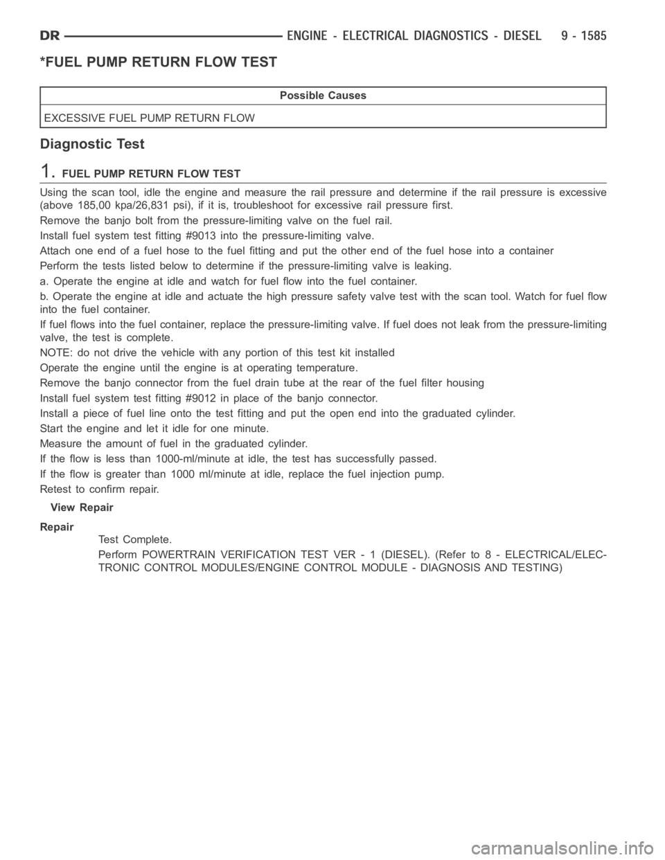
*FUEL PUMP RETURN FLOW TEST
Possible Causes
EXCESSIVE FUEL PUMP RETURN FLOW
Diagnostic Test
1.FUEL PUMP RETURN FLOW TEST
Using the scan tool, idle the engine and measure the rail pressure and determine if the rail pressure is excessive
(above 185,00 kpa/26,831 psi), if it is, troubleshoot for excessive rail pressure first.
Remove the banjo bolt from the pressure-limiting valve on the fuel rail.
Install fuel system test fitting #9013 into the pressure-limiting valve.
Attach one end of a fuel hose to the fuel fitting and put the other end of the fuel hose into a container
Perform the tests listed below to determine if the pressure-limiting valve is leaking.
a. Operate the engine at idle and watch for fuel flow into the fuel container.
b. Operate the engine at idle and actuate the high pressure safety valve test with the scan tool. Watch for fuel flow
into the fuel container.
If fuel flows into the fuel container, replace the pressure-limiting valve. If fuel does not leak from the pressure-limiting
valve, the test is complete.
NOTE: do not drive the vehicle with any portion of this test kit installed
Operate the engine until the engine is at operating temperature.
Remove the banjo connector from the fuel drain tube at the rear of the fuel filter housing
Install fuel system test fitting #9012 in place of the banjo connector.
Install a piece of fuel line onto the test fitting and put the open end into the graduated cylinder.
Start the engine and let it idle for one minute.
Measure the amount of fuel in the graduated cylinder.
If the flow is less than 1000-ml/minute at idle, the test has successfully passed.
If the flow is greater than 1000 ml/minute at idle, replace the fuel injection pump.
Retest to confirm repair.
View Repair
Repair
Te s t C o m p l e t e .
Perform POWERTRAIN VERIFICATION TEST VER - 1 (DIESEL). (Refer to 8 - ELECTRICAL/ELEC-
TRONIC CONTROL MODULES/ENGINE CONTROL MODULE - DIAGNOSIS AND TESTING)
Page 896 of 5267

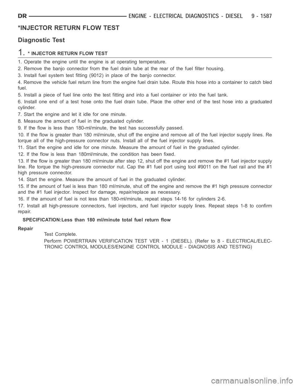
*INJECTOR RETURN FLOW TEST
Diagnostic Test
1.* INJECTOR RETURN FLOW TEST
1. Operate the engine until the engine is at operating temperature.
2. Remove the banjo connector from the fuel drain tube at the rear of the fuelfilter housing.
3. Install fuel system test fitting (9012) in place of the banjo connector.
4. Remove the vehicle fuel return line from the engine fuel drain tube. Route this hose into a container to catch bled
fuel.
5. Install a piece of fuel line onto the test fitting and into a fuel container or into the fuel tank.
6. Install one end of a test hose onto the fuel drain tube. Place the other endof the test hose into a graduated
cylinder.
7. Start the engine and let it idle for one minute.
8. Measure the amount of fuel in the graduated cylinder.
9. If the flow is less than 180-ml/minute, the test has successfully passed.
10. If the flow is greater than 180 ml/minute, shut off the engine and removeall of the fuel injector supply lines. Re
torque all of the high-pressure connector nuts. Install all of the fuel injector supply lines.
11. Start the engine and idle for one minute. Measure the amount of fuel in the graduated cylinder.
12. If the flow is less than 180ml/minute, the condition has been fixed.
13. If the flow is greater than 180 ml/minute after step 12, shut off the engine and remove the #1 fuel injector supply
line. Re torque the high-pressure connector nut. Cap the #1 fuel port usingtool #9011 on the fuel rail and the #1
high pressure connector.
14. Start the engine. Measure the amount of fuel in the graduated cylinder.
15. If the amount of fuel is less than 180 ml/minute, shut off the engine and remove the #1 high pressure connector
and the #1 fuel injector. Inspect for damage, repair/replace as necessary.
16. If the amount of fuel is not less than 180-ml/minute, repeat steps 14-16for cylinders 2-6.
17. Install all high-pressure connectors, fuel injectors, and fuel injector supply lines. Repeat steps 1-8 to confirm
repair.
SPECIFICATION:Less than 180 ml/minute total fuel return flow
Repair
Te s t C o m p l e t e .
Perform POWERTRAIN VERIFICATION TEST VER - 1 (DIESEL). (Refer to 8 - ELECTRICAL/ELEC-
TRONIC CONTROL MODULES/ENGINE CONTROL MODULE - DIAGNOSIS AND TESTING)