2006 DODGE RAM SRT-10 service schedule
[x] Cancel search: service schedulePage 1598 of 5267
OIL
STANDARD PROCEDURE - ENGINE OIL SERVICE
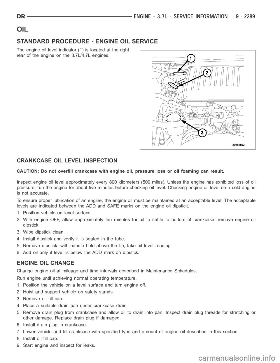
The engine oil level indicator (1) is located at the right
rear of the engine on the 3.7L/4.7L engines.
CRANKCASE OIL LEVEL INSPECTION
CAUTION: Do not overfill crankcase with engine oil, pressure loss or oil foaming can result.
Inspect engine oil level approximately every 800 kilometers (500 miles).Unless the engine has exhibited loss of oil
pressure, run the engine for about five minutes before checking oil level.Checking engine oil level on a cold engine
is not accurate.
To ensure proper lubrication of an engine, the engine oil must be maintained at an acceptable level. The acceptable
levels are indicated between the ADD and SAFE marks on the engine oil dipstick.
1. Position vehicle on level surface.
2. With engine OFF, allow approximately ten minutes for oil to settle to bottom of crankcase, remove engine oil
dipstick.
3. Wipe dipstick clean.
4. Install dipstick and verify it is seated in the tube.
5. Remove dipstick, with handle held above the tip, take oil level reading.
6. Add oil only if level is below the ADD mark on dipstick.
ENGINE OIL CHANGE
Change engine oil at mileage and time intervals described in Maintenance Schedules.
Run engine until achieving normal operating temperature.
1. Position the vehicle on a level surface and turn engine off.
2. Hoist and support vehicle on safety stands.
3. Remove oil fill cap.
4. Place a suitable drain pan under crankcase drain.
5. Remove drain plug from crankcase and allow oil to drain into pan. Inspectdrain plug threads for stretching or
other damage. Replace drain plug if damaged.
6. Install drain plug in crankcase.
7. Lower vehicle and fill crankcase with specified type and amount of engine oil described in this section.
8. Install oil fill cap.
9. Start engine and inspect for leaks.
Page 1723 of 5267
OIL
STANDARD PROCEDURE - ENGINE OIL SERVICE
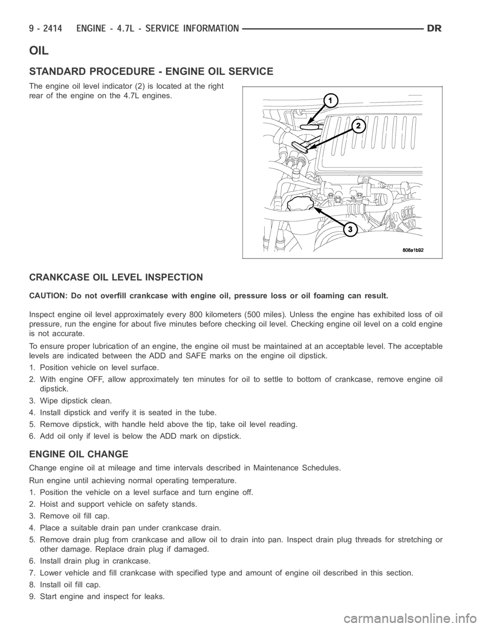
The engine oil level indicator (2) is located at the right
rear of the engine on the 4.7L engines.
CRANKCASE OIL LEVEL INSPECTION
CAUTION: Do not overfill crankcase with engine oil, pressure loss or oil foaming can result.
Inspect engine oil level approximately every 800 kilometers (500 miles).Unless the engine has exhibited loss of oil
pressure, run the engine for about five minutes before checking oil level.Checking engine oil level on a cold engine
is not accurate.
To ensure proper lubrication of an engine, the engine oil must be maintained at an acceptable level. The acceptable
levels are indicated between the ADD and SAFE marks on the engine oil dipstick.
1. Position vehicle on level surface.
2. With engine OFF, allow approximately ten minutes for oil to settle to bottom of crankcase, remove engine oil
dipstick.
3. Wipe dipstick clean.
4. Install dipstick and verify it is seated in the tube.
5. Remove dipstick, with handle held above the tip, take oil level reading.
6. Add oil only if level is below the ADD mark on dipstick.
ENGINE OIL CHANGE
Change engine oil at mileage and time intervals described in Maintenance Schedules.
Run engine until achieving normal operating temperature.
1. Position the vehicle on a level surface and turn engine off.
2. Hoist and support vehicle on safety stands.
3. Remove oil fill cap.
4. Place a suitable drain pan under crankcase drain.
5. Remove drain plug from crankcase and allow oil to drain into pan. Inspectdrain plug threads for stretching or
other damage. Replace drain plug if damaged.
6. Install drain plug in crankcase.
7. Lower vehicle and fill crankcase with specified type and amount of engine oil described in this section.
8. Install oil fill cap.
9. Start engine and inspect for leaks.
Page 1877 of 5267
OIL
STANDARD PROCEDURE - ENGINE OIL SERVICE
The engine oil level indicator is located at the left hand of the engine on the 5.7L engines.
CRANKCASE OIL LEVEL INSPECTION
CAUTION: Do not overfill crankcase with engine oil, pressure loss or oil foaming can result.
Inspect engine oil level approximately every 800 kilometers (500 miles).Unless the engine has exhibited loss of oil
pressure, run the engine for about ten minutes before checking oil level. Checking engine oil level on a cold engine
is not accurate.
To ensure proper lubrication of an engine, the engine oil must be maintained at an acceptable level. The acceptable
levels are indicated between the ADD and SAFE marks on the engine oil dipstick.
1. Position vehicle on level surface.
2. With engine OFF, allow approximately five minutes for oil to settle to bottom of crankcase, remove engine oil
dipstick.
3. Wipe dipstick clean.
4. Install dipstick and verify it is seated in the tube.
5. Remove dipstick, with handle held above the tip, take oil level reading.
6. Add oil only if level is below the ADD mark on dipstick.
ENGINE OIL CHANGE
Change engine oil at mileage and time intervals described in Maintenance Schedules (Refer to LUBRICATION &
MAINTENANCE/MAINTENANCESCHEDULES - DESCRIPTION).
Run engine until achieving normal operating temperature.
1. Position the vehicle on a level surface and turn engine off.
2. Hoist and support vehicle on safety stands.
3. Remove oil fill cap.
4. Place a suitable drain pan under crankcase drain.
5. Remove drain plug from crankcase and allow oil to drain into pan. Inspectdrain plug threads for stretching or
other damage. Replace drain plug if damaged.
6. Install drain plug in crankcase. Torque to 34 Nꞏm ( 25 ft. lbs.).
7. Lower vehicle and fill crankcase with specified type and amount of engine oil described in this section.
8. Install oil fill cap.
9. Start engine and inspect for leaks.
10. Stop engine and inspect oil level.
USED ENGINE OIL DISPOSAL
Care should be exercised when disposing used engine oil after it has been drained from a vehicle engine. Refer to
the WARNING at beginning of this section.
Page 2246 of 5267
FUEL FILTER/PRESSURE REGULATOR
DESCRIPTION
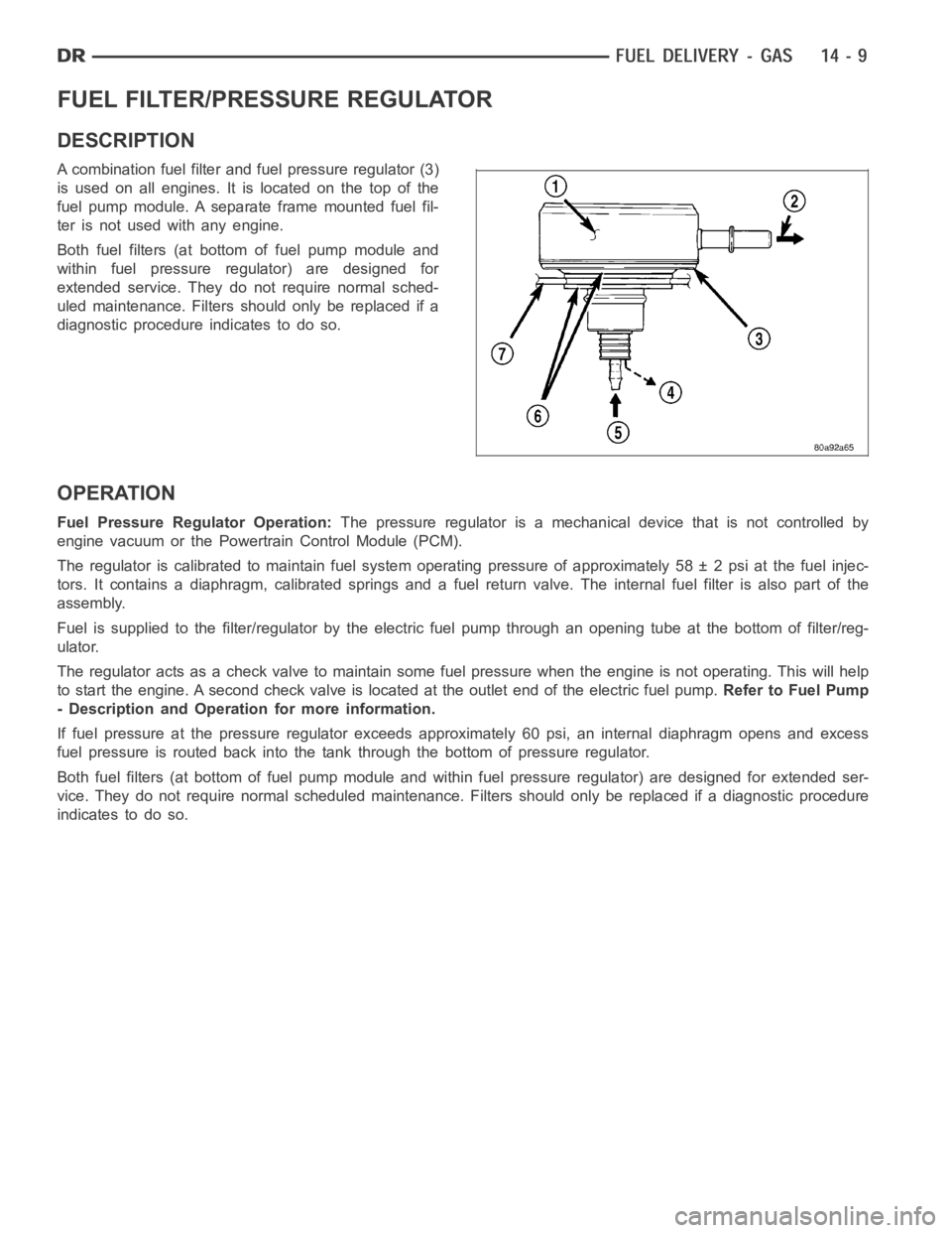
A combination fuel filter and fuel pressure regulator (3)
is used on all engines. It is located on the top of the
fuel pump module. A separate frame mounted fuel fil-
ter is not used with any engine.
Both fuel filters (at bottom of fuel pump module and
within fuel pressure regulator) are designed for
extended service. They do not require normal sched-
uled maintenance. Filters should only be replaced if a
diagnostic procedure indicates to do so.
OPERATION
Fuel Pressure Regulator Operation:The pressure regulator is a mechanical device that is not controlled by
engine vacuum or the Powertrain Control Module (PCM).
The regulator is calibrated to maintain fuel system operating pressure ofapproximately 58 ± 2 psi at the fuel injec-
tors. It contains a diaphragm, calibrated springs and a fuel return valve.The internal fuel filter is also part of the
assembly.
Fuel is supplied to the filter/regulator by the electric fuel pump throughan opening tube at the bottom of filter/reg-
ulator.
The regulator acts as a check valve to maintain some fuel pressure when the engine is not operating. This will help
to start the engine. A second check valve is located at the outlet end of the electric fuel pump.Refer to Fuel Pump
- Description and Operation for more information.
If fuel pressure at the pressure regulator exceeds approximately 60 psi, an internal diaphragm opens and excess
fuel pressure is routed back into the tank through the bottom of pressure regulator.
Both fuel filters (at bottom of fuel pump module and within fuel pressure regulator) are designed for extended ser-
vice. They do not require normal scheduled maintenance. Filters should only be replaced if a diagnostic procedure
indicates to do so.
Page 2472 of 5267
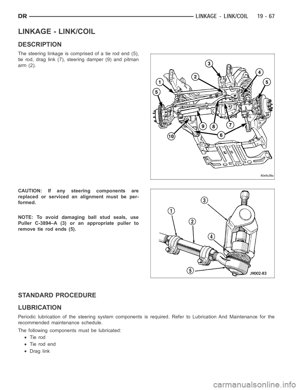
LINKAGE - LINK/COIL
DESCRIPTION
Thesteeringlinkageiscomprisedofatierodend(5),
tie rod, drag link (7), steering damper (9) and pitman
arm (2).
CAUTION: If any steering components are
replaced or serviced an alignment must be per-
formed.
NOTE: To avoid damaging ball stud seals, use
Puller C-3894–A (3) or an appropriate puller to
remove tie rod ends (5).
STANDARD PROCEDURE
LUBRICATION
Periodic lubrication of the steering system components is required. Refer to Lubrication And Maintenance for the
recommended maintenance schedule.
The following components must be lubricated:
Tie rod
Tie rod end
Drag link
Page 2726 of 5267
P0122-TPS/APP CIRCUIT LOW
For a complete wiring diagramRefer to Section 8W.
When Monitored:
Continuously with the ignition on and engine running.
Set Condition:
This DTC will set if the monitored TPS voltage drops below .078 volts for theperiod of 0.48 seconds.
Possible Causes
RELATED TPS ENGINE DTCS PRESENT
POWERTRAIN CONTROL MODULE
Always perform the Pre-Diagnostic Troubleshooting procedure before proceeding. (Refer to 21 - TRANSMIS-
SION/TRANSAXLE/AUTOMATIC - 42RLE - STANDARD PROCEDURE)
Theory of Operation
The powertrain controller receives the throttle position signal from theThrottle Position Sensor (TPS). The controller
provides the TPS with a 5 volt pull up and a sensor ground. The signal is checked for being out of range as well
as for intermittent operation (excessive signal changes). The engine controller transmits the throttle value onto the
Bus. Most engine controllers will calculate the throttle value if the throttle signal is lost. If an error is detected by the
transmission controller and the throttle value is available on the Bus, the Bus value will be used, normal operation
will continue, and a TPS code will be set. If an error is detected and the throttle value is not available on the Bus,
normal operation will be discontinued, a TPS DTC will be set, and the MIL will be turned on after 5 minutes of
calculated operation.
Diagnostic Test
1.DETERMINING IF RELATED ENGINE TPS DTCS ARE PRESENT
With the scan tool, check Engine DTCs, including pending DTCs and one trip failures.
Are there any Engine TPS DTCs present?
Ye s>>
Refer to the Driveability category and perform the appropriate diagnostic procedure.
Perform 42RLE TRANSMISSION VERIFICATION TEST - VER 1. (Refer to 21 - TRANSMISSION/
TRANSAXLE/AUTOMATIC - 42RLE - STANDARD PROCEDURE)
No>>
Go To 2
2.CHECK IF THE DTC IS CURRENT
With the scan tool, record the DTC EVENT DATA to help identify the conditionsinwhichtheDTCwasset.
With the scan tool, erase Transmission DTCs.
NOTE: To erase EVENT DATA information, a BATTERY DISCONNECT must be performed. Performing a BAT-
TERY DISCONNECT will reset all learned Transmission values to controllerdefaults which may lead to
erratic shift schedules.
Drive the vehicle and try to duplicate the conditions in which the DTC was reported by the DTC EVENT DATA.
With the scan tool, read Transmission DTCs.
Does this DTC reset?
Ye s>>
Using the schematics as a guide, check the Powertrain Control Module (PCM)terminals for corrosion,
damage, or terminal push out. Pay particular attention to all power and ground circuits. Check for Ser-
vice Information Tune-ups or Service Bulletins for any possible causes that may apply. If no problems
are found, replace the PCM per the Service Information. With the scan tool,perform QUICK LEARN.
Perform 42RLE TRANSMISSION VERIFICATION TEST - VER 1. (Refer to 21 - TRANSMISSION/
TRANSAXLE/AUTOMATIC - 42RLE - STANDARD PROCEDURE)
No>>
Go To 3
Page 2728 of 5267
P0123-TPS/APP CIRCUIT HIGH
For a complete wiring diagramRefer to Section 8W
When Monitored:
Continuously with the ignition on and engine running.
Set Condition:
This DTC will set if the monitored TPS voltage rises above 4.94 volts for theperiod of 0.48 seconds.
Possible Causes
RELATED TPS ENGINE DTCS PRESENT
POWERTRAIN CONTROL MODULE
Always perform the Pre-Diagnostic Troubleshooting procedure before proceeding. (Refer to 21 - TRANSMIS-
SION/TRANSAXLE/AUTOMATIC - 42RLE - STANDARD PROCEDURE)
Theory of Operation
The powertrain controller receives the throttle position signal from theThrottle Position Sensor (TPS). The controller
provides the TPS with a 5 volt pull up and a sensor ground. The signal is checked for being out of range as well
as for intermittent operation (excessive signal changes). The engine controller transmits the throttle value onto the
Bus. Most engine controllers will calculate the throttle value if the throttle signal is lost. If an error is detected by the
transmission controller and the throttle value is available on the Bus, the Bus value will be used, normal operation
will continue, and a TPS code will be set. If an error is detected and the throttle value is not available on the Bus,
normal operation will be discontinued, a TPS DTC will be set, and the MIL will be turned on after 5 minutes of
calculated operation.
Diagnostic Test
1.DETERMINING IF RELATED ENGINE TPS DTCS ARE PRESENT
With the scan tool, check Engine DTCs, including pending DTCs and one trip failures.
Are there any Engine TPS DTCs present?
Ye s>>
Refer to the Driveability category and perform the appropriate diagnostic procedure.
Perform 42RLE TRANSMISSION VERIFICATION TEST - VER 1. (Refer to 21 - TRANSMISSION/
TRANSAXLE/AUTOMATIC - 42RLE - STANDARD PROCEDURE)
No>>
Go To 2
2.CHECK TO SEE IF DTC IS CURRENT
With the scan tool, record the DTC EVENT DATA to help identify the conditionsinwhichtheDTCwasset.
With the scan tool, erase Transmission DTCs.
NOTE: To erase DTC EVENT DATA information, a BATTERY DISCONNECT must be performed. Performing a
BATTERY DISCONNECT will reset all learned Transmission values to controller defaults which may lead to
erratic shift schedules.
Drive the vehicle and try to duplicate the conditions in which the DTC was reported by the DTC EVENT DATA.
With the scan tool, read Transmission DTCs.
Does this DTC reset?
Ye s>>
Using the schematics as a guide, check the Powertrain Control Module (PCM)terminals for corrosion,
damage, or terminal push out. Pay particular attention to all power and ground circuits. Check for Ser-
vice Information Tune-ups or Service Bulletins for any possible causes that may apply. If no problems
are found, replace the PCM per the Service Information. With the scan tool,perform QUICK LEARN.
Perform 42RLE TRANSMISSION VERIFICATION TEST - VER 1. (Refer to 21 - TRANSMISSION/
TRANSAXLE/AUTOMATIC - 42RLE - STANDARD PROCEDURE)
No>>
Go To 3
Page 2732 of 5267
P0218-HIGH TEMPERATURE OPERATION ACTIVATED
For a complete wiring diagramRefer to Section 8W.
When Monitored:
Whenever the engine is running.
Set Condition:
Immediately when a Overheat shift schedule is activated when the Transmission Oil Temperature reaches 155°
C or 240° F.
Possible Causes
ENGINE COOLING SYSTEM OPERATION
TRANSMISSION OIL COOLER PLUGGED
H I G H T E M P E R AT U R E O P E R AT I O N S A C T I VAT E D
Always perform the Pre-Diagnostic Troubleshooting procedure before proceeding. (Refer to 21 - TRANSMIS-
SION/TRANSAXLE/AUTOMATIC - 42RLE - STANDARD PROCEDURE)
Theory of Operation
If the transmission oil temperature rises above 115° C (240° F), the overheat shift schedule is activated refer to
Transmission Operation as a function of Transmission Oil Temperature andthe code is set. The DTC is an infor-
mational code only and is being set to aid the technician in determining root cause of a customer driveability issue.
The code is also intended to alert the technician to determine if a cooling system malfunction has occurred or if an
additional transmission air to oil cooler should be added to the vehicle ifthe customer regularly drives in a manner
that overheats the transmission. Extended operation above 115° C (240° F)will reduce the durability of the trans-
mission and should be avoided. Correcting the cooling system malfunctionor installing an additional transmission oil
cooler will improve transmission durability especially for customers who operate in city/construction stop and go traf-
fic, tow trailers regularly, drive aggressively in low gear or drive regularly in mountainous areas.
Diagnostic Test
1.CHECK ENGINE COOLING SYSTEM
Perform Engine Cooling System diagnostics per the Service Information.
Is the Engine Cooling System functioning properly?
Ye s>>
Go To 2
No>>
Repair the cause of the engine overheating. Refer to the Service Information for the related diagnostic
or repair procedures.
Perform 42RLE TRANSMISSION VERIFICATION TEST - VER 1. (Refer to 21 - TRANSMISSION/
TRANSAXLE/AUTOMATIC - 42RLE - STANDARD PROCEDURE)
2.TRANSMISSION OIL COOLER RESTRICTED
Check the Transmission Oil Cooler Flow in accordance with the Service Information.
Is the transmission oil cooler restricted or plugged?
Ye s>>
Go To 3
No>>
Repair the cause of the plugged Transmission Oil Cooler as necessary and repair or replace the Trans-
mission Oil Cooler per the Service Information.
Perform 42RLE TRANSMISSION VERIFICATION TEST - VER 1. (Refer to 21 - TRANSMISSION/
TRANSAXLE/AUTOMATIC - 42RLE - STANDARD PROCEDURE)