2006 DODGE RAM SRT-10 seat adjustment
[x] Cancel search: seat adjustmentPage 1681 of 5267
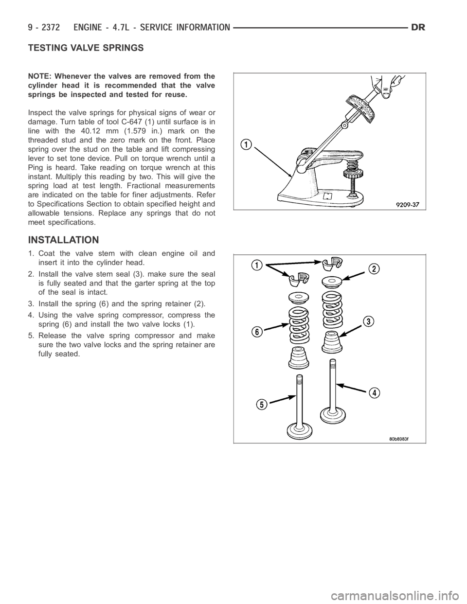
TESTING VALVE SPRINGS
NOTE: Whenever the valves are removed from the
cylinder head it is recommended that the valve
springs be inspected and tested for reuse.
Inspect the valve springs for physical signs of wear or
damage. Turn table of tool C-647 (1) until surface is in
line with the 40.12 mm (1.579 in.) mark on the
threaded stud and the zero mark on the front. Place
spring over the stud on the table and lift compressing
lever to set tone device. Pull on torque wrench until a
Ping is heard. Take reading on torque wrench at this
instant. Multiply this reading by two. This will give the
spring load at test length. Fractional measurements
are indicated on the table for finer adjustments. Refer
to Specifications Section to obtain specified height and
allowable tensions. Replace any springs that do not
meet specifications.
INSTALLATION
1. Coat the valve stem with clean engine oil and
insert it into the cylinder head.
2. Install the valve stem seal (3). make sure the seal
is fully seated and that the garter spring at the top
of the seal is intact.
3. Install the spring (6) and the spring retainer (2).
4. Using the valve spring compressor, compress the
spring (6) and install the two valve locks (1).
5. Release the valve spring compressor and make
sure the two valve locks and the spring retainer are
fully seated.
Page 1903 of 5267
page page
ENGINE - 5.9L DIESEL - SERVICE
INFORMATION
DESCRIPTION
DESCRIPTION - 5.9L DIESEL .............. 2596
DESCRIPTION - CRANKCASE BREATHER . . 2597
DIAGNOSIS AND TESTING
DIAGNOSIS AND TESTING - ENGINE
DIAGNOSIS - MECHANICAL............... 2597
DIAGNOSIS AND TESTING - SMOKE
DIAGNOSIS CHARTS..................... 2599
DIAGNOSIS AND TESTING - CYLINDER
COMPRESSION/LEAKAGE TESTS......... 2602
STANDARD PROCEDURE
STANDARD PROCEDURE - FORM-IN-
PLACE GASKETS AND SEALERS.......... 2603
STANDARD PROCEDURE - REPAIR
DAMAGED OR WORN THREADS.......... 2604
STANDARD PROCEDURE—HYDROSTATIC
LOCK.................................... 2604
REMOVAL - ENGINE ........................ 2605
INSTALLATION - ENGINE ................... 2610
SPECIFICATIONS
SPECIFICATIONS - 5.9L DIESEL ........... 2615
TORQUE ................................. 2617
SPECIAL TOOLS
5.9L DIESEL ENGINE ..................... 2619
ENGINE DATA PLATE
DESCRIPTION ............................. 2621
AIR CLEANER ELEMENT
REMOVAL ................................. 2622
INSTALLATION ............................. 2623
CYLINDER HEAD
DESCRIPTION ............................. 2624
REMOVAL ................................. 2624
CLEANING
CLEANING ............................... 2626
CLEANING—CROSSHEADS ............... 2626
CLEANING—PUSHRODS .................. 2626
INSPECTION
INSPECTION............................. 2627
INSPECTION - CROSSHEADS . . ........... 2627
INSPECTION—PUSHRODS................ 2628
INSTALLATION ............................. 2628
COVER - CYLINDER HEAD
REMOVAL
REMOVAL - ROCKER HOUSING ........... 2632
REMOVAL - CYL HEAD COVER ............ 2632
REMOVAL - CYL HEAD COVER GASKET . . . 2634
CLEANING
CLEANING CYLINDER HEAD COVER ...... 2634
INSPECTION - CYLINDER HEAD COVER ..... 2634INSTALLATION
INSTALLATION - ROCKER HOUSING ....... 2634
INSTALLATION - CYL HEAD COVER ....... 2635
INSTALLATION - CYL HEAD COVER
GASKET................................. 2636
VALVES & SEATS - INTAKE/EXHAUST
DESCRIPTION ............................. 2638
STANDARD PROCEDURE
STANDARD PROCEDURE - VALVES,
GUIDES AND SPRINGS................... 2638
STANDARD PROCEDURE - VALVE LASH
ADJUSTMENT AND VERIFICATION......... 2643
REMOVAL ................................. 2644
INSTALLATION ............................. 2646
ROCKER ARM
DESCRIPTION ............................. 2647
REMOVAL ................................. 2647
CLEANING ................................. 2648
INSPECTION............................... 2648
INSTALLATION ............................. 2649
ENGINE BLOCK
STANDARD PROCEDURE
STANDARD PROCEDURE - CYLINDER
BLOCK REFACING........................ 2651
STANDARD PROCEDURE - CYLINDER
BORE - DE-GLAZE........................ 2651
STANDARD PROCEDURE—CYLINDER
BORE REPAIR............................ 2652
STANDARD PROCEDURE - CAM BORE
REPAIR.................................. 2655
INSPECTION............................... 2655
CAMSHAFT & BEARINGS (IN BLOCK)
REMOVAL
CAMSHAFT BEARINGS................... 2657
CAMSHAFT .............................. 2657
INSPECTION
............................... 2659
INSTALLATION
CAMSHAFT BEARINGS................... 2661
CAMSHAFT .............................. 2661
BEARINGS - CONNECTING ROD
STANDARD PROCEDURE - CONNECTING
ROD BEARING AND CRANKSHAFT
JOURNAL CLEARANCE................... 2663
CRANKSHAFT & GEAR
DESCRIPTION ............................. 2664
REMOVAL - GEAR .......................... 2664
INSTALLATION - GEAR ..................... 2664
BEARINGS - CRANKSHAFT MAIN
STANDARD PROCEDURE - MAIN BEARING
CLEARANCE ............................. 2665
Page 1910 of 5267

EXCESSIVE WHITE SMOKE
POSSIBLE CAUSE CORRECTION
Fuel filter plugged. Refer to Powertrain Diagnostic Manual for fuel system
testing.
Fuel grade not correct or fuel quality is poor. Temporarily change fuel brands and note condition.
Change brand if necessary.
Fuel heater element or fuel heater temperature sensor
malfunctioning. This will cause wax type build-up in fuel
filter.Refer to Fuel Heater Testing (Refer to 14 - FUEL
SYSTEM/FUEL DELIVERY/FUEL HEATER -
DIAGNOSIS AND TESTING).
Fuel injector malfunctioning. A DTC should have been set. Perform “Cylinder
Performance Test
orCylinder cutout Testusing DRB
scan tool to isolate individual cylinders. Also refer to
Powertrain Diagnostic Procedures Information and,
(Refer to 14 - FUEL SYSTEM/FUEL INJECTION/FUEL
INJECTOR - DIAGNOSIS AND TESTING).
Fuel injector hold-downs loose. Torque to specifications.
Fuel injector protrusion not correct. Check washer (shim) at bottom of fuel injector for
correct thickness. (Referto 14 - FUEL SYSTEM/FUEL
INJECTION/FUEL INJECTOR - INSTALLATION)
Fuel injection pump malfunctioning. A DTC should have been set. Refer to Powertrain
Diagnostic Procedures Information.
Fuel supply side restriction. Refer to Powertrain Diagnostic Manual for fuel system
testing.
Fuel transfer (lift) pump malfunctioning. A DTC may have been set. Refer toPowertrain
Diagnostic Procedures Information.
Intake/Exhaust valve adjustments not correct (too tight). (Refer to 9 - ENGINE/CYLINDER HEAD/INTAKE/
EXHAUST VALVES & SEATS - STANDARD
PROCEDURE).
Intake manifold air temperature sensor malfunctioning. A DTC should havebeen set. Refer to Powertrain
Diagnostic Procedures Information.
Intake manifold heater circuit not functioning correctly in
cold weather.A DTC should have been set. Refer to Powertrain
Diagnostic Procedures Information. Also check heater
elements for correct operation.
Intake manifold heater elements not functioning
correctly in cold weather.A DTC should have been set if heater elements are
malfunctioning. Refer to Powertrain Diagnostic
Procedures Information.
Internal engine damage (scuffed cylinder). Analyze engine oil and inspect oil filter to locate area of
probable damage.
Restriction in fuel supply side of fuel system. Refer to Powertrain Diagnostic Manual for fuel system
testing.
EXCESSIVE BLUE SMOKE
POSSIBLE CAUSE CORRECTION
Dirty air cleaner or restricted turbocharger intake duct. Check Filter Minder
at air filter housing. (Refer to 9 -
ENGINE/AIR INTAKE SYSTEM/AIR CLEANER
ELEMENT - REMOVAL).
Air leak in boost system between turbocharger
compressor outlet and intake manifold.Service air charge system..
Obstruction in exhaust manifold. Remove exhaust manifold and inspect forblockage
(Refer to 9 - ENGINE/MANIFOLDS/EXHAUST
MANIFOLD - REMOVAL).
Page 1955 of 5267
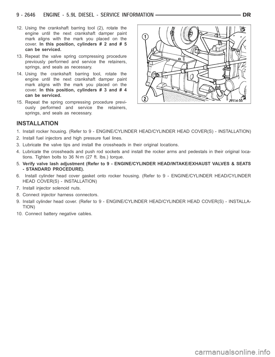
12. Using the crankshaft barring tool (2), rotate the
engine until the next crankshaft damper paint
mark aligns with the mark you placed on the
cover.In this position, cylinders # 2 and # 5
can be serviced.
13. Repeat the valve spring compressing procedure
previously performed and service the retainers,
springs, and seals as necessary.
14. Using the crankshaft barring tool, rotate the
engine until the next crankshaft damper paint
mark aligns with the mark you placed on the
cover.In this position, cylinders # 3 and # 4
can be serviced.
15. Repeat the spring compressing procedure previ-
ously performed and service the retainers,
springs, and seals as necessary.
INSTALLATION
1. Install rocker housing. (Refer to 9 -ENGINE/CYLINDER HEAD/CYLINDER HEAD COVER(S) - INSTALLATION)
2. Install fuel injectors and high pressure fuel lines.
3. Lubricate the valve tips and install the crossheads in their original locations.
4. Lubricate the crossheads and push rod sockets and install the rocker arms and pedestals in their original loca-
tions. Tighten bolts to 36 Nꞏm (27 ft. lbs.) torque.
5.Verify valve lash adjustment (Refer to 9 - ENGINE/CYLINDER HEAD/INTAKE/EXHAUST VALVES & SEATS
- STANDARD PROCEDURE).
6. Install cylinder head cover gasket onto rocker housing. (Refer to 9 - ENGINE/CYLINDER HEAD/CYLINDER
HEAD COVER(S) - INSTALLATION)
7. Install injector solenoid nuts.
8. Connect injector harness connectors.
9. Install cylinder head cover. (Refer to 9 - ENGINE/CYLINDER HEAD/CYLINDER HEAD COVER(S) - INSTALLA-
TION)
10. Connect battery negative cables.
Page 1958 of 5267
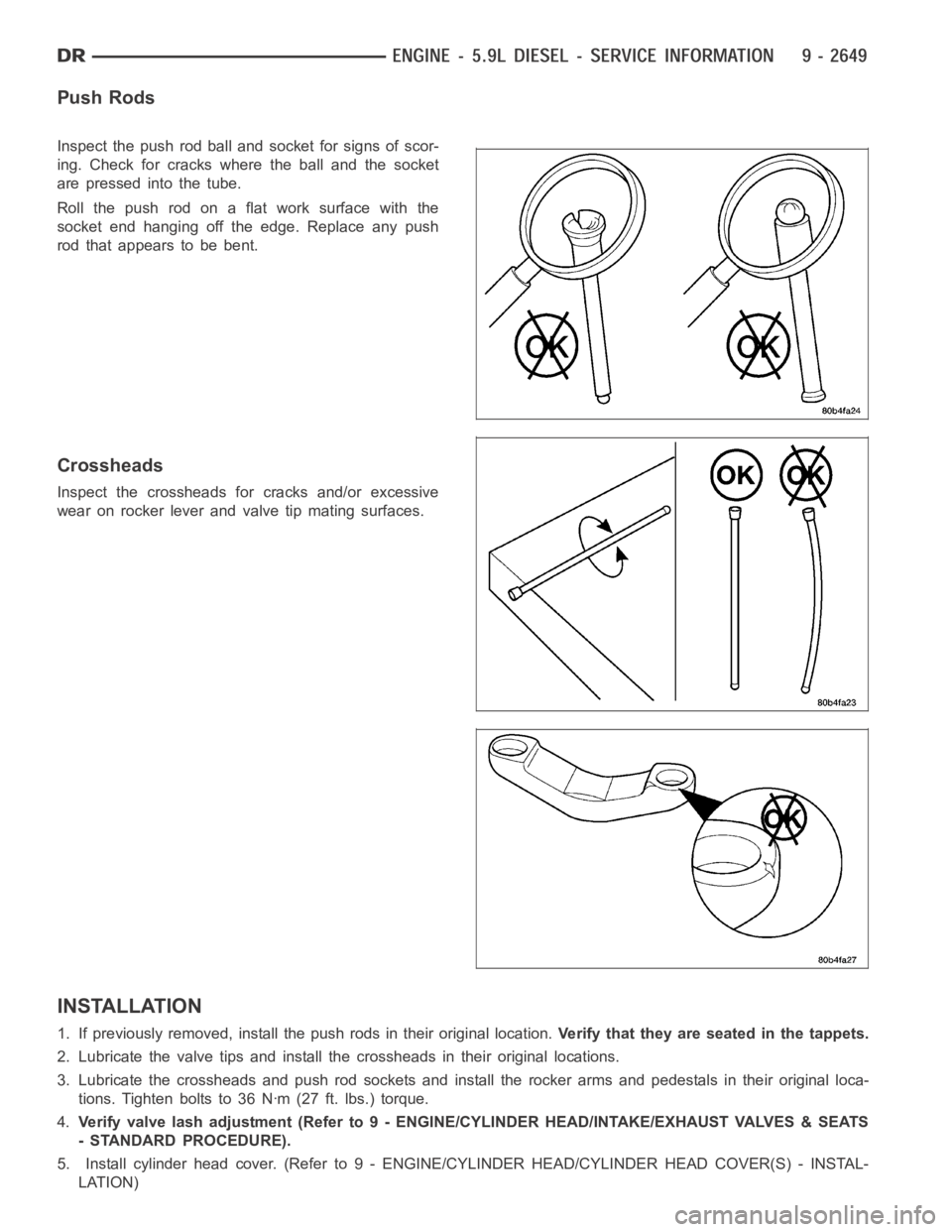
Push Rods
Inspect the push rod ball and socket for signs of scor-
ing. Check for cracks where the ball and the socket
are pressed into the tube.
Roll the push rod on a flat work surface with the
socket end hanging off the edge. Replace any push
rod that appears to be bent.
Crossheads
Inspect the crossheads for cracks and/or excessive
wear on rocker lever and valve tip mating surfaces.
INSTALLATION
1. If previously removed, install the push rods in their original location.Verify that they are seated in the tappets.
2. Lubricate the valve tips and install the crossheads in their original locations.
3. Lubricate the crossheads and push rod sockets and install the rocker arms and pedestals in their original loca-
tions. Tighten bolts to 36 Nꞏm (27 ft. lbs.) torque.
4.Verify valve lash adjustment (Refer to 9 - ENGINE/CYLINDER HEAD/INTAKE/EXHAUST VALVES & SEATS
- STANDARD PROCEDURE).
5. Install cylinder head cover. (Refer to 9 - ENGINE/CYLINDER HEAD/CYLINDER HEAD COVER(S) - INSTAL-
LATION)
Page 1970 of 5267
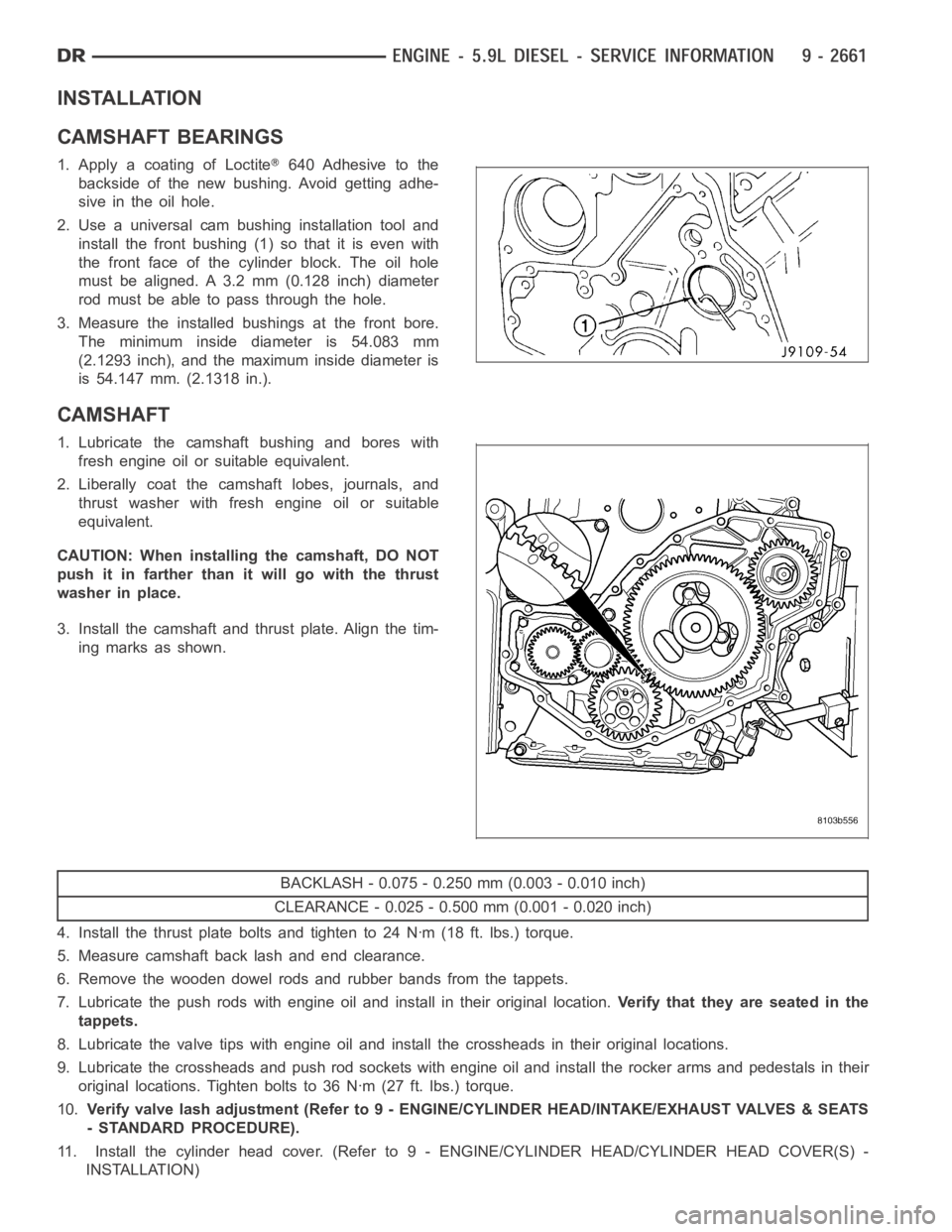
INSTALLATION
CAMSHAFT BEARINGS
1. Apply a coating of Loctite640 Adhesive to the
backside of the new bushing. Avoid getting adhe-
sive in the oil hole.
2. Use a universal cam bushing installation tool and
install the front bushing (1) so that it is even with
the front face of the cylinder block. The oil hole
must be aligned. A 3.2 mm (0.128 inch) diameter
rod must be able to pass through the hole.
3. Measure the installed bushings at the front bore.
The minimum inside diameter is 54.083 mm
(2.1293 inch), and the maximum inside diameter is
is 54.147 mm. (2.1318 in.).
CAMSHAFT
1. Lubricate the camshaft bushing and bores with
fresh engine oil or suitable equivalent.
2. Liberally coat the camshaft lobes, journals, and
thrust washer with fresh engine oil or suitable
equivalent.
CAUTION: When installing the camshaft, DO NOT
push it in farther than it will go with the thrust
washer in place.
3. Install the camshaft and thrust plate. Align the tim-
ing marks as shown.
BACKLASH - 0.075 - 0.250 mm (0.003 - 0.010 inch)
CLEARANCE - 0.025 - 0.500 mm (0.001 - 0.020 inch)
4. Install the thrust plate bolts and tighten to 24 Nꞏm (18 ft. lbs.) torque.
5. Measure camshaft back lash and end clearance.
6. Remove the wooden dowel rods and rubber bands from the tappets.
7. Lubricate the push rods with engine oil and install in their original location.Verify that they are seated in the
tappets.
8. Lubricate the valve tips with engine oil and install the crossheads in their original locations.
9. Lubricate the crossheads and push rod sockets with engine oil and install the rocker arms and pedestals in their
original locations. Tighten bolts to 36 Nꞏm (27 ft. lbs.) torque.
10.Verify valve lash adjustment (Refer to 9 - ENGINE/CYLINDER HEAD/INTAKE/EXHAUST VALVES & SEATS
- STANDARD PROCEDURE).
11. Install the cylinder head cover. (Refer to 9 - ENGINE/CYLINDER HEAD/CYLINDER HEAD COVER(S) -
INSTALLATION)
Page 2146 of 5267
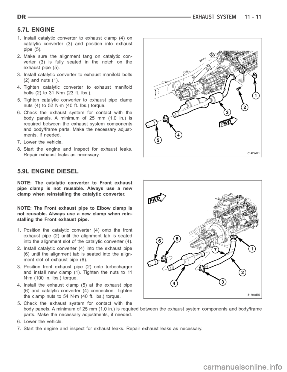
5.7L ENGINE
1. Install catalytic converter to exhaust clamp (4) on
catalytic converter (3) and position into exhaust
pipe (5).
2. Make sure the alignment tang on catalytic con-
verter (3) is fully seated in the notch on the
exhaust pipe (5).
3. Install catalytic converter to exhaust manifold bolts
(2) and nuts (1).
4. Tighten catalytic converter to exhaust manifold
bolts(2)to31Nꞏm(23ft.lbs.).
5. Tighten catalytic converter to exhaust pipe clamp
nuts (4) to 52 Nꞏm (40 ft. lbs.) torque.
6. Check the exhaust system for contact with the
body panels. A minimum of 25 mm (1.0 in.) is
required between the exhaust system components
and body/frame parts. Make the necessary adjust-
ments, if needed.
7. Lower the vehicle.
8. Start the engine and inspect for exhaust leaks.
Repair exhaust leaks as necessary.
5.9L ENGINE DIESEL
NOTE: The catalytic converter to Front exhaust
pipe clamp is not reusable. Always use a new
clamp when reinstalling the catalytic converter.
NOTE: The Front exhaust pipe to Elbow clamp is
not reusable. Always use a new clamp when rein-
stalling the Front exhaust pipe.
1. Position the catalytic converter (4) onto the front
exhaust pipe (2) until the alignment tab is seated
into the alignment slot of the catalytic converter (4).
2. Install catalytic converter (4) into the exhaust pipe
(6) until the alignment tab is seated into the align-
ment slot of exhaust pipe (6).
3. Position front exhaust pipe (2) onto turbocharger
and install new clamp (1). Tighten the nuts to 11
Nꞏm (100 in. lbs.) torque.
4. Install the exhaust clamp (5) at the exhaust pipe
(6) and catalytic converter (4) connection. Tighten
the clamp nuts to 54 Nꞏm (40 ft. lbs.) torque.
5. Check the exhaust system for contact with the
body panels. A minimum of 25 mm (1.0 in.) is required between the exhaust system components and body/frame
parts. Make the necessary adjustments, if needed.
6. Lower the vehicle.
7. Start the engine and inspect for exhaust leaks. Repair exhaust leaks as necessary.
Page 2147 of 5267
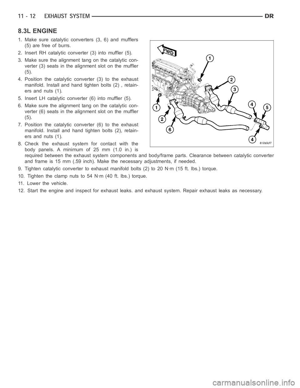
8.3L ENGINE
1. Make sure catalytic converters (3, 6) and mufflers
(5) are free of burrs.
2. Insert RH catalytic converter (3) into muffler (5).
3. Make sure the alignment tang on the catalytic con-
verter (3) seats in the alignment slot on the muffler
(5).
4. Position the catalytic converter (3) to the exhaust
manifold. Install and hand tighten bolts (2) , retain-
ers and nuts (1).
5. Insert LH catalytic converter (6) into muffler (5).
6. Make sure the alignment tang on the catalytic con-
verter (6) seats in the alignment slot on the muffler
(5).
7. Position the catalytic converter (6) to the exhaust
manifold. Install and hand tighten bolts (2), retain-
ers and nuts (1).
8. Check the exhaust system for contact with the
body panels. A minimum of 25 mm (1.0 in.) is
required between the exhaust system components and body/frame parts. Clearance between catalytic converter
and frame is 15 mm (.59 inch). Make the necessary adjustments, if needed.
9. Tighten catalytic converter to exhaust manifold bolts (2) to 20 Nꞏm (15 ft. lbs.) torque.
10. Tighten the clamp nuts to 54 Nꞏm (40 ft. lbs.) torque.
11. Lower the vehicle.
12. Start the engine and inspect for exhaust leaks. and exhaust system. Repair exhaust leaks as necessary.