Page 2202 of 5267
5. Raise and support the frame so the tires are off
floor.
6. Remove the shock absorbers (3) (Refer to 2 -
SUSPENSION/REAR/SHOCK - REMOVAL).
Page 2205 of 5267
24. Lift the axle into position and install the rear
shackle bolts (6).
25. Tighten the bolts to 163 Nꞏm (120 ft. lbs.).
26. Install the lower shock absorber bolts (Refer to 2 -
SUSPENSION/REAR/SHOCK - INSTALLATION).
27. Install the trailer hitch (1) (Refer to 13 - FRAME &
BUMPERS/FRAME/TRAILER HITCH -
INSTALLATION).
Page 2406 of 5267
STEERING
TABLE OF CONTENTS
page page
STEERING
DESCRIPTION ................................. 2
OPERATION ................................... 2
DIAGNOSIS AND TESTING
POWER STEERING SYSTEM ................. 2
POWER STEERING FLOW AND PRESSURE . . . 4
SPECIAL TOOLS
STEERING .................................. 6COLUMN...............................7
GEAR - INDEPENDENT FRONT SUSPENSION..38
GEAR - LINK/COIL.......................43
LINKAGE - INDEPENDENT FRONT
SUSPENSION...........................62
LINKAGE - LINK/COIL....................66
PUMP.................................76
PUMP - SRT10..........................92
Page 2408 of 5267

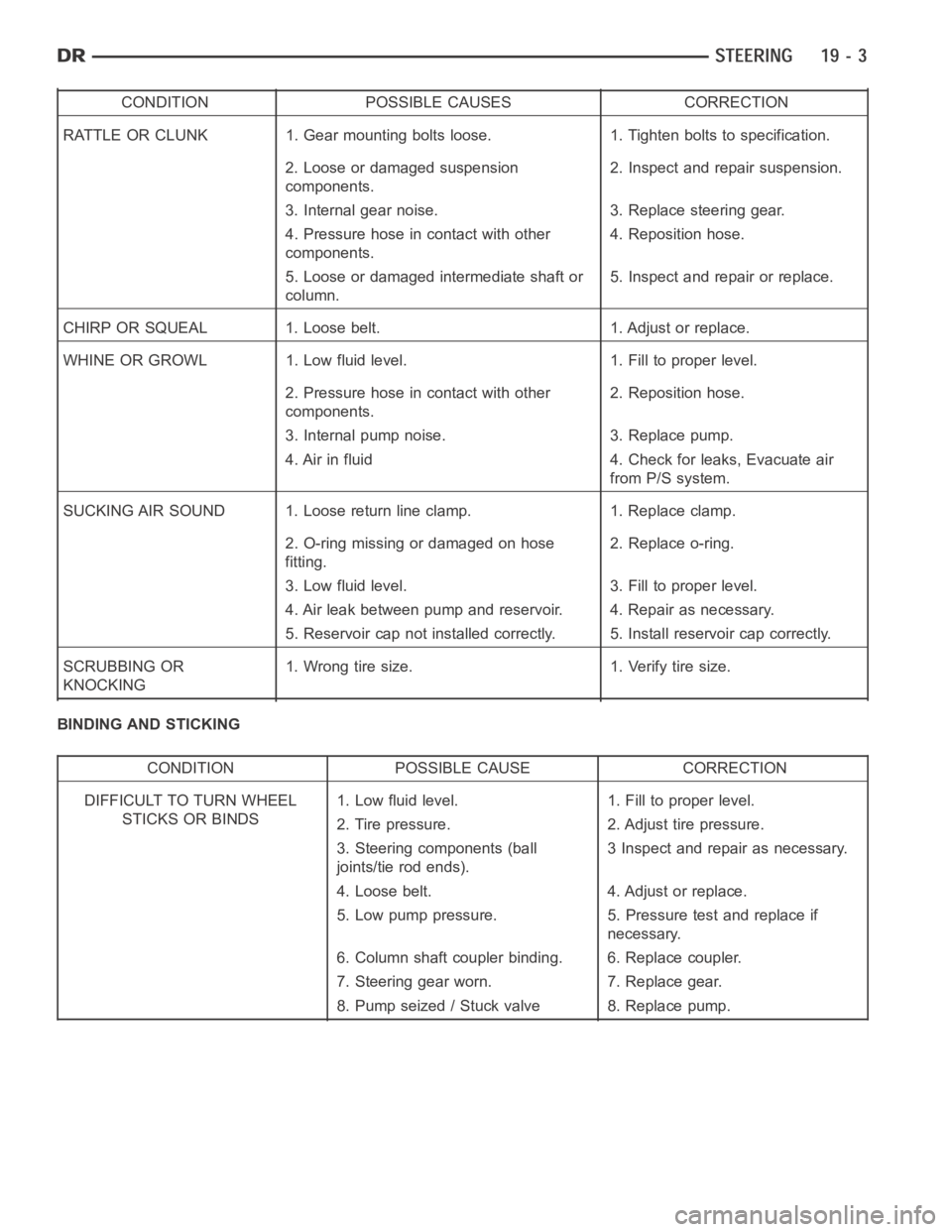
CONDITION POSSIBLE CAUSES CORRECTION
RATTLE OR CLUNK 1. Gear mounting bolts loose. 1. Tighten bolts to specification.
2. Loose or damaged suspension
components.2. Inspect and repair suspension.
3. Internal gear noise. 3. Replace steering gear.
4. Pressure hose in contact with other
components.4. Reposition hose.
5. Loose or damaged intermediate shaft or
column.5. Inspect and repair or replace.
CHIRP OR SQUEAL 1. Loose belt. 1. Adjust or replace.
WHINE OR GROWL 1. Low fluid level. 1. Fill to proper level.
2. Pressure hose in contact with other
components.2. Reposition hose.
3. Internal pump noise. 3. Replace pump.
4. Air in fluid 4. Check for leaks, Evacuate air
from P/S system.
SUCKING AIR SOUND 1. Loose return line clamp. 1. Replace clamp.
2. O-ring missing or damaged on hose
fitting.2. Replace o-ring.
3. Low fluid level. 3. Fill to proper level.
4. Air leak between pump and reservoir. 4. Repair as necessary.
5. Reservoir cap not installed correctly. 5. Install reservoir cap correctly.
SCRUBBING OR
KNOCKING1. Wrong tire size. 1. Verify tire size.
BINDING AND STICKING
CONDITION POSSIBLE CAUSE CORRECTION
DIFFICULT TO TURN WHEEL
STICKS OR BINDS1. Low fluid level. 1. Fill to proper level.
2. Tire pressure. 2. Adjust tire pressure.
3. Steering components (ball
joints/tie rod ends).3 Inspect and repair as necessary.
4. Loose belt. 4. Adjust or replace.
5. Low pump pressure. 5. Pressure test and replace if
necessary.
6. Column shaft coupler binding. 6. Replace coupler.
7. Steering gear worn. 7. Replace gear.
8. Pump seized / Stuck valve 8. Replace pump.
Page 2409 of 5267

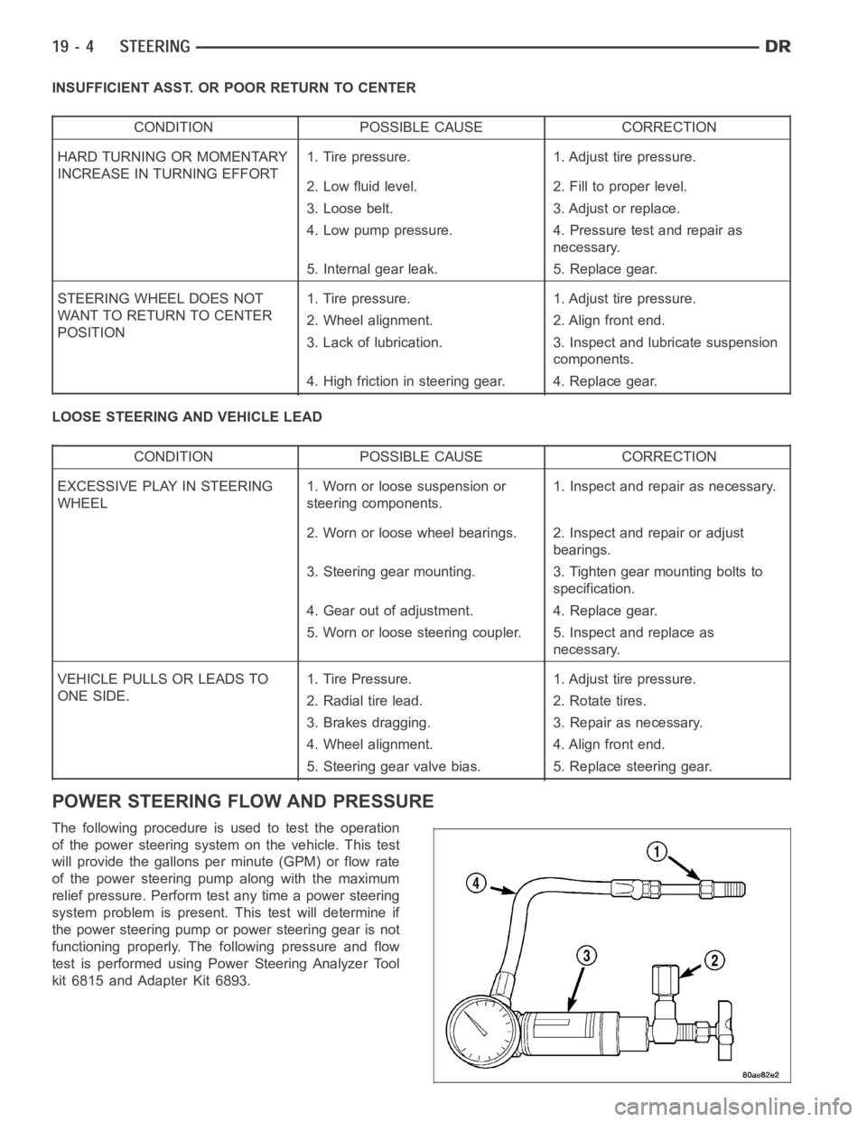
INSUFFICIENT ASST. OR POOR RETURN TO CENTER
CONDITION POSSIBLE CAUSE CORRECTION
HARD TURNING OR MOMENTARY
INCREASE IN TURNING EFFORT1. Tire pressure. 1. Adjust tire pressure.
2. Low fluid level. 2. Fill to proper level.
3. Loose belt. 3. Adjust or replace.
4. Low pump pressure. 4. Pressure test and repair as
necessary.
5. Internal gear leak. 5. Replace gear.
STEERING WHEEL DOES NOT
WANT TO RETURN TO CENTER
POSITION1. Tire pressure. 1. Adjust tire pressure.
2. Wheel alignment. 2. Align front end.
3. Lack of lubrication. 3. Inspect and lubricate suspension
components.
4. High friction in steering gear. 4. Replace gear.
LOOSE STEERING AND VEHICLE LEAD
CONDITION POSSIBLE CAUSE CORRECTION
EXCESSIVE PLAY IN STEERING
WHEEL1. Worn or loose suspension or
steering components.1. Inspect and repair as necessary.
2. Worn or loose wheel bearings. 2. Inspect and repair or adjust
bearings.
3. Steering gear mounting. 3. Tighten gear mounting bolts to
specification.
4. Gear out of adjustment. 4. Replace gear.
5. Worn or loose steering coupler. 5. Inspect and replace as
necessary.
VEHICLE PULLS OR LEADS TO
ONE SIDE.1. Tire Pressure. 1. Adjust tire pressure.
2. Radial tire lead. 2. Rotate tires.
3. Brakes dragging. 3. Repair as necessary.
4. Wheel alignment. 4. Align front end.
5. Steering gear valve bias. 5. Replace steering gear.
POWER STEERING FLOW AND PRESSURE
The following procedure is used to test the operation
of the power steering system on the vehicle. This test
will provide the gallons per minute (GPM) or flow rate
of the power steering pump along with the maximum
relief pressure. Perform test any time a power steering
system problem is present. This test will determine if
the power steering pump or power steering gear is not
functioning properly. The following pressure and flow
test is performed using Power Steering Analyzer Tool
kit 6815 and Adapter Kit 6893.
Page 2443 of 5267
page page
GEAR - INDEPENDENT FRONT SUSPENSION
DESCRIPTION ................................ 39
REMOVAL .................................... 39
INSTALLATION ............................... 40
SPECIFICATIONS
TORQUE ................................... 41BUSHING
REMOVAL .................................... 42
INSTALLATION ............................... 42
Page 2444 of 5267

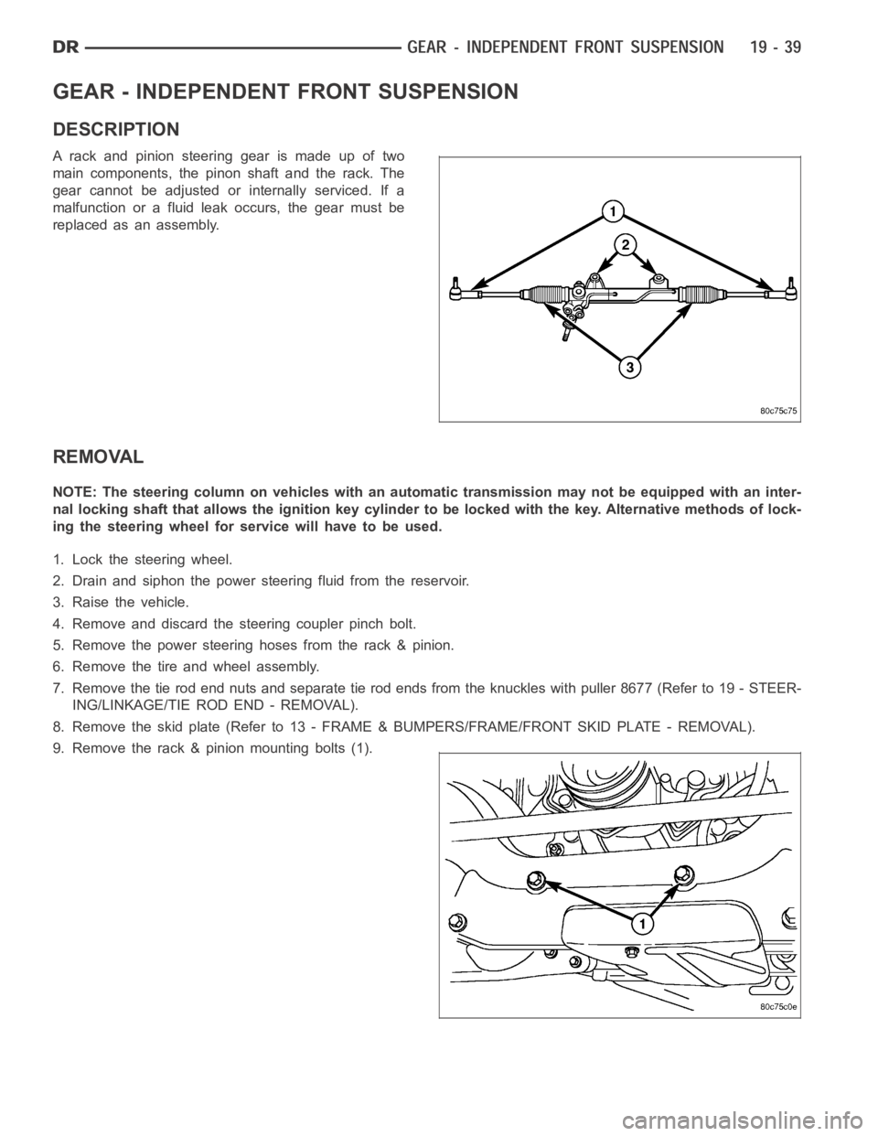
GEAR - INDEPENDENT FRONT SUSPENSION
DESCRIPTION
A rack and pinion steering gear is made up of two
main components, the pinon shaft and the rack. The
gear cannot be adjusted or internally serviced. If a
malfunction or a fluid leak occurs, the gear must be
replaced as an assembly.
REMOVAL
NOTE: The steering column on vehicles with an automatic transmission may not be equipped with an inter-
nal locking shaft that allows the ignition key cylinder to be locked with the key. Alternative methods of lock-
ing the steering wheel for service will have to be used.
1. Lock the steering wheel.
2. Drain and siphon the power steering fluid from the reservoir.
3. Raise the vehicle.
4. Remove and discard the steering coupler pinch bolt.
5. Remove the power steering hoses from the rack & pinion.
6. Remove the tire and wheel assembly.
7. Remove the tie rod end nuts and separate tie rod ends from the knuckles withpuller8677(Referto19-STEER-
ING/LINKAGE/TIE ROD END - REMOVAL).
8. Remove the skid plate (Refer to 13 - FRAME & BUMPERS/FRAME/FRONT SKID PLATE - REMOVAL).
9. Remove the rack & pinion mounting bolts (1).
Page 2445 of 5267

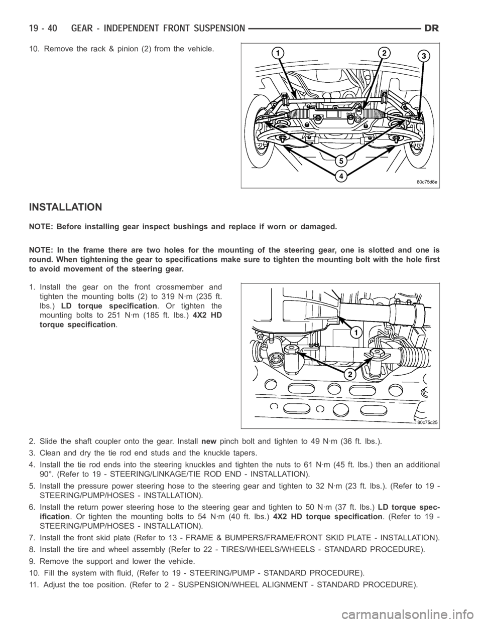
10. Remove the rack & pinion (2) from the vehicle.
INSTALLATION
NOTE: Before installing gear inspect bushings and replace if worn or damaged.
NOTE: In the frame there are two holes for the mounting of the steering gear,oneisslottedandoneis
round. When tightening the gear to specificationsmakesuretotightenthemounting bolt with the hole first
to avoid movement of the steering gear.
1. Install the gear on the front crossmember and
tighten the mounting bolts (2) to 319 Nꞏm (235 ft.
lbs.)LD torque specification.Ortightenthe
mounting bolts to 251 Nꞏm (185 ft. lbs.)4X2 HD
torque specification.
2. Slide the shaft coupler onto the gear. Installnewpinch bolt and tighten to 49 Nꞏm (36 ft. lbs.).
3. Clean and dry the tie rod end studs and the knuckle tapers.
4. Install the tie rod ends into the steering knuckles and tighten the nuts to61Nꞏm(45ft.lbs.)thenanadditional
90°. (Refer to 19 - STEERING/LINKAGE/TIE ROD END - INSTALLATION).
5. Install the pressure power steering hose to the steering gear and tightento32Nꞏm(23ft.lbs.).(Referto19-
STEERING/PUMP/HOSES - INSTALLATION).
6. Install the return power steering hose to the steering gear and tighten to50Nꞏm(37ft.lbs.)LD torque spec-
ification. Or tighten the mounting bolts to 54 Nꞏm (40 ft. lbs.)4X2 HD torque specification.(Referto19-
STEERING/PUMP/HOSES - INSTALLATION).
7. Install the front skid plate (Refer to 13 - FRAME & BUMPERS/FRAME/FRONT SKID PLATE - INSTALLATION).
8. Install the tire and wheel assembly (Refer to 22 - TIRES/WHEELS/WHEELS -STANDARD PROCEDURE).
9. Remove the support and lower the vehicle.
10. Fill the system with fluid, (Refer to 19 - STEERING/PUMP - STANDARD PROCEDURE).
11. Adjust the toe position. (Refer to 2 - SUSPENSION/WHEEL ALIGNMENT - STANDARD PROCEDURE).