2006 DODGE RAM SRT-10 water pump
[x] Cancel search: water pumpPage 310 of 5267

When Monitored:
Ignition on, Engine running, and no ECT DTCs present.
Set Condition:
PCM recognizes that the ECT has failed its self coherence test. The coolanttemp should only change at a
certain rate, if this rate is too slow or too fast this fault will set. Two trip fault. Three good trips to clear MIL.
ETC light will illuminate on first trip failure.
Possible Causes
LOW COOLANT LEVEL
(K2) ECT SIGNAL CIRCUIT SHORTED TO BATTERY VOLTAGE
(K2) ECT SIGNAL CIRCUIT OPEN
(K900) SENSOR GROUND CIRCUIT OPEN
(K2) ECT SIGNAL CIRCUIT SHORTED TO GROUND
(K2) ECT SIGNAL CIRCUIT SHORTED TO THE (K900) SENSOR GROUND
THERMOSTAT
ECT SENSOR
PCM
Always perform the Pre-Diagnostic Troubleshooting procedure before proceeding. (Refer to 9 - ENGINE -
DIAGNOSIS AND TESTING).
Diagnostic Test
1.ACTIVE DTC
Ignition on, engine not running.
NOTE: If this code sets during extreme ambient temperatures, improper installation of a block heater could
be the cause of this DTC.
With a scan tool, read DTCs.
Diagnose all other ECT and Cooling System codes before continuing.
Is the DTC active at this time?
Ye s>>
Go To 2
No>>
Refer to the INTERMITTENT CONDITION Diagnostic Procedure.
Perform the POWERTRAIN VERIFICATION TEST. (Refer to 9 - ENGINE - STANDARD PROCEDURE)
2.LOW COOLANT LEVEL
NOTE: If a Engine Coolant Temperature (ECT) DTC is set along with this code,diagnose the ECT DTC first.
NOTE: Inspect the ECT terminals and related PCM terminals. Ensure the terminals are free from corrosion
and damage.
NOTE: The best way to diagnose this DTC is to allow the vehicle to sit overnight outside in order to have
a totally cold soaked engine.
NOTE: Extremely cold outside ambient temperatures may have caused this DTCtoset.
NOTE: Need to make sure that no Cooling System DTCs are set or changes that would make the warm up
much slower or much faster: broken water pump can set this, addition of aftermarket auxiliary cooler can
set this DTC.
WARNING: Never open the cooling system when the engine is hot. The system isunder pressure. Failure to
follow these instructions can result in personal injury or death. Allow the engine to cool before opening the
cooling system.
Page 435 of 5267

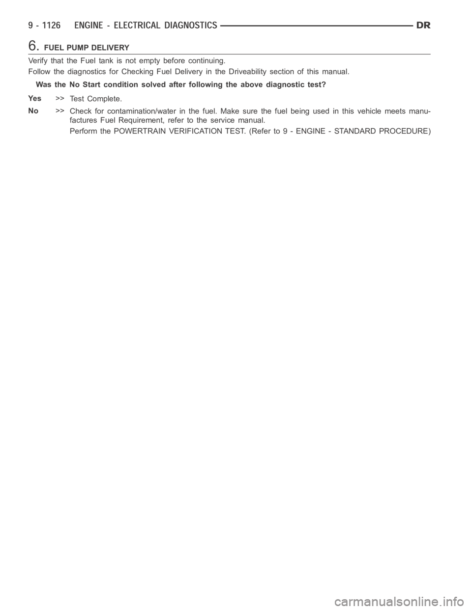
6.FUEL PUMP DELIVERY
Verify that the Fuel tank is not empty before continuing.
Follow the diagnostics for CheckingFuel Delivery in the Driveability section of this manual.
Was the No Start condition solved after following the above diagnostic test?
Ye s>>
Te s t C o m p l e t e .
No>>
Check for contamination/water in the fuel. Make sure the fuel being used inthis vehicle meets manu-
factures Fuel Requirement, refer to the service manual.
Perform the POWERTRAIN VERIFICATION TEST. (Refer to 9 - ENGINE - STANDARD PROCEDURE)
Page 450 of 5267

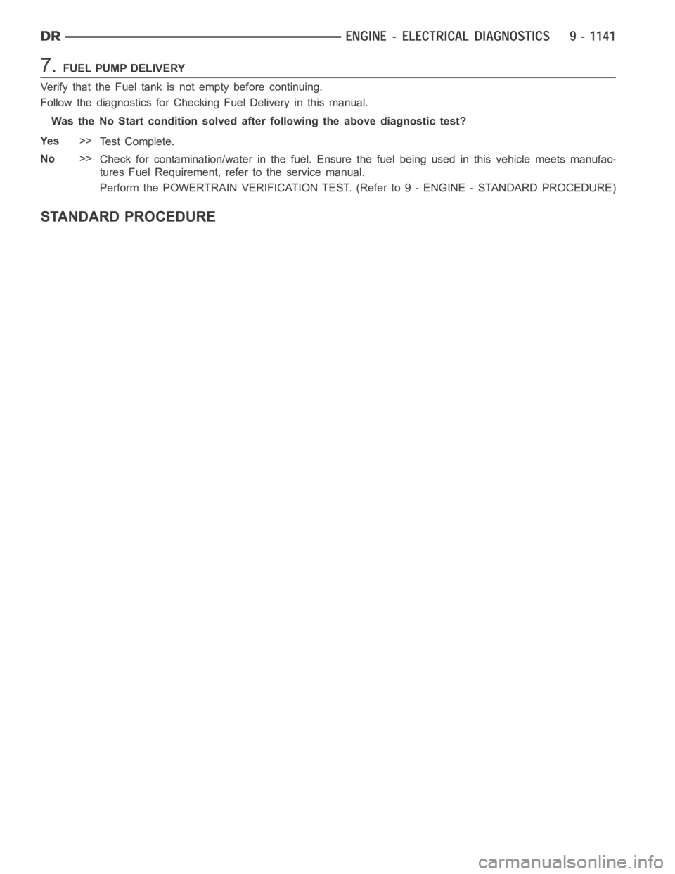
7.FUEL PUMP DELIVERY
Verify that the Fuel tank is not empty before continuing.
Follow the diagnostics for Checking Fuel Delivery in this manual.
Was the No Start condition solved after following the above diagnostic test?
Ye s>>
Te s t C o m p l e t e .
No>>
Check for contamination/water in the fuel. Ensure the fuel being used in this vehicle meets manufac-
tures Fuel Requirement, refer to the service manual.
Perform the POWERTRAIN VERIFICATION TEST. (Refer to 9 - ENGINE - STANDARD PROCEDURE)
STANDARD PROCEDURE
Page 455 of 5267

page page
ENGINE - ELECTRICAL DIAGNOSTICS -
DIESEL
DIAGNOSIS AND TESTING
PRE-DIAGNOSTIC TROUBLESHOOTING
PROCEDURE............................. 1150
POWERTRAIN VERIFICATION TEST VER - 1
(DIESEL)................................. 1152
POWERTRAIN VERIFICATION TEST VER - 2
(DIESEL)................................. 1153
POWERTRAIN VERIFICATION TEST VER - 4
(DIESEL)................................. 1154
POWERTRAIN VERIFICATION TEST VER - 5
(DIESEL)................................. 1156
INTERMITTENT CONDITION ............... 1157
P0016-ENGINE SPEED SIGNAL MISMATCH . 1158
P0069-BOOST KEY ON RATIONALITY ...... 1160
P0071-INLET AIR TEMP SENSOR
RATIONALITY............................ 1163
P0072-INLET AIR TEMP SENSOR VOLTAGE
TOO LOW................................ 1165
P0073-INLET AIR TEMP SENSOR VOLTAGE
TOO HIGH............................... 1169
P0088-FUEL RAIL PRESSURE SIGNAL IS
ABOVE MAX LIMIT........................ 1174
P0106-INLET AIR PRESSURE SENSOR
RATIONALITY............................ 1176
P0107-INLET AIR PRESSURE SENSOR
VOLTAGE TOO LOW...................... 1178
P0108-INLET AIR PRESSURE SENSOR
VOLTAGE TOO HIGH...................... 1183
P0111-INTAKE AIR TEMPERATURE (IAT)
SENSOR RATIONALITY................... 1188
P0112-INTAKE AIR TEMPERATURE (IAT)
SENSOR VOLTAGE TOO LOW............. 1190
P0113-INTAKE AIR TEMPERATURE (IAT)
SENSOR VOLTAGE TOO HIGH............. 1195
P0116-ENGINE COOLANT TEMPERATURE
(ECT) SENSOR RATIONALITY............. 1200
P0117-ENGINE COOLANT TEMPERATURE
(ECT) SENSOR VOLTAGE TOO LOW....... 1202
P0118-ENGINE COOLANT TEMPERATURE
(ECT) SENSOR VOLTAGE TOO HIGH...... 1206
P0128-THERMOSTAT RATIONALITY ........ 1211
P0148-HIGH PRESSURE COMMON RAIL
(HPCR) CHECKSUM...................... 1212
P0169-WATER IN FUEL (WIF) LIGHT ON
TOO LONG............................... 1215
P0191-FUEL RAIL PRESSURE SENSOR
PERFORMANCE.......................... 1217
P0192-FUEL PRESSURE SENSOR
VOLTAGE TOO LOW...................... 1219P0193-FUEL PRESSURE SENSOR
VOLTAGE TOO HIGH...................... 1224
P0201-INJECTOR #1 CONTROL CIRCUIT . . . 1229
P0202-INJECTOR #2 CONTROL CIRCUIT . . . 1233
P0203-INJECTOR #3 CONTROL CIRCUIT . . . 1237
P0204-INJECTOR #4 CONTROL CIRCUIT . . . 1241
P0205-INJECTOR #5 CONTROL CIRCUIT . . . 1245
P0206-INJECTOR #6 CONTROL CIRCUIT . . . 1249
P0217-DECREASED ENGINE
PERFORMANCE DUE TO ENGINE
OVERHEAT CONDITION................... 1253
P0219-CRANKSHAFT POSITION SENSOR
OVER SPEED SIGNAL.................... 1255
P0234-TURBOCHARGER OVERBOOST
CONDITION.............................. 1257
P0236-MAP SENSOR TOO HIGH
TOO LONG............................... 1259
P0237-MAP SENSOR VOLTAGE TOO LOW . 1261
P0238-MAP SENSOR VOLTAGE TOO HIGH . 1266
P0243-WASTEGATE PRESSURE CONTROL
PWM.................................... 1271
P0251-CP3 PUMP REGULATOR CONTROL . 1277
P0299-BOOST IN RANGE LOW ............ 1283
P0300-MULTIPLE CYLINDER MISFIRE ..... 1286
P0301-CYLINDER # 1 MISFIRE ............ 1289
P0302-CYLINDER # 2 MISFIRE ............ 1292
P0303-CYLINDER # 3 MISFIRE ............ 1295
P0304-CYLINDER # 4 MISFIRE ............ 1298
P0305-CYLINDER # 5 MISFIRE ............ 1301
P0306-CYLINDER # 6 MISFIRE ............ 1304
P0335-CRANKSHAFT POSITION (CKP)
LOST.................................... 1307
P0336-CRANKSHAFT POSITION (CKP)
SENSOR SIGNAL......................... 1313
P0337-CRANKSHAFT POSITION (CKP)
SENSOR VOLTAGE TOO LOW............. 1319
P0338-CRANKSHAFT POSITION (CKP)
SENSOR VOLTAGE TOO HIGH............ 1322
P0340-CAMSHAFT POSITION (CMP) LOST . 1324
P0341-CAMSHAFT POSITION (CMP)
SENSOR SIGNAL......................... 1330
P0381-WAIT TO START LAMP
INOPERATIVE............................ 1336
P0461-FUEL LEVEL UNIT NO CHANGE
OVER TIME.............................. 1338
P0462-LOW VOLTAGE DETECTED AT THE
FUEL LEVEL SENSOR.................... 1341
P0463-HIGH VOLTAGE DETECTED AT THE
FUEL LEVEL SENSOR.................... 1345
P0477-LOW VOLTAGE ON THE ENGINE
BRAKE DRIVER.......................... 1348
Page 456 of 5267

P0478-HIGH VOLTAGE ON THE ENGINE
BRAKE DRIVER.......................... 1350
P0480-FAN CLUTCH ...................... 1352
P0483-FAN SPEED ....................... 1357
P0500-NO VEHICLE SPEED SENSOR
SIGNAL.................................. 1364
P0513-SKIM INVALID KEY ERROR ......... 1368
P0514-BAT TEMPERATURE SENSOR
RATIONALITY............................ 1370
P0516-LOW VOLTAGE AT THE BAT TEMP
SENSOR................................. 1372
P0517-HIGH VOLTAGE AT THE BAT TEMP
SENSOR................................. 1376
P0521-OIL PRESSURE SWITCH
RATIONALITY............................ 1380
P0524-OIL PRESSURE TOO LOW .......... 1383
P0532-A/C SENDING UNIT VOLTS TOO
LOW..................................... 1385
P0533-A/C SENDING UNIT VOLTS TOO
HIGH.................................... 1391
P0541-LOW VOLTAGE ON THE #1 INTAKE
AIR HEATER RELAY...................... 1396
P0542-HIGH VOLTAGE ON THE #1 INTAKE
AIR HEATER RELAY...................... 1399
P0562-BATTERY VOLTAGE LOW ........... 1402
P0563-BATTERY VOLTAGE HIGH .......... 1406
P0572-LOW VOLTAGE DETECTED AT THE
BRAKE SWITCH.......................... 1409
P0573-HIGH VOLTAGE DETECTED AT THE
BRAKE SWITCH.......................... 1413
P0580-LOW VOLTAGE DETECTED AT THE
SPEED CONTROL SWITCH................ 1416
P0581-HIGH VOLTAGE DETECTED AT THE
SPEED CONTROL SWITCH................ 1420
P0602-CHECKSUM ERROR ............... 1425
P0604-ECM SOFTWARE ERROR .......... 1426
P0606-ECM HARDWARE ERROR .......... 1427
P0607-ECM INTERNAL FAILURE ........... 1428
P0622-GENERATOR FIELD NOT
SWITCHING PROPERLY.................. 1429
P0628-LOW VOLTAGE DETECTED AT THE
FUEL LIFT PUMP......................... 1433
P0629-HIGH VOLTAGE DETECTED AT THE
FUEL LIFT PUMP......................... 1436
P0630-VIN NOT ENTERED ERROR ........ 1439
P0633-SKIM SECRET KEY NOT ENTERED . 1440
P0642-LOW VOLTAGE AT THE #2 SENSOR
SUPPLY CIRCUIT......................... 1441
P0643-HIGH VOLTAGE AT THE #2 SENSOR
SUPPLY CIRCUIT......................... 1445
P0646-LOW VOLTAGE DETECTED AT THE
A/C CLUTCH RELAY...................... 1448
P0647-HIGH VOLTAGE DETECTED AT THE
A/C CLUTCH RELAY...................... 1451
P0652-LOW VOLTAGE AT THE #1 SENSOR
SUPPLY CIRCUIT......................... 1454
P0653-HIGH VOLTAGE AT THE #1 SENSOR
SUPPLY CIRCUIT......................... 1458P0698-ACCELERATOR PEDAL POSITION
SENSOR (APPS) SUPPLY VOLTAGE TOO
LOW..................................... 1461
P0699-ACCELERATOR PEDAL POSITION
SENSOR (APPS) SUPPLY VOLTAGE TOO
HIGH.................................... 1465
P1272-A/C CLUTCH CONTROL CIRCUIT 2
LOW..................................... 1468
P1273-A/C CLUTCH CONTROL CIRCUIT 2
HIGH.................................... 1471
P1274-A/C CLUTCH CONTROL CIRCUIT 2
OPEN.................................... 1475
P1275-A/C CLUTCH CONTROL CIRCUIT 2
OVERCURRENT.......................... 1479
P127C-FUEL PUMP CONTROL CIRCUIT 2
LOW..................................... 1482
P127D-FUEL PUMP CONTROL CIRCUIT 2
HIGH.................................... 1485
P127E-FUEL PUMP CONTROL CIRCUIT 2
OPEN (TIPM)............................. 1489
P0127F-FUEL PUMP CONTROL CIRCUIT 2
OVERCURRENT (TIPM)
................... 1493
P1652-J1850 SHORT TO GROUND ......... 1496
P2121-PPS CONFORMANCE ERROR ...... 1499
P2122-PPS 1 VOLTAGE TOO LOW ......... 1511
P2123-PPS 1 VOLTAGE TOO HIGH ........ 1516
P2127-PPS 2 VOLTAGE TOO LOW ......... 1520
P2128-PPS 2 VOLTAGE TOO HIGH ........ 1525
P2146-BANK 1 (CYLINDERS 1-3) SHORTED
HIGH OR LOW........................... 1529
P2149-BANK 2 (CYLINDERS 4-6) SHORTED
HIGH OR LOW........................... 1537
P2266-WATER IN FUEL (WIF) SENSOR
VOLTAGE TOO LOW...................... 1544
P2269-WATER IN FUEL (WIF) .............. 1547
P2502-CHARGING SYSTEM ERROR ....... 1549
P2503-CHARGING SYSTEM OUTPUT LOW . 1552
P2504-CHARGING SYSTEM OUTPUT HIGH . 1555
P2509-POWERDOWN DATA LOST ERROR . 1559
P2607-LOW VOLTAGE AT THE #2 INTAKE
AIR HEATER RELAY...................... 1563
P2608-HIGH VOLTAGE AT THE #2 INTAKE
AIR HEATER RELAY...................... 1566
P2609-NO VOLTAGE DROP SEEN FROM
INTAKE AIR HEATERS.................... 1569
*CHECKING THE ACCELERATOR PEDAL
SENSOR CALIBRATION................... 1572
*CHECKING THE ECM POWER AND
GROUNDS............................... 1573
* PRESSURE LIMITING VALVE TEST ....... 1574
*ENGINE SURGES ........................ 1575
*ENGINE NO START/HARD START ......... 1578
*FUEL HEATER THERMOSTAT TEST ....... 1581
*IN-TANK FUEL LIFT PUMP FLOW/
DIAGNOSTIC TEST PROCEDURE.......... 1582
*FUEL PUMP RETURN FLOW TEST ........ 1585
*HIGH PRESSURE FUEL PUMP
PERFORMANCE TEST.................... 1586
*INJECTOR RETURN FLOW TEST ......... 1587
Page 892 of 5267

1.
1. Using the Scan tool, check for DTCs. Troubleshoot any active DTCs beforeperforming this test.
2. Disconnect the wiring harness from the lift pump at the fuel tank module connector and inspect the pins for
damage. Fix or replace any damaged component.
3. Connect a voltmeter between the fuel lift pump supply and return pins at the fuel tank module connector.
4. Turn the ignition to the on position. Use the Scan tool to actuate the fuellift pump, record the voltage on the
voltmeter.
5. If the voltage is greater than 11.5 volts, go to step 14. If the voltage is lessthan11.5volts,gotostep6
6. Using a voltmeter, measure the battery voltage to determine that the voltage is greater than 11.5 volts. If the
voltage is greater than 11.5 volts, go to step 7. If the voltage is not greater than 11.5 volts, troubleshoot for low
battery voltage.
7. Remove the fuel lift pump relay from the PDC. Use a voltmeter to measure the voltage at the fuel lift pump relay
voltage supply pin in the PDC. If the voltage is greater than 11.5 volts, go to step 8. If the voltage is not greater than
11.5 volts, fix or replace the harness.
8. Remove the fuel lift pump relay from the PDC. Install a spare relay in place of the fuel lift pump relay. Using the
Scan tool, actuate the fuel lift pump. Use a voltmeter to measure the voltage between the fuel lift pump supply and
return pins at the fuel tank module connector while the fuel lift pump is actuated. If the voltage is greater than 11.5
volts, replace the fuel lift pump relay. If the voltage is not greater than 11.5volts,gotostep9.
9. Disconnect the wiring harness from the fuel tank module. Remove the liftpump relay from the PDC. Using an
Ohmmeter, measure the resistance of the fuel lift pump power supply wire between the PDC relay output pin and
the fuel tank module connector. If the resistance is less than 10 ohms, go tostep 10. If it is greater than 10 ohms,
fix or replace the harness.
10. Disconnect the wiring harness from the fuel tank module. Remove the fuel lift pump relay from the PDC. Using
a voltmeter, measure the voltage between battery negative and the fuel lift pump power supply wire at the fuel
module connector. If the voltage is less than 1 volt, go to step 11. If the voltage is greater than 1 volt, fix or replace
the harness.
11. Disconnect the wiring harness from the fuel tank module. Remove the fuel lift pump relay from the PDC. Using
an ohmmeter, measure the resistance between battery negative and the fuellift pump power supply wire at the fuel
module connector. If the resistance is less than 10 ohms, fix or replace theharness. If the resistance is greater than
10 ohms, go to step 12.
12. Disconnect the wiring harness from the fuel tank module. Using an Ohmmeter, measure the resistance of the
fuel lift pump ground wire between the fuel tank module connector and battery negative. If the resistance is less
than 10 ohms, go to step 13. If the resistance is greater than 10 ohms, fix or replace the harness.
13. Disconnect the wiring harness from the fuel tank module. Using a voltmeter, measure the voltage between the
fuel lift pump ground wire and battery negative. If the voltage is less than1 volt, go to step 14. If the voltage is
greater than 1 volt, fix or replace the harness.
14. Reconnect the lift pump connector.
FLOW TEST.
1. Remove the fuel pump supply banjo fitting from the fuel injection pump.
2. Install Miller Tool #9014 fuel system test fitting into the fuel injection pump.
3. Connect one end of a section of fuel hose to the test fitting.
4. Put the other end of the fuel hose into an empty fuel container.
5. Use the scan tool to actuate the fuel lift pump.
6. While the lift pump is running, move the fuel hose from the fuel canister into a 1000ml graduated cylinder for 10
seconds.
7. Read and record the amount of fuel in the graduated cylinder after 10 seconds.
8. If you have more than 430ml in the graduated cylinder after 10 seconds, the test has successfully passed.
9. If you have less than 430ml of fuel in the graduated cylinder, inspect thefuel supply line from the fuel tank to the
fuel filter housing and the fuel supply line between the fuel filter housing and the high pressure fuel pump for signs
of damage, replace as necessary. If no damage is found, replace the fuel filter and retest.
10.Verify the Screened Banjo Bolt at the outlet of the fuel filter is free ofdebris. If debris is found, rinse screen with
water, blow dry and reinstall. Retest vehicle. If flow meets specification then trace back the source of debris, if flow
is still below spec repair damaged component.
Page 895 of 5267

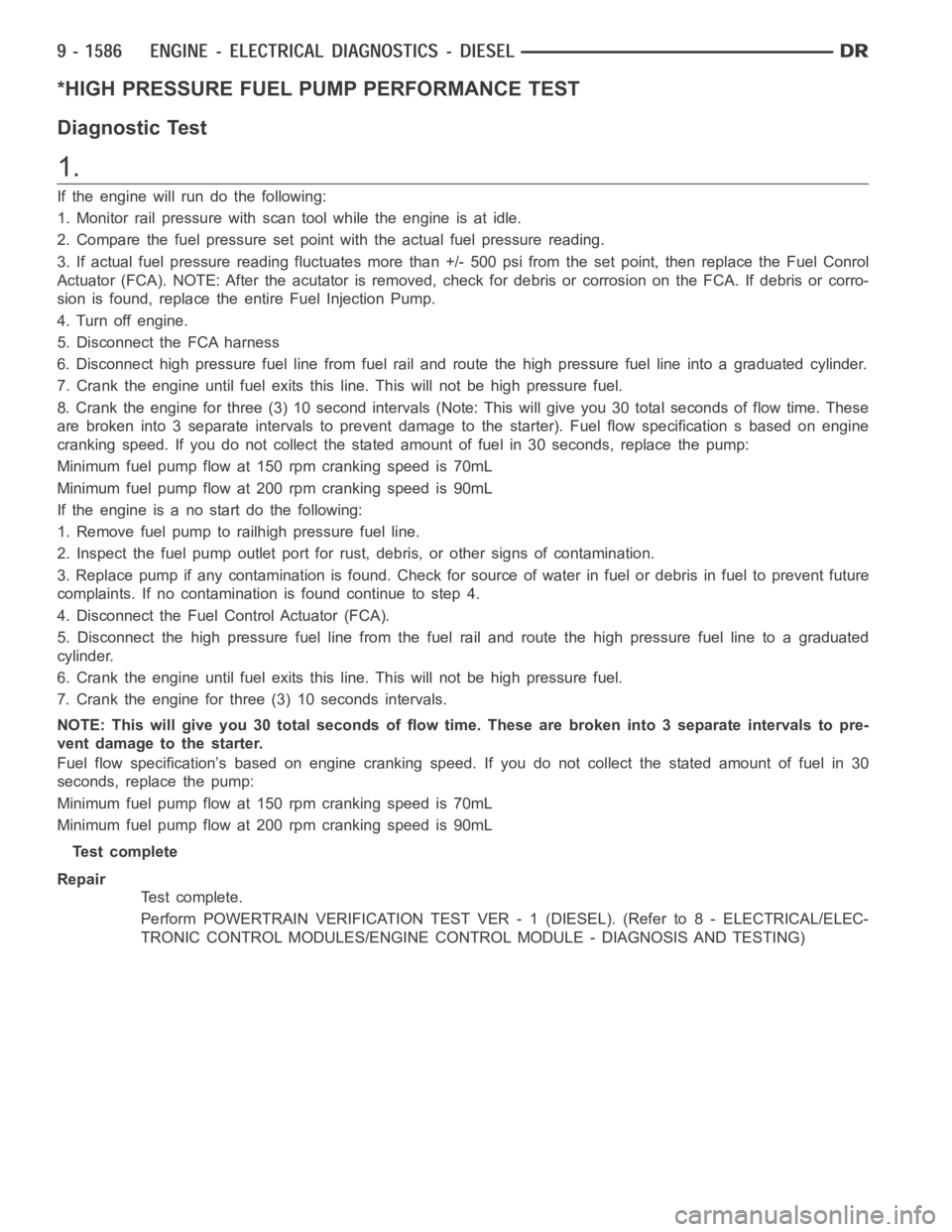
*HIGH PRESSURE FUEL PUMP PERFORMANCE TEST
Diagnostic Test
1.
If the engine will run do the following:
1. Monitor rail pressure with scan tool while the engine is at idle.
2. Compare the fuel pressure set point with the actual fuel pressure reading.
3. If actual fuel pressure reading fluctuates more than +/- 500 psi from theset point, then replace the Fuel Conrol
Actuator (FCA). NOTE: After the acutator is removed, check for debris or corrosion on the FCA. If debris or corro-
sion is found, replace the entire Fuel Injection Pump.
4. Turn off engine.
5. Disconnect the FCA harness
6. Disconnect high pressure fuel line from fuel rail and route the high pressure fuel line into a graduated cylinder.
7. Crank the engine until fuel exits this line. This will not be high pressurefuel.
8. Crank the engine for three (3) 10 second intervals (Note: This will give you 30 total seconds of flow time. These
are broken into 3 separate intervals to prevent damage to the starter). Fuel flow specification s based on engine
cranking speed. If you do not collect the stated amount of fuel in 30 seconds, replace the pump:
Minimum fuel pump flow at 150 rpm cranking speed is 70mL
Minimum fuel pump flow at 200 rpm cranking speed is 90mL
If the engine is a no start do the following:
1. Remove fuel pump to railhigh pressure fuel line.
2. Inspect the fuel pump outlet port for rust, debris, or other signs of contamination.
3. Replace pump if any contamination is found. Check for source of water in fuel or debris in fuel to prevent future
complaints. If no contamination is found continue to step 4.
4. Disconnect the Fuel Control Actuator (FCA).
5. Disconnect the high pressure fuel line from the fuel rail and route the high pressure fuel line to a graduated
cylinder.
6. Crank the engine until fuel exits this line. This will not be high pressurefuel.
7. Crank the engine for three (3) 10 seconds intervals.
NOTE: This will give you 30 total seconds of flow time. These are broken into3 separate intervals to pre-
vent damage to the starter.
Fuel flow specification’s based on engine cranking speed. If you do not collect the stated amount of fuel in 30
seconds, replace the pump:
Minimum fuel pump flow at 150 rpm cranking speed is 70mL
Minimum fuel pump flow at 200 rpm cranking speed is 90mL
Test complete
Repair
Te s t c o m p l e t e .
Perform POWERTRAIN VERIFICATION TEST VER - 1 (DIESEL). (Refer to 8 - ELECTRICAL/ELEC-
TRONIC CONTROL MODULES/ENGINE CONTROL MODULE - DIAGNOSIS AND TESTING)
Page 1126 of 5267

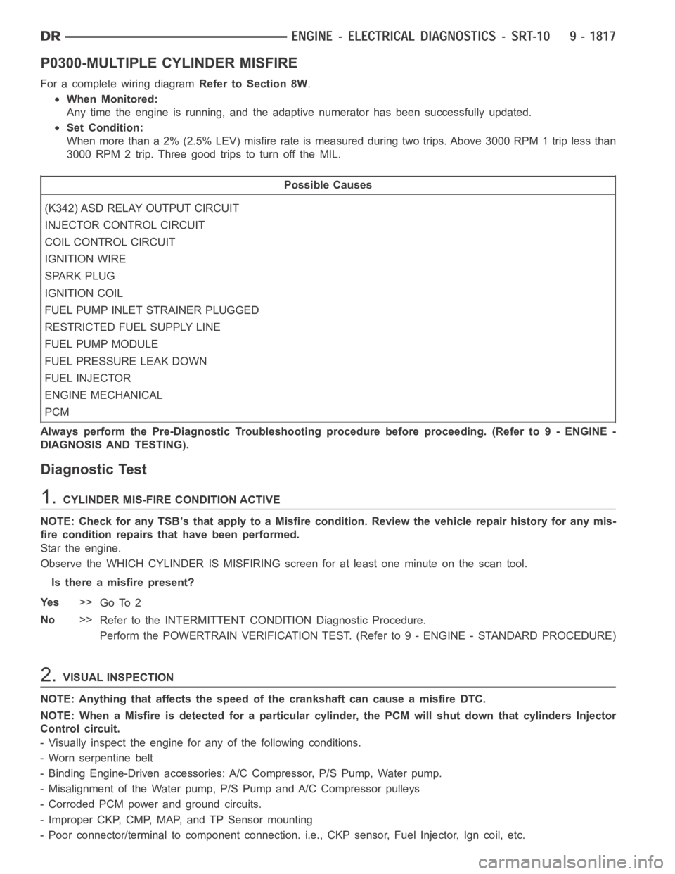
P0300-MULTIPLE CYLINDER MISFIRE
For a complete wiring diagramRefer to Section 8W.
When Monitored:
Any time the engine is running, and the adaptive numerator has been successfully updated.
Set Condition:
When more than a 2% (2.5% LEV) misfire rate is measured during two trips. Above 3000 RPM 1 trip less than
3000 RPM 2 trip. Three good trips to turn off the MIL.
Possible Causes
(K342) ASD RELAY OUTPUT CIRCUIT
INJECTOR CONTROL CIRCUIT
COIL CONTROL CIRCUIT
IGNITION WIRE
SPARK PLUG
IGNITION COIL
FUEL PUMP INLET STRAINER PLUGGED
RESTRICTED FUEL SUPPLY LINE
FUEL PUMP MODULE
FUEL PRESSURE LEAK DOWN
FUEL INJECTOR
ENGINE MECHANICAL
PCM
Always perform the Pre-Diagnostic Troubleshooting procedure before proceeding. (Refer to 9 - ENGINE -
DIAGNOSIS AND TESTING).
Diagnostic Test
1.CYLINDER MIS-FIRE CONDITION ACTIVE
NOTE: Check for any TSB’s that apply to a Misfire condition. Review the vehicle repair history for any mis-
fire condition repairs that have been performed.
Star the engine.
Observe the WHICH CYLINDER IS MISFIRING screen for at least one minute on the scan tool.
Is there a misfire present?
Ye s>>
Go To 2
No>>
Refer to the INTERMITTENT CONDITION Diagnostic Procedure.
Perform the POWERTRAIN VERIFICATION TEST. (Refer to 9 - ENGINE - STANDARD PROCEDURE)
2.VISUAL INSPECTION
NOTE: Anything that affects the speed of the crankshaft can cause a misfireDTC.
NOTE: When a Misfire is detected for a particular cylinder, the PCM will shut down that cylinders Injector
Control circuit.
- Visually inspect the engine for any of the following conditions.
- Worn serpentine belt
- Binding Engine-Driven accessories: A/C Compressor, P/S Pump, Water pump.
- Misalignment of the Water pump, P/S Pump and A/C Compressor pulleys
- Corroded PCM power and ground circuits.
- Improper CKP, CMP, MAP, and TP Sensor mounting
- Poor connector/terminal to component connection. i.e., CKP sensor, Fuel Injector, Ign coil, etc.