2006 DODGE RAM SRT-10 water pump
[x] Cancel search: water pumpPage 1205 of 5267

When Monitored:
Any time the engine is running, and the adaptive numerator has been successfully updated.
Set Condition:
When more than a 1% misfire rate is measured during two trips, or with a 6% to 30% misfire rate during one
trip.
Possible Causes
(K342) ASD RELAY OUTPUT CIRCUIT
(K115) INJECTOR CONTROL CIRCUIT
(K18) COIL CONTROL CIRCUIT
IGNITION WIRE
SPARK PLUG
IGNITION COIL
FUEL PUMP INLET STRAINER PLUGGED
RESTRICTED FUEL SUPPLY LINE
FUEL PUMP MODULE
FUEL PRESSURE LEAK DOWN
FUEL INJECTOR
ENGINE MECHANICAL
PCM
Always perform the Pre-Diagnostic Troubleshooting procedure before proceeding. (Refer to 9 - ENGINE -
DIAGNOSIS AND TESTING).
Diagnostic Test
1.CYLINDER MIS-FIRE CONDITION ACTIVE
Engine running.
Observe the WHICH CYLINDER IS MISFIRING screen for at least one minute on the scan tool.
Isthereamisfirepresentatthistime?
Ye s>>
Go To 2
No>>
Refer to the INTERMITTENT CONDITION Diagnostic Procedure.
Perform the POWERTRAIN VERIFICATION TEST. (Refer to 9 - ENGINE - STANDARD PROCEDURE)
2.VISUAL INSPECTION
NOTE: Anything that affects the speed of the crankshaft can cause a misfireDTC.
NOTE: When a Misfire is detected for a particular cylinder, the PCM will shut down that cylinders Injector
Control circuit.
- Visually inspect the engine for any of the following conditions.
- Worn serpentine belt
- Binding Engine-Driven accessories: A/C Compressor, P/S Pump, Water pump.
- Misalignment of the Water pump, P/S Pump and A/C Compressor pulleys
- Corroded PCM power and ground circuits.
- Improper CKP, CMP, MAP, and TP Sensor mounting
- Poor connector/terminal to component connection. i.e., CKP sensor, Fuel Injector, Ign coil, etc.
- Vacuum leaks
- Restricted Air Induction system or Exhaust system.
Page 1214 of 5267

When Monitored:
Any time the engine is running, and the adaptive numerator has been successfully updated.
Set Condition:
When more than a 1% misfire rate is measured during two trips, or with a 6% to 30% misfire rate during one
trip.
Possible Causes
(K342) ASD RELAY OUTPUT CIRCUIT
(K116) INJECTOR CONTROL CIRCUIT
(K17) COIL CONTROL CIRCUIT
IGNITION WIRE
SPARK PLUG
IGNITION COIL
FUEL PUMP INLET STRAINER PLUGGED
RESTRICTED FUEL SUPPLY LINE
FUEL PUMP MODULE
FUEL PRESSURE LEAK DOWN
FUEL INJECTOR
ENGINE MECHANICAL
PCM
Always perform the Pre-Diagnostic Troubleshooting procedure before proceeding. (Refer to 9 - ENGINE -
DIAGNOSIS AND TESTING).
Diagnostic Test
1.CYLINDER MIS-FIRE CONDITION ACTIVE
Engine running.
Observe the WHICH CYLINDER IS MISFIRING screen for at least one minute on the scan tool.
Isthereamisfirepresentatthistime?
Ye s>>
Go To 2
No>>
Refer to the INTERMITTENT CONDITION Diagnostic Procedure.
Perform the POWERTRAIN VERIFICATION TEST. (Refer to 9 - ENGINE - STANDARD PROCEDURE)
2.VISUAL INSPECTION
NOTE: Anything that affects the speed of the crankshaft can cause a misfireDTC.
NOTE: When a Misfire is detected for a particular cylinder, the PCM will shut down that cylinders Injector
Control circuit.
- Visually inspect the engine for any of the following conditions.
- Worn serpentine belt
- Binding Engine-Driven accessories: A/C Compressor, P/S Pump, Water pump.
- Misalignment of the Water pump, P/S Pump and A/C Compressor pulleys
- Corroded PCM power and ground circuits.
- Improper CKP, CMP, MAP, and TP Sensor mounting
- Poor connector/terminal to component connection. i.e., CKP sensor, Fuel Injector, Ign coil, etc.
- Vacuum leaks
- Restricted Air Induction system or Exhaust system.
Page 1490 of 5267
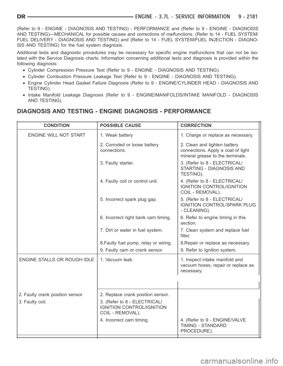
(Refer to 9 - ENGINE - DIAGNOSIS AND TESTING) - PERFORMANCE and (Refer to 9 - ENGINE - DIAGNOSIS
AND TESTING)—MECHANICAL for possible causes and corrections of malfunctions. (Refer to 14 - FUEL SYSTEM/
FUEL DELIVERY - DIAGNOSIS AND TESTING) and (Refer to 14 - FUEL SYSTEM/FUEL INJECTION - DIAGNO-
SIS AND TESTING) for the fuel system diagnosis.
Additional tests and diagnostic procedures may be necessary for specificengine malfunctions that can not be iso-
lated with the Service Diagnosis charts. Information concerning additional tests and diagnosis is provided within the
following diagnosis:
Cylinder Compression Pressure Test (Refer to 9 - ENGINE - DIAGNOSIS AND TESTING).
Cylinder Combustion Pressure LeakageTest (Refer to 9 - ENGINE - DIAGNOSISAND TESTING).
Engine Cylinder Head Gasket Failure Diagnosis (Refer to 9 - ENGINE/CYLINDER HEAD - DIAGNOSIS AND
TESTING).
Intake Manifold Leakage Diagnosis (Refer to 9 - ENGINE/MANIFOLDS/INTAKEMANIFOLD - DIAGNOSIS
AND TESTING).
DIAGNOSIS AND TESTING - ENGINE DIAGNOSIS - PERFORMANCE
CONDITION POSSIBLE CAUSE CORRECTION
ENGINE WILL NOT START 1. Weak battery 1. Charge or replace as necessary.
2. Corroded or loose battery
connections.2. Clean and tighten battery
connections. Apply a coat of light
mineral grease to the terminals.
3. Faulty starter. 3. (Refer to 8 - ELECTRICAL/
STARTING - DIAGNOSIS AND
TESTING).
4. Faulty coil or control unit. 4. (Refer to 8 - ELECTRICAL/
IGNITION CONTROL/IGNITION
COIL - REMOVAL).
5. Incorrect spark plug gap. 5. (Refer to 8 - ELECTRICAL/
IGNITION CONTROL/SPARK PLUG
- CLEANING).
6. Incorrect right bank cam timing. 6. Refer to engine timing in this
section.
7. Dirt or water in fuel system. 7. Clean system and replace fuel
filter.
8.Faulty fuel pump, relay or wiring. 8.Repair or replace as necessary.
9. Faulty cam or crank sensor 9. Refer to Ignition system.
ENGINE STALLS OR ROUGH IDLE 1. Vacuum leak. 1. Inspect intake manifold and
vacuum hoses, repair or replace as
necessary.
2. Faulty crank position sensor 2. Replace crank position sensor.
3. Faulty coil. 3. (Refer to 8 - ELECTRICAL/
IGNITION CONTROL/IGNITION
COIL - REMOVAL).
4. Incorrect cam timing. 4. (Refer to 9 - ENGINE/VALVE
TIMING - STANDARD
PROCEDURE).
Page 1491 of 5267
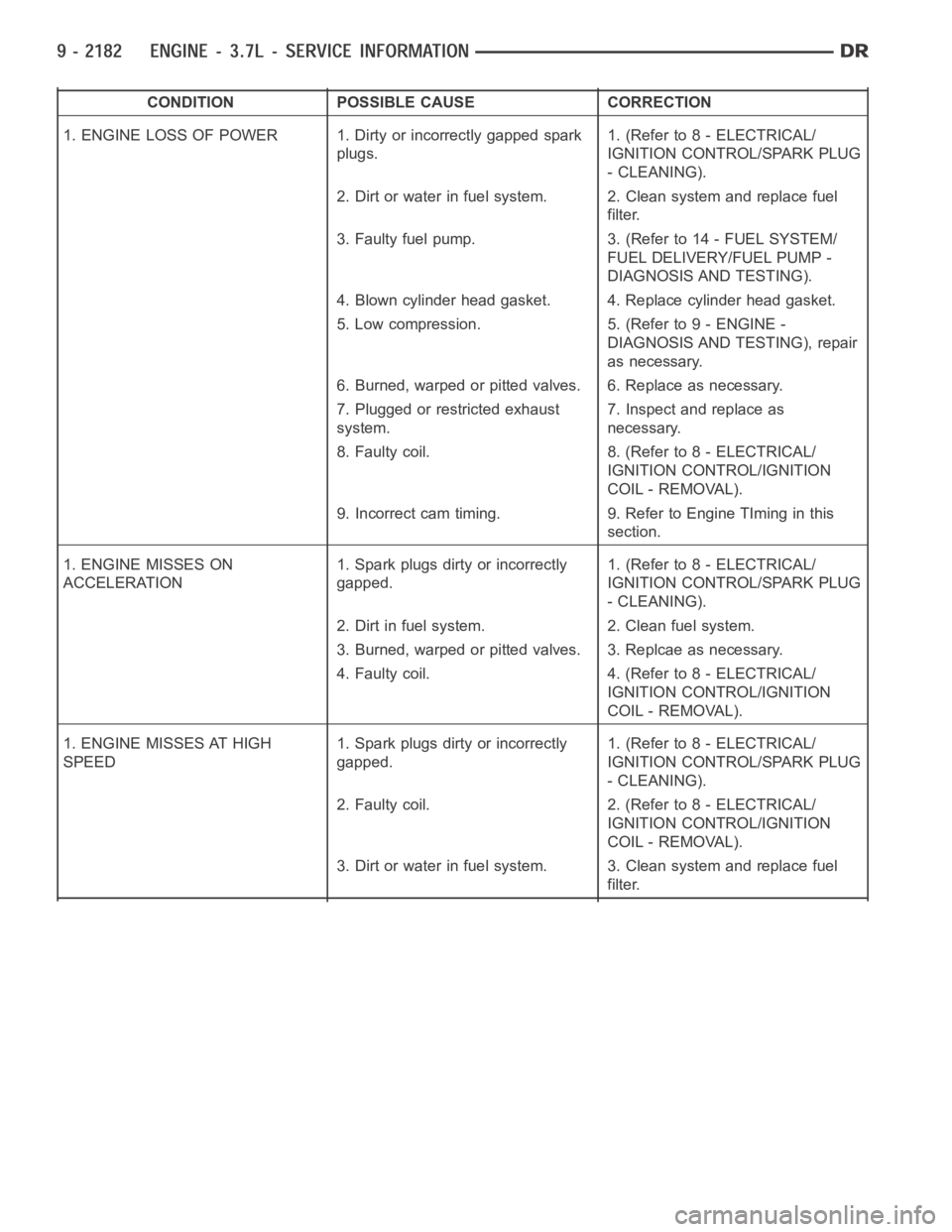
CONDITION POSSIBLE CAUSE CORRECTION
1. ENGINE LOSS OF POWER 1. Dirty or incorrectly gapped spark
plugs.1. (Refer to 8 - ELECTRICAL/
IGNITION CONTROL/SPARK PLUG
- CLEANING).
2. Dirt or water in fuel system. 2. Clean system and replace fuel
filter.
3. Faulty fuel pump. 3. (Refer to 14 - FUEL SYSTEM/
FUEL DELIVERY/FUEL PUMP -
DIAGNOSIS AND TESTING).
4. Blown cylinder head gasket. 4. Replace cylinder head gasket.
5. Low compression. 5. (Refer to 9 - ENGINE -
DIAGNOSIS AND TESTING), repair
as necessary.
6. Burned, warped or pitted valves. 6. Replace as necessary.
7. Plugged or restricted exhaust
system.7. Inspect and replace as
necessary.
8. Faulty coil. 8. (Refer to 8 - ELECTRICAL/
IGNITION CONTROL/IGNITION
COIL - REMOVAL).
9. Incorrect cam timing. 9. Refer to Engine TIming in this
section.
1. ENGINE MISSES ON
ACCELERATION1. Spark plugs dirty or incorrectly
gapped.1. (Refer to 8 - ELECTRICAL/
IGNITION CONTROL/SPARK PLUG
- CLEANING).
2. Dirt in fuel system. 2. Clean fuel system.
3. Burned, warped or pitted valves. 3. Replcae as necessary.
4. Faulty coil. 4. (Refer to 8 - ELECTRICAL/
IGNITION CONTROL/IGNITION
COIL - REMOVAL).
1. ENGINE MISSES AT HIGH
SPEED1. Spark plugs dirty or incorrectly
gapped.1. (Refer to 8 - ELECTRICAL/
IGNITION CONTROL/SPARK PLUG
- CLEANING).
2. Faulty coil. 2. (Refer to 8 - ELECTRICAL/
IGNITION CONTROL/IGNITION
COIL - REMOVAL).
3. Dirt or water in fuel system. 3. Clean system and replace fuel
filter.
Page 1494 of 5267
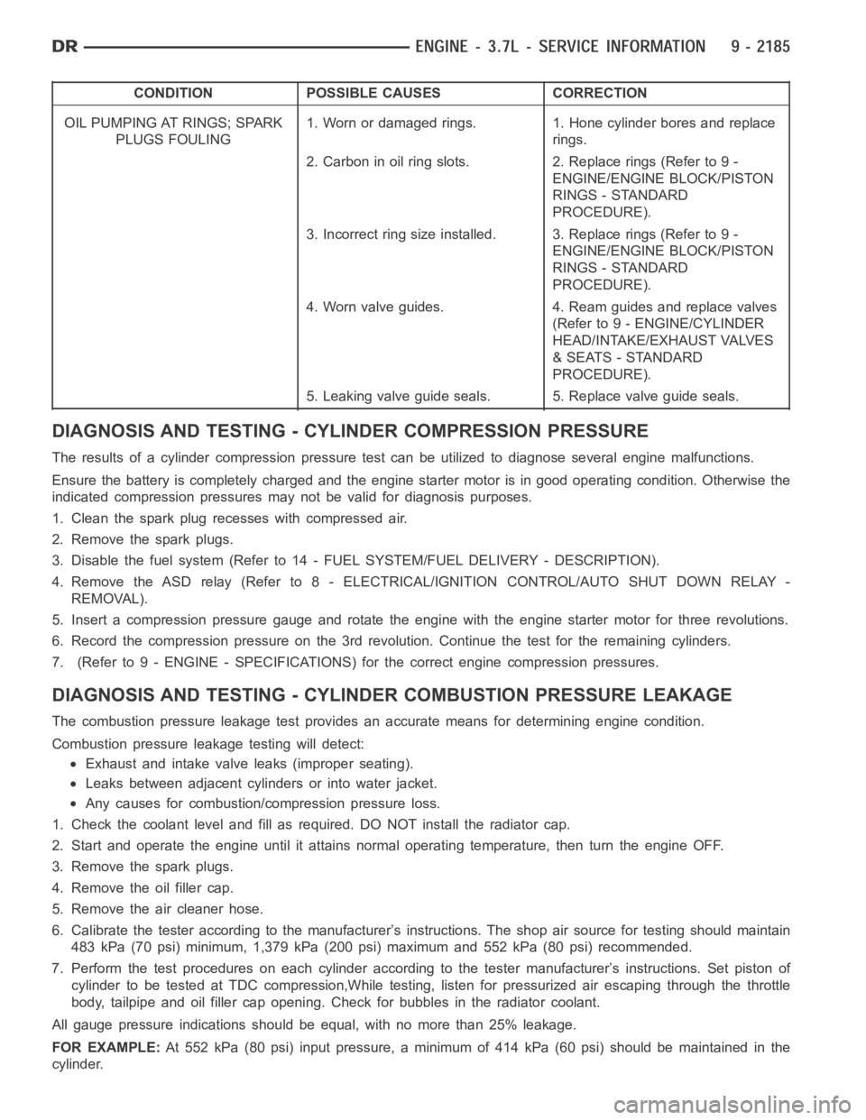
CONDITION POSSIBLE CAUSES CORRECTION
OIL PUMPING AT RINGS; SPARK
PLUGS FOULING1. Worn or damaged rings. 1. Hone cylinder bores and replace
rings.
2. Carbon in oil ring slots. 2. Replace rings (Refer to 9 -
ENGINE/ENGINE BLOCK/PISTON
RINGS - STANDARD
PROCEDURE).
3. Incorrect ring size installed. 3. Replace rings (Refer to 9 -
ENGINE/ENGINE BLOCK/PISTON
RINGS - STANDARD
PROCEDURE).
4. Worn valve guides. 4. Ream guides and replace valves
(Refer to 9 - ENGINE/CYLINDER
HEAD/INTAKE/EXHAUST VALVES
& SEATS - STANDARD
PROCEDURE).
5. Leaking valve guide seals. 5. Replace valve guide seals.
DIAGNOSIS AND TESTING - CYLINDER COMPRESSION PRESSURE
The results of a cylinder compressionpressure test can be utilized to diagnose several engine malfunctions.
Ensurethebatteryiscompletelychargedandtheenginestartermotorisingood operating condition. Otherwise the
indicated compression pressures may not be valid for diagnosis purposes.
1. Clean the spark plug recesses with compressed air.
2. Remove the spark plugs.
3. Disable the fuel system (Refer to 14 - FUEL SYSTEM/FUEL DELIVERY - DESCRIPTION).
4. Remove the ASD relay (Refer to 8 - ELECTRICAL/IGNITION CONTROL/AUTO SHUTDOWNRELAY-
REMOVAL).
5. Insert a compression pressure gauge and rotate the engine with the engine starter motor for three revolutions.
6. Record the compression pressure on the 3rd revolution. Continue the test for the remaining cylinders.
7. (Refer to 9 - ENGINE - SPECIFICATIONS) for the correct engine compression pressures.
DIAGNOSIS AND TESTING - CYLINDERCOMBUSTION PRESSURE LEAKAGE
The combustion pressure leakage test provides an accurate means for determining engine condition.
Combustion pressure leakage testing will detect:
Exhaust and intake valve leaks (improper seating).
Leaks between adjacent cylinders or into water jacket.
Any causes for combustion/compression pressure loss.
1. Check the coolant level and fill as required. DO NOT install the radiatorcap.
2. Start and operate the engine until it attains normal operating temperature, then turn the engine OFF.
3. Remove the spark plugs.
4. Remove the oil filler cap.
5. Remove the air cleaner hose.
6. Calibrate the tester according to the manufacturer’s instructions. The shop air source for testing should maintain
483 kPa (70 psi) minimum, 1,379 kPa (200 psi) maximum and 552 kPa (80 psi) recommended.
7. Perform the test procedures on each cylinder according to the tester manufacturer’s instructions. Set piston of
cylinder to be tested at TDC compression,While testing, listen for pressurized air escaping through the throttle
body, tailpipe and oil filler cap opening. Check for bubbles in the radiator coolant.
All gauge pressure indications should be equal, with no more than 25% leakage.
FOR EXAMPLE:At 552 kPa (80 psi) input pressure, a minimum of 414 kPa (60 psi) should be maintained in the
cylinder.
Page 1509 of 5267
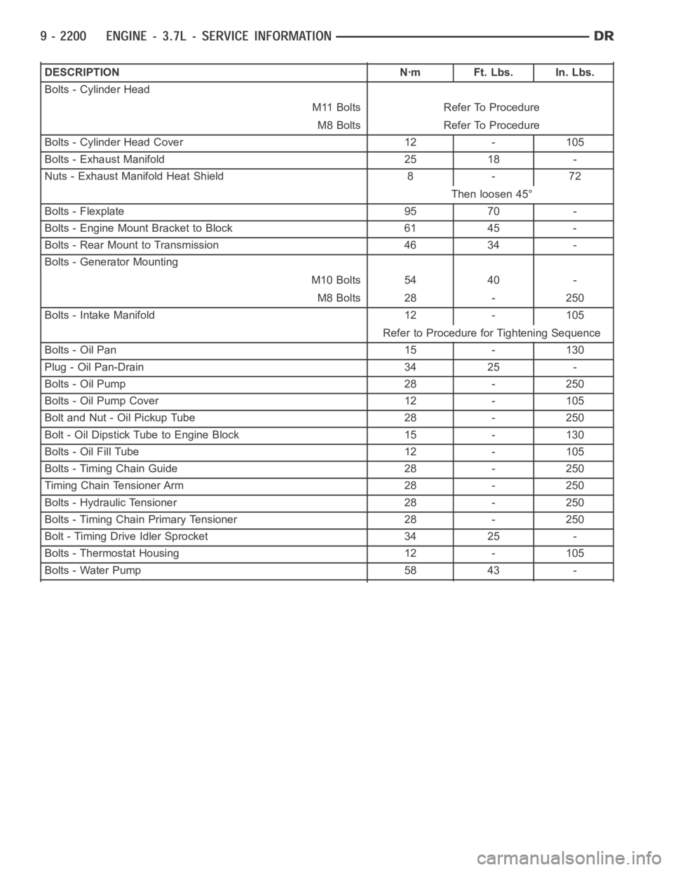
DESCRIPTION Nꞏm Ft. Lbs. In. Lbs.
Bolts - Cylinder Head
M11 Bolts Refer To Procedure
M8 Bolts Refer To Procedure
Bolts - Cylinder Head Cover 12 - 105
Bolts - Exhaust Manifold 25 18 -
Nuts - Exhaust Manifold Heat Shield 8 - 72
Then loosen 45°
Bolts - Flexplate 95 70 -
Bolts - Engine Mount Bracket to Block 61 45 -
Bolts - Rear Mount to Transmission 46 34 -
Bolts - Generator Mounting
M10 Bolts 54 40 -
M8 Bolts 28 - 250
Bolts - Intake Manifold 12 - 105
Refer to Procedure for Tightening Sequence
Bolts - Oil Pan 15 - 130
Plug - Oil Pan-Drain 34 25 -
Bolts - Oil Pump 28 - 250
Bolts - Oil Pump Cover 12 - 105
Bolt and Nut - Oil Pickup Tube 28 - 250
Bolt - Oil Dipstick Tube to Engine Block 15 - 130
Bolts - Oil Fill Tube 12 - 105
Bolts - Timing Chain Guide 28 - 250
Timing Chain Tensioner Arm 28 - 250
Bolts - Hydraulic Tensioner 28 - 250
Bolts - Timing Chain Primary Tensioner 28 - 250
Bolt - Timing Drive Idler Sprocket 34 25 -
Bolts - Thermostat Housing 12 - 105
Bolts - Water Pump 58 43 -
Page 1577 of 5267
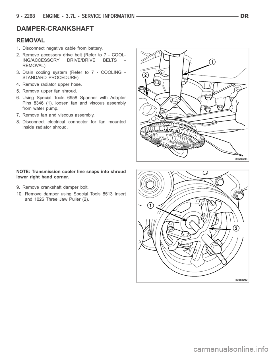
DAMPER-CRANKSHAFT
REMOVAL
1. Disconnect negative cable from battery.
2. Remove accessory drive belt (Refer to 7 - COOL-
ING/ACCESSORY DRIVE/DRIVE BELTS -
REMOVAL).
3. Drain cooling system (Refer to 7 - COOLING -
STANDARD PROCEDURE).
4. Remove radiator upper hose.
5. Remove upper fan shroud.
6. Using Special Tools 6958 Spanner with Adapter
Pins 8346 (1), loosen fan and viscous assembly
from water pump.
7. Remove fan and viscous assembly.
8. Disconnect electrical connector for fan mounted
inside radiator shroud.
NOTE: Transmission cooler line snaps into shroud
lower right hand corner.
9. Remove crankshaft damper bolt.
10. Remove damper using Special Tools 8513 Insert
and 1026 Three Jaw Puller (2).
Page 1614 of 5267
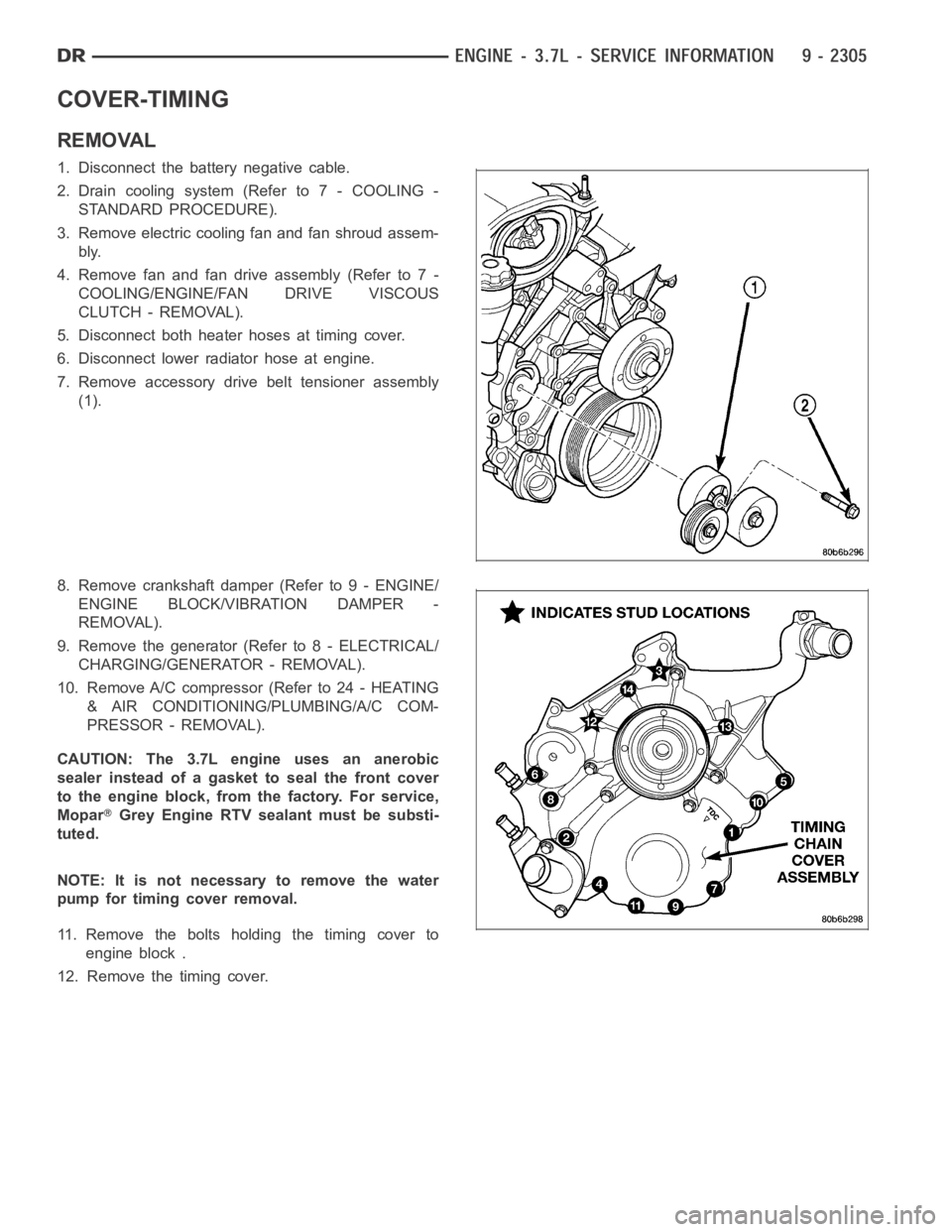
COVER-TIMING
REMOVAL
1. Disconnect the battery negative cable.
2. Drain cooling system (Refer to 7 - COOLING -
STANDARD PROCEDURE).
3. Remove electric cooling fan and fan shroud assem-
bly.
4. Remove fan and fan drive assembly (Refer to 7 -
COOLING/ENGINE/FAN DRIVE VISCOUS
CLUTCH - REMOVAL).
5. Disconnect both heater hoses at timing cover.
6. Disconnect lower radiator hose at engine.
7. Remove accessory drive belt tensioner assembly
(1).
8. Remove crankshaft damper (Refer to 9 - ENGINE/
ENGINE BLOCK/VIBRATION DAMPER -
REMOVAL).
9. Remove the generator (Refer to 8 - ELECTRICAL/
CHARGING/GENERATOR - REMOVAL).
10. Remove A/C compressor (Refer to 24 - HEATING
& AIR CONDITIONING/PLUMBING/A/C COM-
PRESSOR - REMOVAL).
CAUTION: The 3.7L engine uses an anerobic
sealer instead of a gasket to seal the front cover
to the engine block, from the factory. For service,
Mopar
Grey Engine RTV sealant must be substi-
tuted.
NOTE: It is not necessary to remove the water
pump for timing cover removal.
11. Remove the bolts holding the timing cover to
engine block .
12. Remove the timing cover.