2006 DODGE RAM SRT-10 water pump
[x] Cancel search: water pumpPage 1893 of 5267
17. Remove the dipstick support bolt.
18. Drain the engine oil.
19. Remove the oil pan and pick up tube (Refer to 9 - ENGINE/LUBRICATION/OILPA N - R E M O VA L ) .
NOTE: It is not necessary to remove water pump for timing cover removal.
20. Remove timing cover bolts and remove cover.
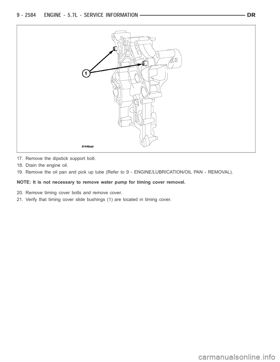
21. Verify that timing cover slide bushings (1) are located in timing cover.
Page 1908 of 5267
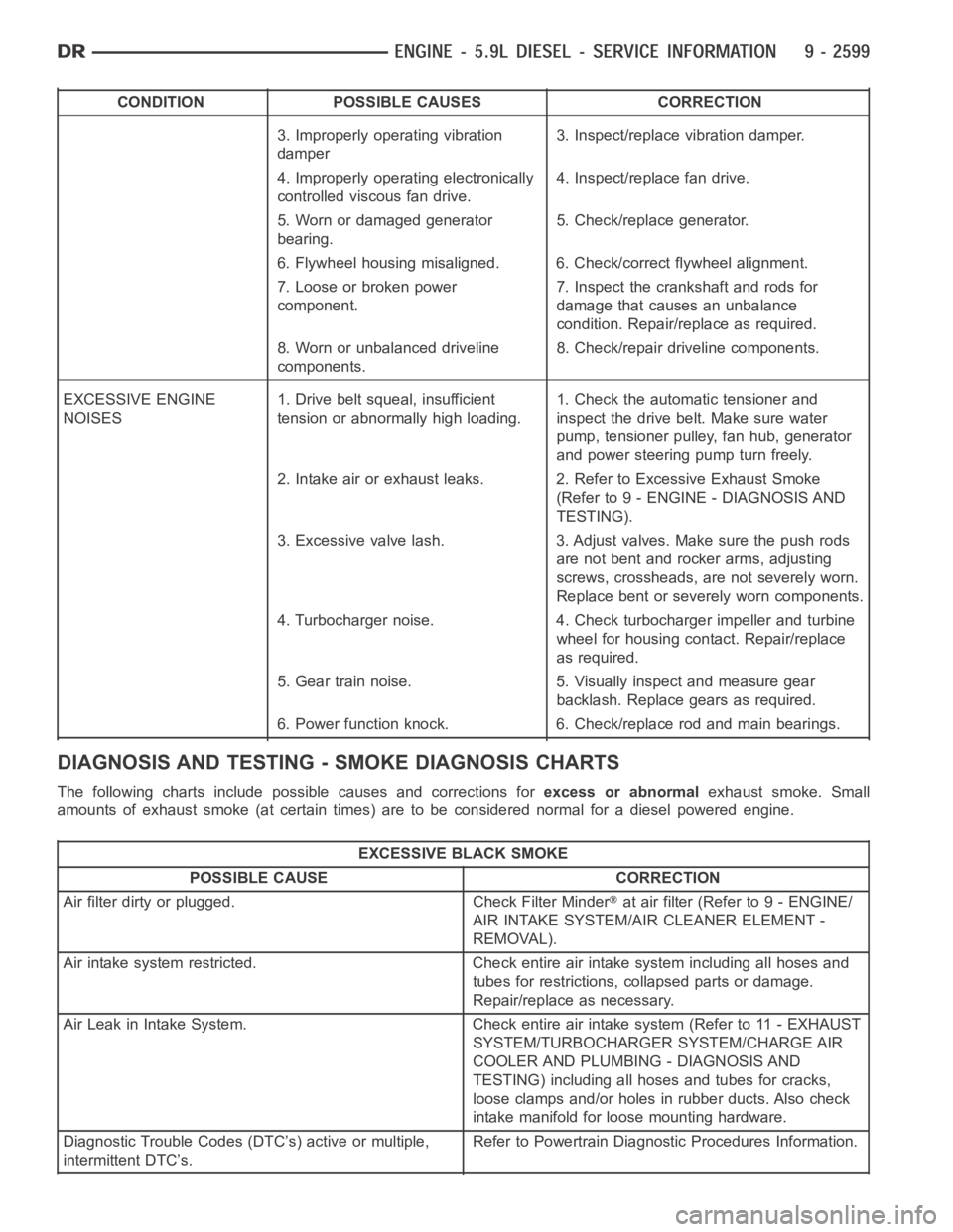
CONDITION POSSIBLE CAUSES CORRECTION
3. Improperly operating vibration
damper3. Inspect/replace vibration damper.
4. Improperly operating electronically
controlled viscous fan drive.4. Inspect/replace fan drive.
5. Worn or damaged generator
bearing.5. Check/replace generator.
6. Flywheel housing misaligned. 6. Check/correct flywheel alignment.
7. Loose or broken power
component.7. Inspect the crankshaft and rods for
damage that causes an unbalance
condition. Repair/replace as required.
8. Worn or unbalanced driveline
components.8. Check/repair driveline components.
EXCESSIVE ENGINE
NOISES1. Drive belt squeal, insufficient
tension or abnormally high loading.1. Check the automatic tensioner and
inspect the drive belt. Make sure water
pump, tensioner pulley, fan hub, generator
and power steering pump turn freely.
2. Intake air or exhaust leaks. 2. Refer to Excessive Exhaust Smoke
(Refer to 9 - ENGINE - DIAGNOSIS AND
TESTING).
3. Excessive valve lash. 3. Adjust valves. Make sure the push rods
are not bent and rocker arms, adjusting
screws, crossheads, are not severely worn.
Replace bent or severely worn components.
4. Turbocharger noise. 4. Check turbocharger impeller and turbine
wheel for housing contact. Repair/replace
as required.
5. Gear train noise. 5. Visually inspect and measure gear
backlash. Replace gears as required.
6. Power function knock. 6. Check/replace rod and main bearings.
DIAGNOSIS AND TESTING -SMOKE DIAGNOSIS CHARTS
The following charts include possible causes and corrections forexcess or abnormalexhaust smoke. Small
amounts of exhaust smoke (at certain times) are to be considered normal fora diesel powered engine.
EXCESSIVE BLACK SMOKE
POSSIBLE CAUSE CORRECTION
Air filter dirty or plugged. Check Filter Minder
at air filter (Refer to 9 - ENGINE/
AIR INTAKE SYSTEM/AIR CLEANER ELEMENT -
REMOVAL).
Air intake system restricted. Check entire air intake system including all hoses and
tubes for restrictions, collapsed parts or damage.
Repair/replace as necessary.
Air Leak in Intake System. Check entire air intake system (Refer to 11 - EXHAUST
SYSTEM/TURBOCHARGER SYSTEM/CHARGE AIR
COOLER AND PLUMBING - DIAGNOSIS AND
TESTING) including all hoses and tubes for cracks,
loose clamps and/or holes in rubber ducts. Also check
intake manifold for loose mounting hardware.
Diagnostic Trouble Codes (DTC’s) active or multiple,
intermittent DTC’s.Refer to Powertrain Diagnostic Procedures Information.
Page 2024 of 5267
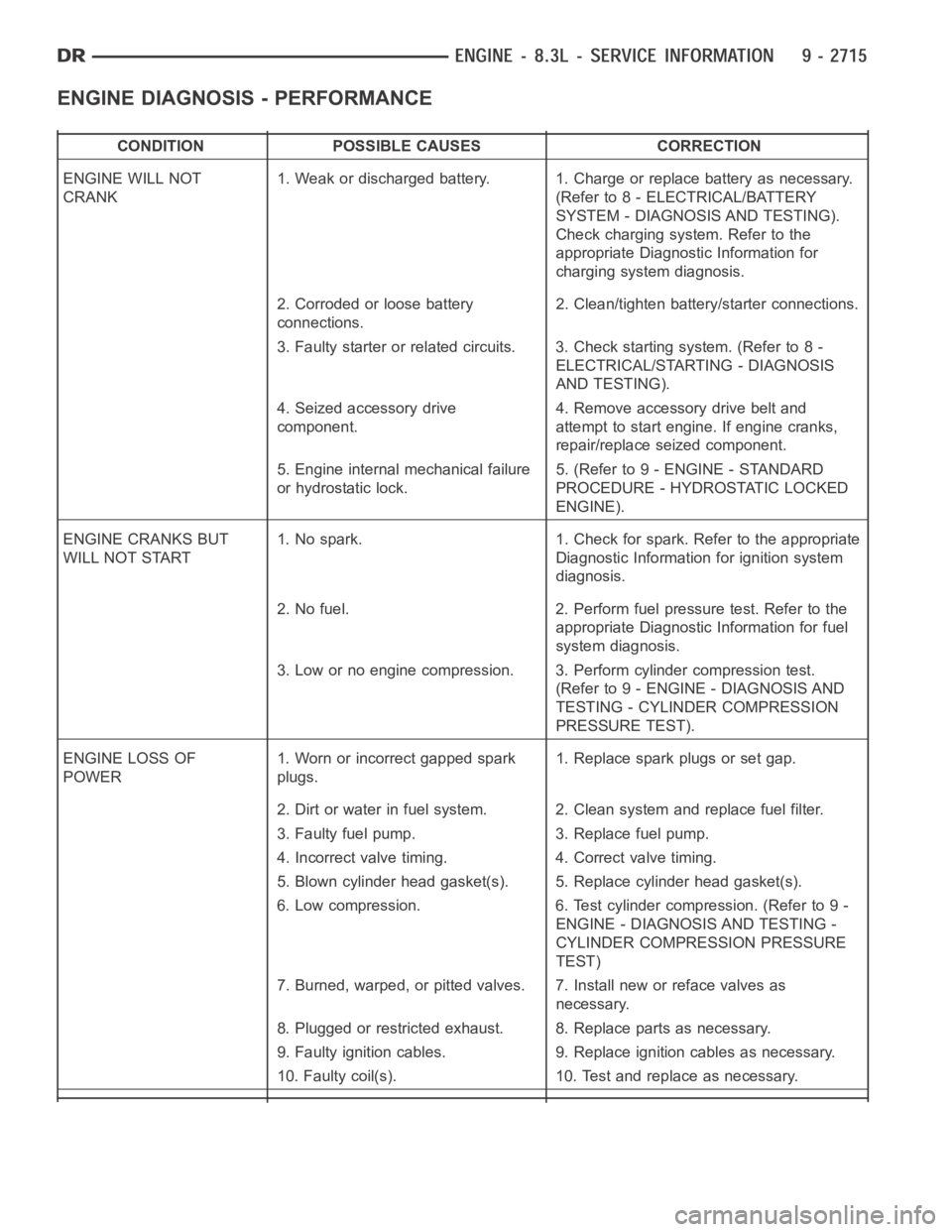
ENGINE DIAGNOSIS - PERFORMANCE
CONDITION POSSIBLE CAUSES CORRECTION
ENGINE WILL NOT
CRANK1. Weak or discharged battery. 1. Charge or replace battery as necessary.
(Refer to 8 - ELECTRICAL/BATTERY
SYSTEM - DIAGNOSIS AND TESTING).
Check charging system. Refer to the
appropriate Diagnostic Information for
charging system diagnosis.
2. Corroded or loose battery
connections.2. Clean/tighten battery/starter connections.
3. Faulty starter or related circuits. 3. Check starting system. (Refer to8-
ELECTRICAL/STARTING - DIAGNOSIS
AND TESTING).
4. Seized accessory drive
component.4. Remove accessory drive belt and
attempt to start engine. If engine cranks,
repair/replace seized component.
5. Engine internal mechanical failure
or hydrostatic lock.5. (Refer to 9 - ENGINE - STANDARD
PROCEDURE - HYDROSTATIC LOCKED
ENGINE).
ENGINE CRANKS BUT
WILL NOT START1. No spark. 1. Check for spark. Refer to the appropriate
Diagnostic Information for ignition system
diagnosis.
2. No fuel. 2. Perform fuel pressure test. Refer to the
appropriate Diagnostic Information for fuel
system diagnosis.
3. Low or no engine compression. 3. Perform cylinder compression test.
(Refer to 9 - ENGINE - DIAGNOSIS AND
TESTING - CYLINDER COMPRESSION
PRESSURE TEST).
ENGINE LOSS OF
POWER1. Worn or incorrect gapped spark
plugs.1. Replace spark plugs or set gap.
2. Dirt or water in fuel system. 2. Clean system and replace fuel filter.
3. Faulty fuel pump. 3. Replace fuel pump.
4. Incorrect valve timing. 4. Correct valve timing.
5. Blown cylinder head gasket(s). 5. Replace cylinder head gasket(s).
6. Low compression. 6. Test cylinder compression. (Refer to 9 -
ENGINE - DIAGNOSIS AND TESTING -
CYLINDER COMPRESSION PRESSURE
TEST)
7. Burned, warped, or pitted valves. 7. Install new or reface valves as
necessary.
8. Plugged or restricted exhaust. 8. Replace parts as necessary.
9. Faulty ignition cables. 9. Replace ignition cables as necessary.
10. Faulty coil(s). 10. Test and replace as necessary.
Page 2046 of 5267
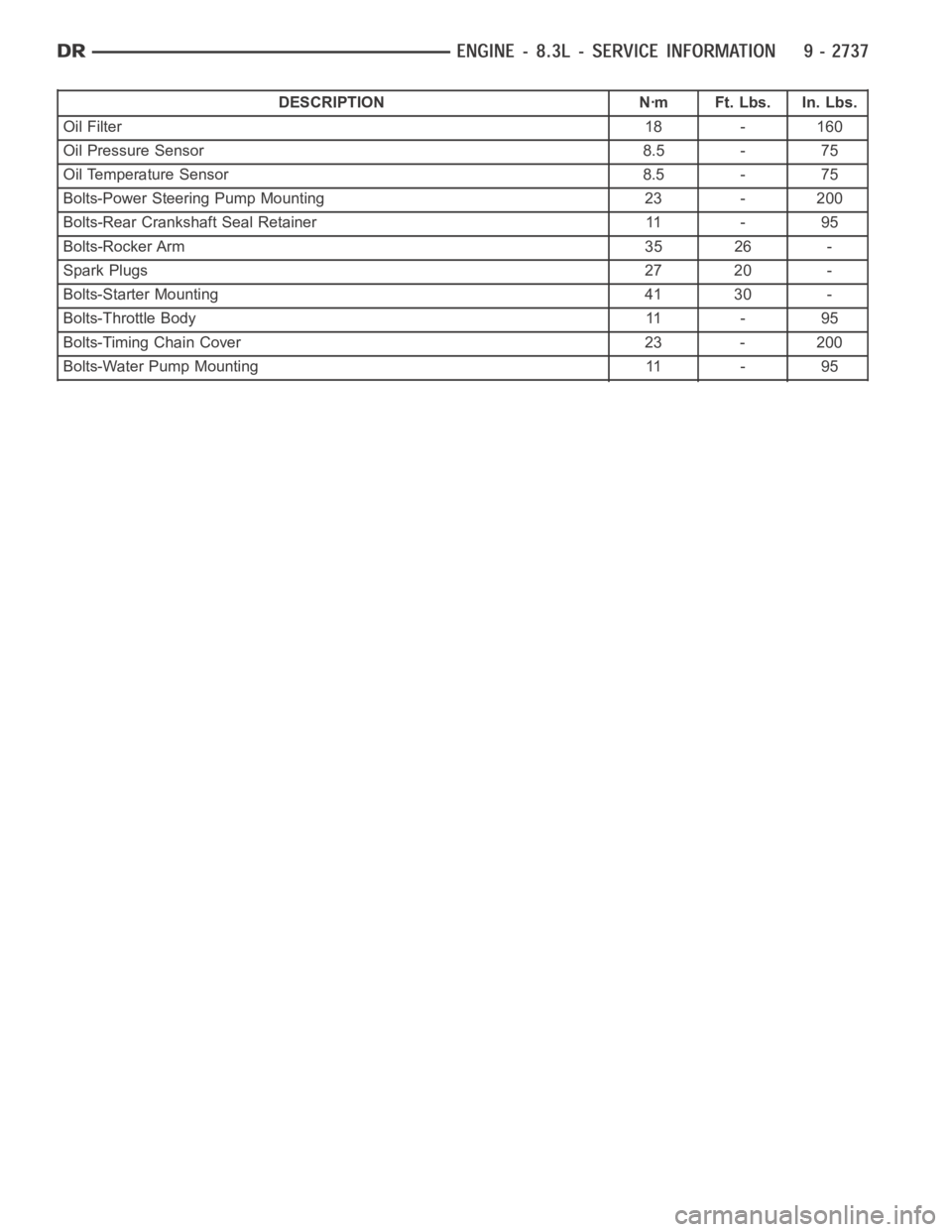
DESCRIPTION Nꞏm Ft. Lbs. In. Lbs.
Oil Filter18 - 160
Oil Pressure Sensor 8.5 - 75
Oil Temperature Sensor 8.5 - 75
Bolts-Power Steering Pump Mounting 23 - 200
Bolts-Rear Crankshaft Seal Retainer 11 - 95
Bolts-Rocker Arm 35 26 -
Spark Plugs27 20 -
Bolts-Starter Mounting 41 30 -
Bolts-Throttle Body 11 - 95
Bolts-Timing Chain Cover 23 - 200
Bolts-Water Pump Mounting 11 - 95
Page 2086 of 5267
LUBRICATION
DESCRIPTION
The engine lubrication system is a full-flow filtration pressure feed type.
OPERATION
Engine oil stored in the oil pan is taken in and discharged by an internal geartypeoilpump,whichisdrivenbythe
crankshaft. A pressure relief valve is located in the timing chain case cover; it regulates oil pressure. The oil is
pumped through an oil filter and feeds a main oil gallery. Also, oil is routedtoanexternaloilcooler.Themainoil
gallery feeds oil under pressure to the main bearings, connecting rod bearings, and camshaft bearings. Passages in
the cylinder block feed oil to the hydraulic lifters. The oil then flows through hollow pushrods, which feed the rocker
arm pivots.
DIAGNOSIS AND TESTING
CHECKING ENGINE OIL PRESSURE
1. Remove oil pressure sensor (Refer to 9 - ENGINE/LUBRICATION/OIL PRESSURE SENSOR - REMOVAL).
2. Install oil pressure gauge.
3. Warm engine at high idle until thermostat opens.
CAUTION: If oil pressure is 0 at idle, Do Not Run engine at 3000 RPM.
4. Oil pressure should be 68.9 kPa (10 psi) at idle or 310 - 517 kPa (45 - 75 psi)at 3000 RPM.
5. If oil pressure is 0 at idle, shut off engine. Check for a clogged oil pick-up screen or a pressure relief valve stuck
open.
ENGINE OIL LEAK
Begin with a thorough visual inspection of the engine, particularly at thearea of the suspected leak. If an oil leak
source is not readily identifiable, thefollowingstepsshouldbefollowed:
1. Do not clean or degrease the engine at this time because some solvents maycause rubber to swell, temporarily
stopping the leak.
2. Add an oil soluble dye (use as recommended by manufacturer). Start the engine and let idle for approximately 15
minutes. Check the oil dipstick to make sure the dye is thoroughly mixed as indicated with a bright yellow color
under a black light.
3. Using a black light, inspect the entire engine for fluorescent dye, particularly at the suspected area of oil leak. If
the oil leak is found and identified, repair per service manual instructions.
4. If dye is not observed, drive the vehicle at various speeds for approximately 24 km (15 miles), and repeat inspec-
tion.If the oil leak source is not positively identified at this time, proceed with the air leak detection test
method.
Air Leak Detection Test Method
1. Remove the PCV valve from the IAFM. Cap or plug the PCV valve grommet.
2. Attach an air hose with pressure gauge and regulator to the dipstick tube.
CAUTION: Do not subject the engine assembly to more than 20.6 kPa (3 PSI) of test pressure.
3. Gradually apply air pressure from 6.89 - 17.23 kPa (1 - 2.5 psi) maximum while applying soapy water at the
suspected source. Adjust the regulator to the suitable test pressure thatprovide the best bubbles which will pin-
point the leak source. If the oil leak is detected and identified, repair per service manual procedures.
4. If the leakage occurs at the rear oil seal area, refer to the section, Inspection for Rear Seal Area Leak.
5. If no leaks are detected, turn off the air supply and remove the air hose and all plugs and caps. Install the PCV
valve.
6. Clean the oil off the suspect oil leak area using a suitable solvent. Drive the vehicle at various speeds approx-
imately 24 km (15 miles). Inspect the engine for signs of an oil leak by usinga black light.
Page 2090 of 5267
COOLER & LINES-OIL
DESCRIPTION
An engine oil cooler is used on all models. The cooler is a coolant-to-oil type and mounted on the right front inner
fender.
OPERATION
Engine oil travels from the oil pump and filter to the oil cooler via an oil supply line. The oil is cooled and returned
to the engine via an oil return line. Engine oil is then pumped into the main oil gallery. Engine coolant flows into the
cooler from the heater return hose and exits into the water pump inlet nipple.
STANDARD PROCEDURE - OIL COOLER LINE QUICK CONNECT FITTING
DISASSEMBLY/ASSEMBLY
DISASSEMBLY
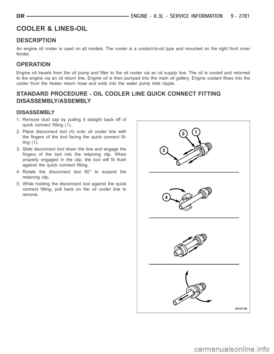
1. Remove dust cap by pulling it straight back off of
quick connect fitting (1).
2. Place disconnect tool (4) onto oil cooler line with
the fingers of the tool facing the quick connect fit-
ting (1).
3. Slide disconnect tool down the line and engage the
fingers of the tool into the retaining clip. When
properly engaged in the clip, the tool will fit flush
against the quick connect fitting.
4. Rotate the disconnect tool 60° to expand the
retaining clip.
5. While holding the disconnect tool against the quick
connect fitting, pull back on the oil cooler line to
remove.
Page 2341 of 5267
page page
FUEL DELIVERY - DIESEL
DESCRIPTION - DIESEL FUEL SYSTEM ....... 105
STANDARD PROCEDURE
WATER DRAINING AT FUEL FILTER ......... 106
CLEANING FUEL SYSTEM PARTS .......... 106
FUEL SYSTEM PRIMING................... 106
DRAINING FUEL TANK - DIESEL............ 107
SPECIFICATIONS
FUEL INJECTOR FIRING ORDER - DIESEL . . 107
TORQUE .................................. 107
SPECIAL TOOLS
DIESEL FUEL SYSTEM . .................... 109
FILTER - FUEL / WATER SEPARATOR
DESCRIPTION ............................... 111
OPERATION ................................. 111
REMOVAL ................................... 111
INSTALLATION .............................. 113
HEATER-FUEL
DESCRIPTION ............................... 115
OPERATION ................................. 115
DIAGNOSIS AND TESTING
FUEL HEATER ............................. 115
REMOVAL ................................... 116
PUMP - FUEL INJECTION
DESCRIPTION ............................... 117
OPERATION ................................. 117
DIAGNOSIS AND TESTING
FUEL INJECTION PUMP TIMING ............ 117
REMOVAL ................................... 117
INSTALLATION .............................. 120
SENSOR - FUEL LEVEL SENDING UNIT
DESCRIPTION ............................... 124
OPERATION ................................. 124
REMOVAL
REMOVAL/INSTALLATION .................. 124
LINES - FUEL
DESCRIPTION ............................... 125
OPERATION ................................. 125DIAGNOSIS AND TESTING
HIGH-PRESSURE FUEL LINE LEAKS........ 125
REMOVAL ................................... 126
INSTALLATION .............................. 127
SENSOR - FUEL PRESSURE
DESCRIPTION ............................... 129
OPERATION ................................. 129
REMOVAL ................................... 129
INSTALLATION .............................. 129
VALVE - FUEL PRESSURE LIMITING
DESCRIPTION ............................... 130
OPERATION ................................. 130
REMOVAL ................................... 130
INSTALLATION .............................. 131
TA N K - F U E L
DESCRIPTION ............................... 132
REMOVAL ................................... 132
INSTALLATION .............................. 133
MODULE - FUEL TANK
DESCRIPTION ............................... 134
OPERATION ................................. 134
REMOVAL ................................... 134
INSTALLATION .............................. 134
PUMP - FUEL TRANSFER
DESCRIPTION ............................... 136
OPERATION ................................. 136
REMOVAL ................................... 136
INSTALLATION .............................. 136
VALVE - CASCADE OVERFLOW
DESCRIPTION ............................... 137
OPERATION ................................. 137
SENSOR-WATER IN FUEL
DESCRIPTION ............................... 138
OPERATION ................................. 138
REMOVAL ................................... 138
CIRCUIT - FUEL DRAIN
OPERATION ................................. 139
Page 2342 of 5267
FUEL DELIVERY - DIESEL
DESCRIPTION - DIESEL FUEL SYSTEM
WARNING: High-pressure fuel lines deliver diesel
fuel under extreme pressure from the injection
pump to the fuel injectors. This may be as high as
160,000 kpa (23,206 psi). Use extreme caution
when inspecting for high-pressure fuel leaks.
Inspect for high-pressure fuel leaks with a sheet of
cardboard. High fuel injection pressure can cause
personal injury if contact is made with the skin.
The fuel system used on the Cummins engine is an electronically controlled, Bosch HPCR (High-Pressure Common
Rail) system. The HPCR system consists of five main components:
Electric Fuel Transfer (lift) Pump Located in the Fuel Tank
Fuel Pump/Gear Pump (attached to fuel injection pump)
High-Pressure Fuel Injection Pump
Fuel Injection Rail
Fuel Injectors
Also to be considered as part of the overall fuel system are:
Accelerator Pedal
Air Cleaner Housing/Element
Check Valve Banjo Fitting at Rear of Cylinder Head
Fuel Connector Tubes
Fuel Drain Manifold (passage)
Fuel Drain Valve (at filter)
Fuel Filter/Water Separator
Fuel Heater
Fuel Heater Relay
Fuel Transfer Pump Relay
Fuel Level (gauge) Sending Unit
Fuel Pressure Limiting Valve
Fuel Tank
Fuel Tank Module (containing a fuel gauge sending unit, separate fuel filter located at bottom of tank module,
and fuel transfer pump)
Fuel Tank Filler/Vent Tube Assembly
Fuel Tank Filler Tube Cap
Fuel Tubes/Lines/Hoses
High-Pressure Fuel Injector Lines
In-Tank Fuel Filter (at bottom of fuel tank module)
Low-Pressure Fuel Supply Lines
Low-Pressure Fuel Return Lines
Overflow Valve
Quick-Connect Fuel Line Fittings
Accelerator Pedal Position Sensor (APPS) Located in Cab
Water Draining (maintenance)
Water-In-Fuel (WIF) Sensor
Screened Banjo Bolt (22)
The fuel injection pump supplies high pressure to the fuel rail independent of engine speed. This high pressure fuel
is then accumulated in the fuel rail. High pressure fuel is constantly supplied to the injectors by the fuel rail. The
Engine Control Module (ECM) controls the fueling and timing of the engine by actuating the injectors.