Page 1803 of 5267
3. Tighten cylinder head cover bolts and double
ended studs to 8Nꞏm (70 in. lbs). Begin torque
sequence in the middle of head cover and torque
bolts moving outward in a crisscross pattern from
top to bottom.
4. Before installing coil(s), apply dielectric grease to
inside of spark plug boots (1).
5. Install ignition coils.
Page 2066 of 5267

HEAD(S)-CYLINDER
REMOVAL - CYLINDER HEAD(S)
NOTE: Care must be taken to protect the intake
manifold and cylinder head covers powder coating
from scrapes and abrasions. This procedure cov-
ers either the left or right cylinder head.
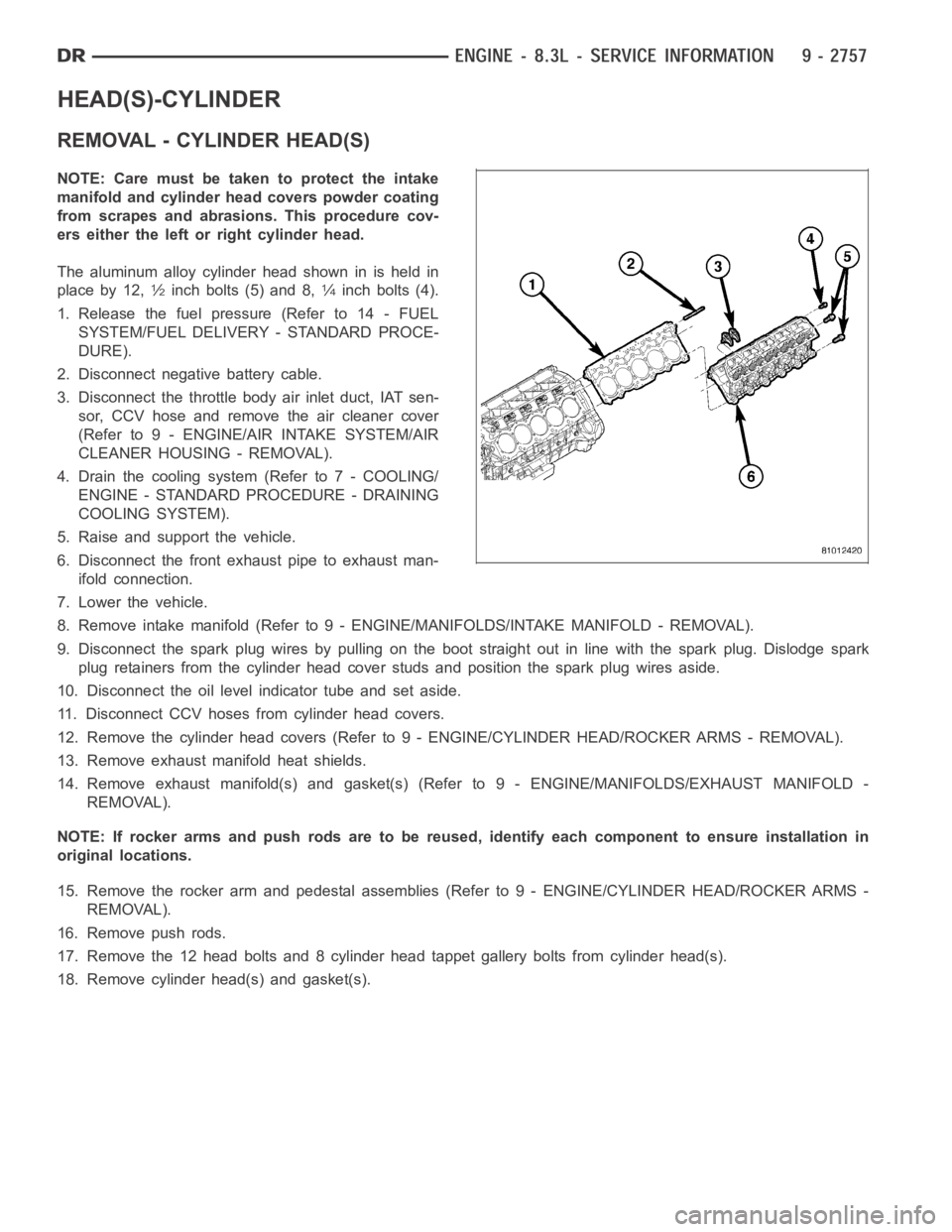
The aluminum alloy cylinder head shown in is held in
place by 12,
1⁄2inch bolts (5) and 8,1⁄4inch bolts (4).
1. Release the fuel pressure (Refer to 14 - FUEL
SYSTEM/FUEL DELIVERY - STANDARD PROCE-
DURE).
2. Disconnect negative battery cable.
3. Disconnect the throttle body air inlet duct, IAT sen-
sor, CCV hose and remove the air cleaner cover
(Refer to 9 - ENGINE/AIR INTAKE SYSTEM/AIR
CLEANER HOUSING - REMOVAL).
4. Drain the cooling system (Refer to 7 - COOLING/
ENGINE - STANDARD PROCEDURE - DRAINING
COOLING SYSTEM).
5. Raise and support the vehicle.
6. Disconnect the front exhaust pipe to exhaust man-
ifold connection.
7. Lower the vehicle.
8. Remove intake manifold (Refer to 9 - ENGINE/MANIFOLDS/INTAKE MANIFOLD-REMOVAL).
9. Disconnect the spark plug wires by pulling on the boot straight out in line with the spark plug. Dislodge spark
plug retainers from the cylinder head cover studs and position the spark plug wires aside.
10. Disconnect the oil level indicator tube and set aside.
11. Disconnect CCV hoses from cylinder head covers.
12. Remove the cylinder head covers (Refer to 9 - ENGINE/CYLINDER HEAD/ROCKER ARMS - REMOVAL).
13. Remove exhaust manifold heat shields.
14. Remove exhaust manifold(s) and gasket(s) (Refer to 9 - ENGINE/MANIFOLDS/EXHAUST MANIFOLD -
REMOVAL).
NOTE: If rocker arms and push rods are to be reused, identify each componentto ensure installation in
original locations.
15. Remove the rocker arm and pedestal assemblies (Refer to 9 - ENGINE/CYLINDER HEAD/ROCKER ARMS -
REMOVAL).
16. Remove push rods.
17. Remove the 12 head bolts and 8 cylinder head tappet gallery bolts from cylinder head(s).
18. Remove cylinder head(s) and gasket(s).
Page 2069 of 5267

COVER(S)-CYLINDER HEAD
REMOVAL
LEFT CYLINDER HEAD COVER
NOTE: Care must be taken to protect the cylinder
head cover powder coating from scrapes and
abrasions.
1. Disconnect CCV hose from cylinder head cover.
2. Disconnect left side spark plug wires by pulling on
the boot straight out in line with plug. Dislodge
spark plug wire retainers from cylinder head cover
studs. Reposition spark plug wires aside.
3. Disconnect the power brake booster vacuum hose
at the intake manifold and set aside.
NOTE: For reassembly purposes, identify location
of cylinder head cover attaching studs and bolts.
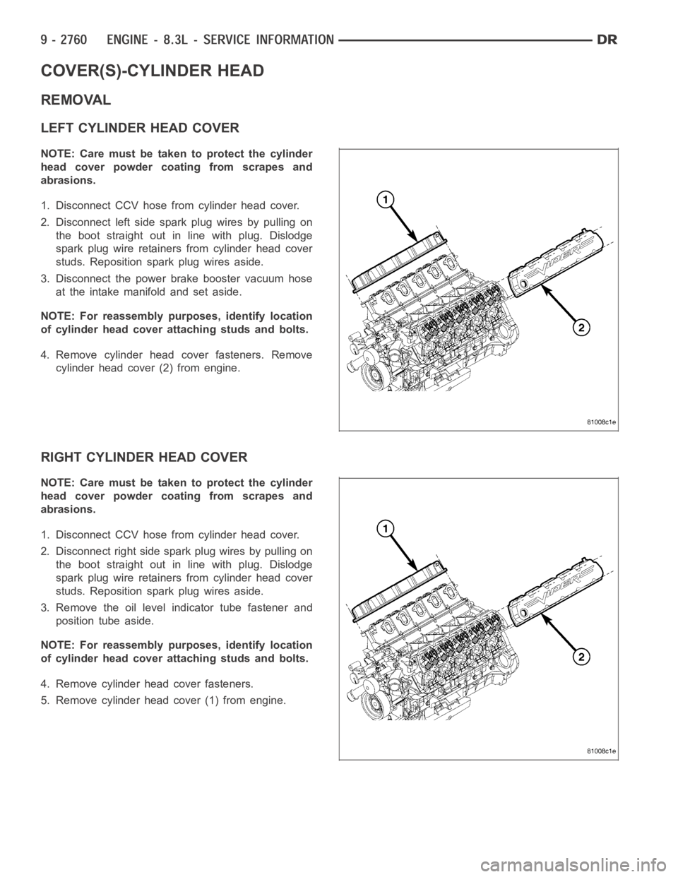
4. Remove cylinder head cover fasteners. Remove
cylinder head cover (2) from engine.
RIGHT CYLINDER HEAD COVER
NOTE: Care must be taken to protect the cylinder
head cover powder coating from scrapes and
abrasions.
1. Disconnect CCV hose from cylinder head cover.
2. Disconnect right side spark plug wires by pulling on
the boot straight out in line with plug. Dislodge
spark plug wire retainers from cylinder head cover
studs. Reposition spark plug wires aside.
3. Remove the oil level indicator tube fastener and
position tube aside.
NOTE: For reassembly purposes, identify location
of cylinder head cover attaching studs and bolts.
4. Remove cylinder head cover fasteners.
5. Remove cylinder head cover (1) from engine.
Page 2469 of 5267

TIE ROD END
DIAGNOSIS AND TESTING
OUTERTIERODEND
NOTE: If the outer tie rod end is equipped with a lubrication fitting, grease the joint then road test the vehi-
cle before performing test.
1. Raise the front of the vehicle. Place safety floor stands under both lower control arms as far outboard as pos-
sible. Lower the vehicle to allow the stands to support some or all of the vehicle weight.
2. Remove the front tires.
3. Mount a dial indicator solidly to the vehicle steering knuckle and then zero the dial indicator.
4. Position indicator plunger on the topside of the outer tie rod end.
NOTE: The dial indicator plunger must be perpendicular to the machined surface of the outer tie rod end.
5. Position a pry bar in order to pry downwards on the outer tie rod end.
6. If the travel exceeds 0.5 mm (0.020 in.), replace the outer tie rod end (Refer to 19 - STEERING/LINKAGE/TIE
ROD END - REMOVAL).
7. If the outer tie rod end is within specs reinstall the front tires (Refer to 22 - TIRES/WHEELS/WHEELS - STAN-
DARD PROCEDURE).
REMOVAL - OUTER TIE ROD END
NOTE: Do not twist the boot anytime during
removal or installation.
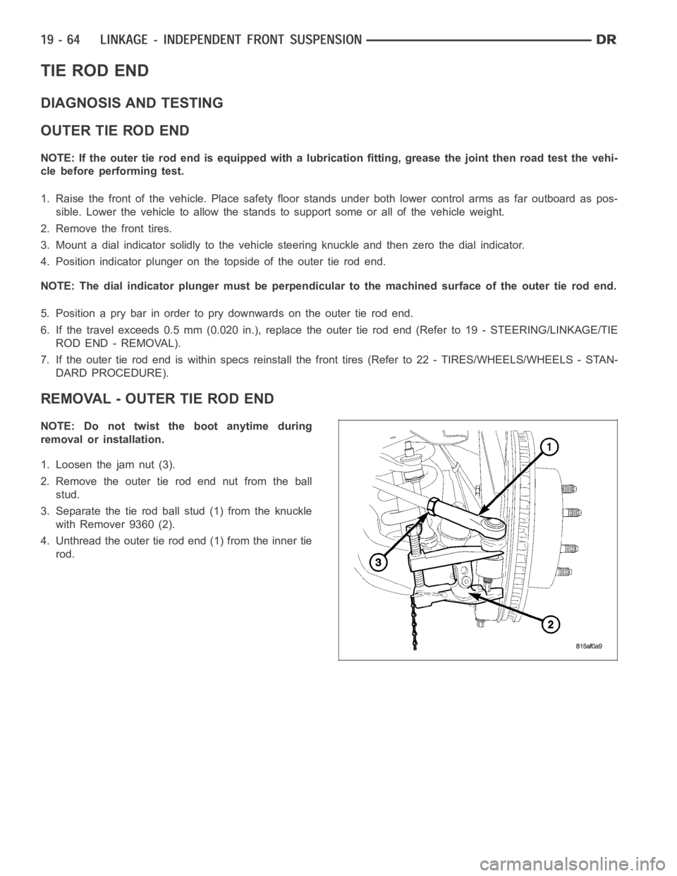
1. Loosen the jam nut (3).
2. Remove the outer tie rod end nut from the ball
stud.
3. Separate the tie rod ball stud (1) from the knuckle
with Remover 9360 (2).
4. Unthread the outer tie rod end (1) from the inner tie
rod.
Page 2470 of 5267
INSTALLATION - OUTER TIE ROD END
NOTE: Do not twist the boot at anytime during
removal or installation.
1. Thread the outer tie rod end (3) onto the inner tie
rod (2), to it’s original position.
2. Install the outer tie rod end (3) into the steering
knuckle.
3. Tighten the ball stud nut on the ball stud to 61 Nꞏm
(45 ft. lbs.) then an additional 90°.
4. Set wheel toe pattern, (Refer to 2 - SUSPENSION/
WHEEL ALIGNMENT - STANDARD PROCE-
DURE).
5. Tighten jam nut (1) to 127 Nꞏm (94 ft. lbs.).
Page 2525 of 5267
REMOVAL
1. With vehicle in neutral, position vehicle on hoist.
2. Disconnect battery negative cable.
3. Remove shift boot bezel screws and slide boot
upward on shift lever extension.
4. Remove shift lever extension from the shift tower
and lever assembly.
5. Remove 4WD shift boot if equipped.
6. Remove skid plate, if equipped.
7. Remove drain plug (1) from transmission (2) and
drain fluid.
8. Mark transmission flange (1) and propeller shaft (2)
for installation reference before removing propeller
shaft. If 4x4 equipped mark transfer case and front
propeller shaft before removing shaft.
Page 2529 of 5267
DISASSEMBLY
1. Set transmission on rear housing.
2. Remove shift tower bolts (1) and shift tower (2).
3. Pry off shift tower boot (1) with a screw driver (2).
Page 2578 of 5267
7. Apply Mopar™ Gasket Maker to the rear housing
sealing surface.
8. Install front housing (1) onto the rear housing (2).
9. Install housing bolts and tighten to 58 Nꞏm (43 ft.
lbs.).
10. Install 5-6 shift fork pins (1) into housing and
tighten to 58 Nꞏm (43 ft. lbs.).
11. Push shift tower boot (1) onto shift tower (2).