Page 2583 of 5267

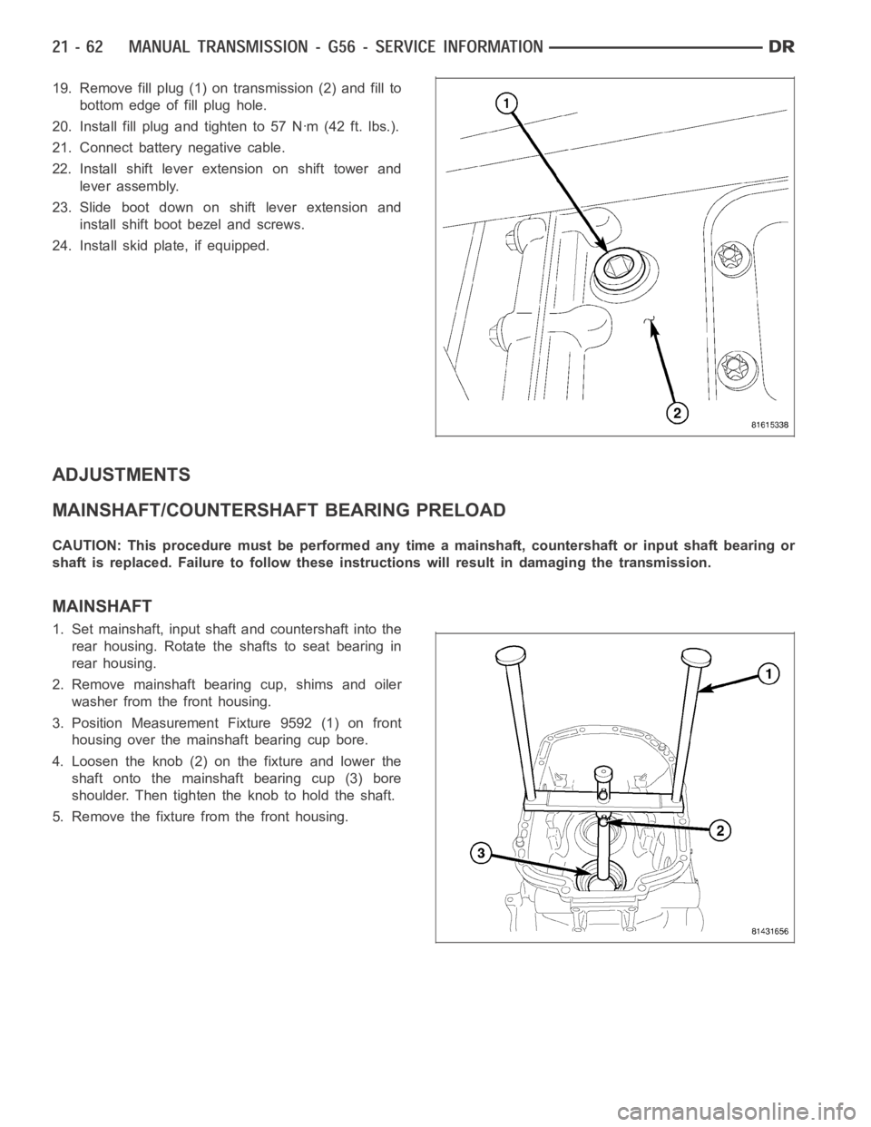
19. Remove fill plug (1) on transmission (2) and fill to
bottom edge of fill plug hole.
20. Install fill plug and tighten to 57 Nꞏm (42 ft. lbs.).
21. Connect battery negative cable.
22. Install shift lever extension on shift tower and
lever assembly.
23. Slide boot down on shift lever extension and
install shift boot bezel and screws.
24. Install skid plate, if equipped.
ADJUSTMENTS
MAINSHAFT/COUNTERSHAFT BEARING PRELOAD
CAUTION: This procedure must be performed any time a mainshaft, countershaft or input shaft bearing or
shaft is replaced. Failure to follow these instructions will result in damaging the transmission.
MAINSHAFT
1. Set mainshaft, input shaft and countershaft into the
rear housing. Rotate the shafts to seat bearing in
rear housing.
2. Remove mainshaft bearing cup, shims and oiler
washer from the front housing.
3. Position Measurement Fixture 9592 (1) on front
housing over the mainshaft bearing cup bore.
4. Loosen the knob (2) on the fixture and lower the
shaft onto the mainshaft bearing cup (3) bore
shoulder. Then tighten the knob to hold the shaft.
5. Remove the fixture from the front housing.
Page 2593 of 5267
4. Remove fill plug (1) from side of transmission (2).
5. Fill transmission even with the bottom of the fill
hole.
6. Install fill plug and tighten to 50 Nꞏm (37 ft. lbs.).
REMOVAL
1. With vehicle in neutral, position vehicle on hoist.
2. Disconnect battery negative cable.
3. Remove shift boot bezel screws and slide boot
upward on shift lever extension.
4. Remove shift lever extension from the shift tower
and lever assembly.
5. Remove 4WD shift boot if equipped and remove
floor console.
6. Remove skid plate, if equipped.
7. Remove drain plug (1) from rear housing (2) and
drain fluid.
8. Mark propeller shaft/shafts and companion flange
yoke/yokes for installation reference and remove
propeller shaft/shafts.
9. Disconnect harness from clips on transmission
housing.
10. Remove transfer case linkage if equipped.
11. Remove transfer case mounting nuts and remove
transfer case if equipped.
12. Remove slave cylinder (2) mounting nut (1) and
remove cylinder.
Page 4088 of 5267
3. Remove the front propeller shaft seal boot (1)
retaining clamp (2).
4. Remove the front propeller shaft seal boot (1).
5. Remove the front output shaft seal slinger (1) by
bending (2) the slinger ears away from the transfer
case.
Page 4115 of 5267

SEAL BOOT
1. Install the front output shaft seal slinger with Oil Slinger Installer 8840. Install the slinger onto the shaft until the
tool contacts the rear of the output shaft.
2. Install a new seal boot clamp onto the seal boot.
3. Install the seal boot and clamp onto the slinger hub and tighten the clampwith Crimp Tool C-4975-A.
REAR EXTENSION
1. Install new seal in rear extension housing seal with
Seal Installer D-163 and universal Handle C-4171..
2. Apply bead of Mopar
Gasket Maker, or equivalent,
to mating surface of rear extension housing. Keep
sealer bead width to maximum of 3/16 inch. Do not
use excessive amount of sealer as excess could
be displaced into output bearing.
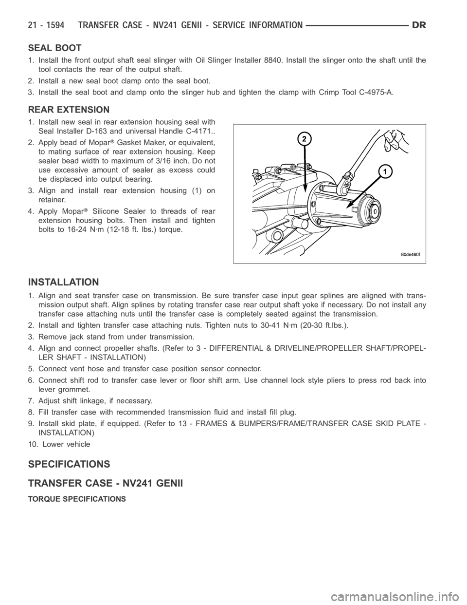
3. Align and install rear extension housing (1) on
retainer.
4. Apply Mopar
Silicone Sealer to threads of rear
extension housing bolts. Then install and tighten
bolts to 16-24 Nꞏm (12-18 ft. lbs.) torque.
INSTALLATION
1. Align and seat transfer case on transmission. Be sure transfer case input gear splines are aligned with trans-
mission output shaft. Align splines by rotating transfer case rear outputshaft yoke if necessary. Do not install any
transfer case attaching nuts until the transfer case is completely seatedagainst the transmission.
2. Install and tighten transfer case attaching nuts. Tighten nuts to 30-41Nꞏm (20-30 ft.lbs.).
3. Remove jack stand from under transmission.
4. Align and connect propeller shafts. (Refer to 3 - DIFFERENTIAL & DRIVELINE/PROPELLER SHAFT/PROPEL-
LER SHAFT - INSTALLATION)
5. Connect vent hose and transfer case position sensor connector.
6. Connect shift rod to transfer case lever or floor shift arm. Use channel lock style pliers to press rod back into
lever grommet.
7. Adjust shift linkage, if necessary.
8. Fill transfer case with recommended transmission fluid and install fillplug.
9. Install skid plate, if equipped. (Refer to 13 - FRAMES & BUMPERS/FRAME/TRANSFER CASE SKID PLATE -
INSTALLATION)
10. Lower vehicle
SPECIFICATIONS
TRANSFER CASE - NV241 GENII
TORQUE SPECIFICATIONS
Page 4121 of 5267
FRONT OUTPUT SHAFT SEAL
REMOVAL
1. Remove the front propeller shaft (Refer to 3 - DIF-
FERENTIAL & DRIVELINE/PROPELLER SHAFT/
PROPELLER SHAFT - REMOVAL).
2. Remove the front propeller shaft seal boot (1)
retaining clamp (2).
3. Remove the front propeller shaft seal boot (1).
4. Remove the front output shaft seal slinger (1) by
bending (2) the slinger ears away from the transfer
case.
Page 4122 of 5267
5. Using a suitable pry tool (2), remove the slinger (1)
from the output shaft using care not to damage the
shaft.
6. Using a screw and a slide hammer, remove the
front output shaft seal.
INSTALLATION
1. Install the new front output shaft seal with Seal Installer MB991168A.
2. Install the front output shaft seal slinger with Oil Slinger Installer 8840. Install the slinger onto the shaft until the
tool contacts the rear of the output shaft.
3. Install a new seal boot clamp onto the seal boot.
4. Install the seal boot and clamp onto the slinger hub and tighten the clampwith Crimp Tool C-4975-A.
5. Install front propeller shaft (Refer to 3 - DIFFERENTIAL & DRIVELINE/PROPELLER SHAFT/PROPELLER
SHAFT - INSTALLATION).
Page 4123 of 5267
LEVER-SHIFT
REMOVAL
1. Shift transfer case into 2H.
2. Raise and support the vehicle.
3. Loosen adjusting trunnion lock bolt and slide shift rod out of trunnion.If rod lacks enough travel to come out of
trunnion, push trunnion out of shift lever.
4. Lower vehicle.
5. Remove transfer case shifter knob cap.
6. Remove nut holding shifter knob (2) to shift lever.
7. Remove shifter knob.
8. Remove the shift boot from the shifter console.
9. Remove the bolts securing the shifter mechanism to the floor pan.
10. Separate shift lever mechanism from the vehicle.
Transfer Case Shifter
1 - SHIFTER BOOT 4 - SHIFTER MECHANISM
2-SHIFTERKNOB 5-ALIGNMENTPIN
3 - SHIFTER CONSOLE 6 - TRANSFER CASE
Page 4124 of 5267

INSTALLATION
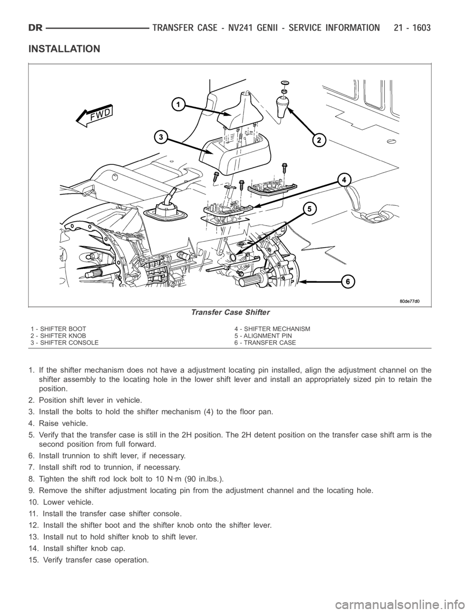
1. If the shifter mechanism does not have a adjustment locating pin installed, align the adjustment channel on the
shifter assembly to the locating hole in the lower shift lever and install an appropriately sized pin to retain the
position.
2. Position shift lever in vehicle.
3. Install the bolts to hold the shifter mechanism (4) to the floor pan.
4. Raise vehicle.
5. Verify that the transfer case is still in the 2H position. The 2H detent position on the transfer case shift arm is the
second position from full forward.
6. Install trunnion to shift lever, if necessary.
7. Install shift rod to trunnion, if necessary.
8. Tighten the shift rod lock bolt to 10 Nꞏm (90 in.lbs.).
9. Remove the shifter adjustment locating pin from the adjustment channeland the locating hole.
10. Lower vehicle.
11. Install the transfer case shifter console.
12. Install the shifter boot and the shifter knob onto the shifter lever.
13. Install nut to hold shifter knob to shift lever.
14. Install shifter knob cap.
15. Verify transfer case operation.
Transfer Case Shifter
1 - SHIFTER BOOT 4 - SHIFTER MECHANISM
2-SHIFTERKNOB 5-ALIGNMENTPIN
3 - SHIFTER CONSOLE 6 - TRANSFER CASE