Page 4264 of 5267

page page
TRANSFER CASE - NV273 - SERVICE
INFORMATION
DESCRIPTION ............................. 1744
OPERATION ............................... 1744
DIAGNOSIS AND TESTING - TRANSFER
CASE - NV273 ............................ 1745
REMOVAL ................................. 1746
DISASSEMBLY ............................. 1746
CLEANING ................................. 1760
INSPECTION ............................... 1760
ASSEMBLY . ............................... 1763
INSTALLATION ............................. 1780
SPECIFICATIONS
TRANSFER CASE - NV273 ................ 1781
SPECIAL TOOLS
TRANSFER CASE NV271/NV273 ........... 1782
BOOT-EXTENSION HOUSING SEAL AND DUST
REMOVAL ................................. 1784INSTALLATION ............................. 1784
FLUID
STANDARD PROCEDURE - FLUID DRAIN AND
REFILL ................................... 1785
SEAL-FRONT OUTPUT SHAFT
REMOVAL ................................. 1786
INSTALLATION ............................. 1786
SENSOR-MODE
DESCRIPTION ............................. 1787
OPERATION ............................... 1787
SWITCH-SELECTOR
DESCRIPTION ............................. 1789
OPERATION ............................... 1789
MOTOR-SHIFT
DESCRIPTION ............................. 1791
OPERATION ............................... 1791
REMOVAL ................................. 1791
INSTALLATION ............................. 1791
Page 4268 of 5267
5. Use a suitable chisel or pry tool to remove the rear
extension housing (1) dust boot (2).
6. Use a suitable chisel or pry tool to remove the rear
extension housing seal.
7. Remove rear extension (1) bolts (2).
8. Remove rear extension housing (2). Tap extension
once or twice with a plastic mallet to break sealer
bead and loosen it.
Page 4301 of 5267

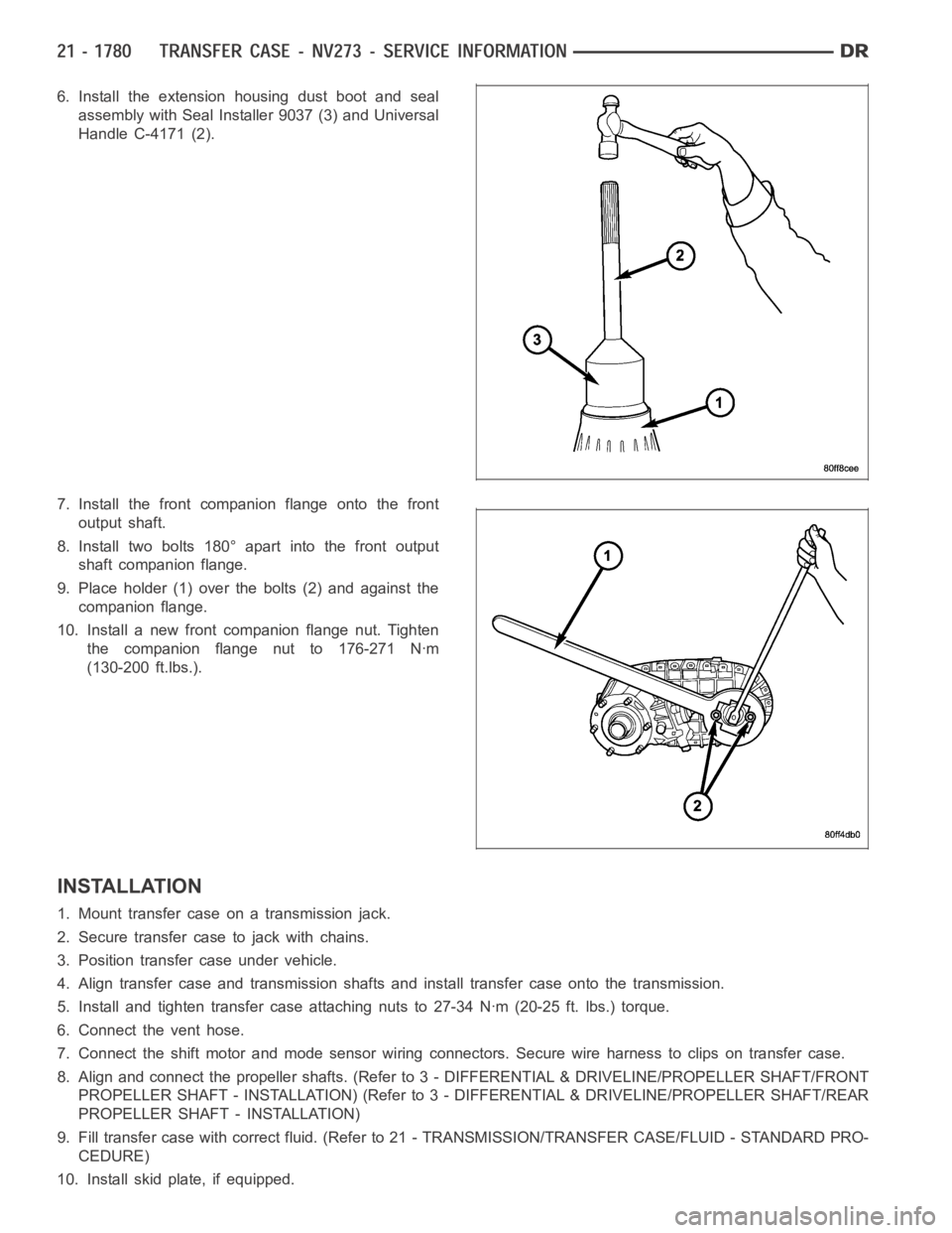
6. Install the extension housing dust boot and seal
assembly with Seal Installer 9037 (3) and Universal
Handle C-4171 (2).
7. Install the front companion flange onto the front
output shaft.
8. Install two bolts 180° apart into the front output
shaft companion flange.
9. Place holder (1) over the bolts (2) and against the
companion flange.
10. Install a new front companion flange nut. Tighten
the companion flange nut to 176-271 Nꞏm
(130-200 ft.lbs.).
INSTALLATION
1. Mount transfer case on a transmission jack.
2. Secure transfer case to jack with chains.
3. Position transfer case under vehicle.
4. Align transfer case and transmission shafts and install transfer case onto the transmission.
5. Install and tighten transfer case attaching nuts to 27-34 Nꞏm (20-25 ft.lbs.) torque.
6. Connect the vent hose.
7. Connect the shift motor and mode sensor wiring connectors. Secure wire harness to clips on transfer case.
8. Align and connect the propeller shafts. (Refer to 3 - DIFFERENTIAL & DRIVELINE/PROPELLER SHAFT/FRONT
PROPELLER SHAFT - INSTALLATION) (Refer to 3 - DIFFERENTIAL & DRIVELINE/PROPELLER SHAFT/REAR
PROPELLER SHAFT - INSTALLATION)
9. Fill transfer case with correct fluid. (Refer to 21 - TRANSMISSION/TRANSFER CASE/FLUID - STANDARD PRO-
CEDURE)
10. Install skid plate, if equipped.
Page 4305 of 5267
BOOT-EXTENSION HOUSING SEAL AND DUST
REMOVAL
1. Raise and support vehicle.
2. Remove rear propeller shaft. (Refer to 3 - DIFFER-
ENTIAL & DRIVELINE/PROPELLER SHAFT/PRO-
PELLER SHAFT - REMOVAL)
3. Use a suitable chisel or pry tool to remove the rear
extension housing dust boot (2).
4. Use a suitable chisel or pry tool to remove the rear
extension housing seal.
INSTALLATION
1. Clean fluid residue from sealing surface and
inspect for defects.
2. Install the extension housing dust boot and seal
assembly with Seal Installer 9037 (3) and Universal
Handle C-4171 (2).
3. Install propeller shaft. (Refer to 3 - DIFFERENTIAL
& DRIVELINE/PROPELLER SHAFT/PROPELLER
SHAFT - INSTALLATION)
4. Verify proper transfer case fluid level.
5. Lower vehicle.
Page 4513 of 5267

page page
INTERIOR
CAUTION ................................... 177
4WD FLOOR SHIFT BOOT
REMOVAL ................................... 178
INSTALLATION .............................. 178
A-PILLAR TRIM/GRAB HANDLE
REMOVAL ................................... 180
INSTALLATION .............................. 180
B-PILLAR GRAB HANDLE
REMOVAL ................................... 181
INSTALLATION .............................. 181
B-PILLAR LOWER TRIM
REMOVAL ................................... 182
INSTALLATION .............................. 183
B-PILLAR UPPER TRIM
REMOVAL ................................... 184
INSTALLATION .............................. 185
C-PILLAR LOWER TRIM
REMOVAL ................................... 187
INSTALLATION .............................. 187
C-PILLAR UPPER TRIM
REMOVAL ................................... 188
INSTALLATION .............................. 188
CARPETS AND FLOOR MATS
REMOVAL ................................... 189
INSTALLATION .............................. 191
COAT HOOK
REMOVAL ................................... 194
INSTALLATION .............................. 194
COWL TRIM
REMOVAL ................................... 195INSTALLATION .............................. 195
FLOOR CONSOLE
REMOVAL ................................... 196
INSTALLATION .............................. 199
HEADLINER
REMOVAL ................................... 202
INSTALLATION .............................. 202
LOAD FLOOR
REMOVAL ................................... 204
INSTALLATION .............................. 205
REAR CAB BACK PANEL TRIM
REMOVAL ................................... 206
INSTALLATION .............................. 207
REAR DOOR SILL TRIM COVER
REMOVAL ................................... 209
INSTALLATION .............................. 209
REAR VIEW MIRROR
REMOVAL ................................... 210
INSTALLATION
INSTALLATION ............................ 210
REAR VIEW MIRROR MOUNTING BRACKET . 210
SUN VISOR
REMOVAL ................................... 212
INSTALLATION .............................. 212
SUN VISOR SUPPORT
REMOVAL ................................... 213
INSTALLATION .............................. 213
BODY VENT
REMOVAL ................................... 214
INSTALLATION .............................. 214
Page 4515 of 5267
4WD FLOOR SHIFT BOOT
REMOVAL
1. Using a small flat-bladed tool, remove the insert (2)
from the top of the shift knob (1).
2. Remove the nut (3) that secures the shift knob to
the gear shift lever.
3. Remove the gear shift knob (2).
4. Using a trim stick C-4755 or equivalent, disengage
the retaining tabs that secure the gear shift boot (3)
to the floor console (1) and remove the boot.
INSTALLATION
1. Position the gear shift boot (3) over the gear shift
lever.
2. Engage the retaining tabs that secure the gear shift
boot to the floor console (1).
3. Install the shift knob (2) over the gear shift lever.
Page 4533 of 5267
FLOOR CONSOLE
REMOVAL
Mini Floor Console
1. If equipped, remove the 4WD gear shift boot (Refer
to 23 - BODY/INTERIOR/4WD FLOOR SHIFT
BOOT - REMOVAL).
2. If equipped with a manual transmission, remove
the transmission gear shift lever extension.
3. Remove the console inserts, if equipped.
4. Remove the bolts (2) that secure the rear console
(1) to the floor panel.
5. Lift up the rear of the floor console to clear the
gear shift lever, if equipped.
Page 4537 of 5267
3. Install the bolts (2) that secure the rear console (1)
to the floor panel.
4. Install the inserts.
5. Install the gear shift lever extension.
6. Install the 4WD gear shift boot.