Page 4125 of 5267
ADJUSTMENTS
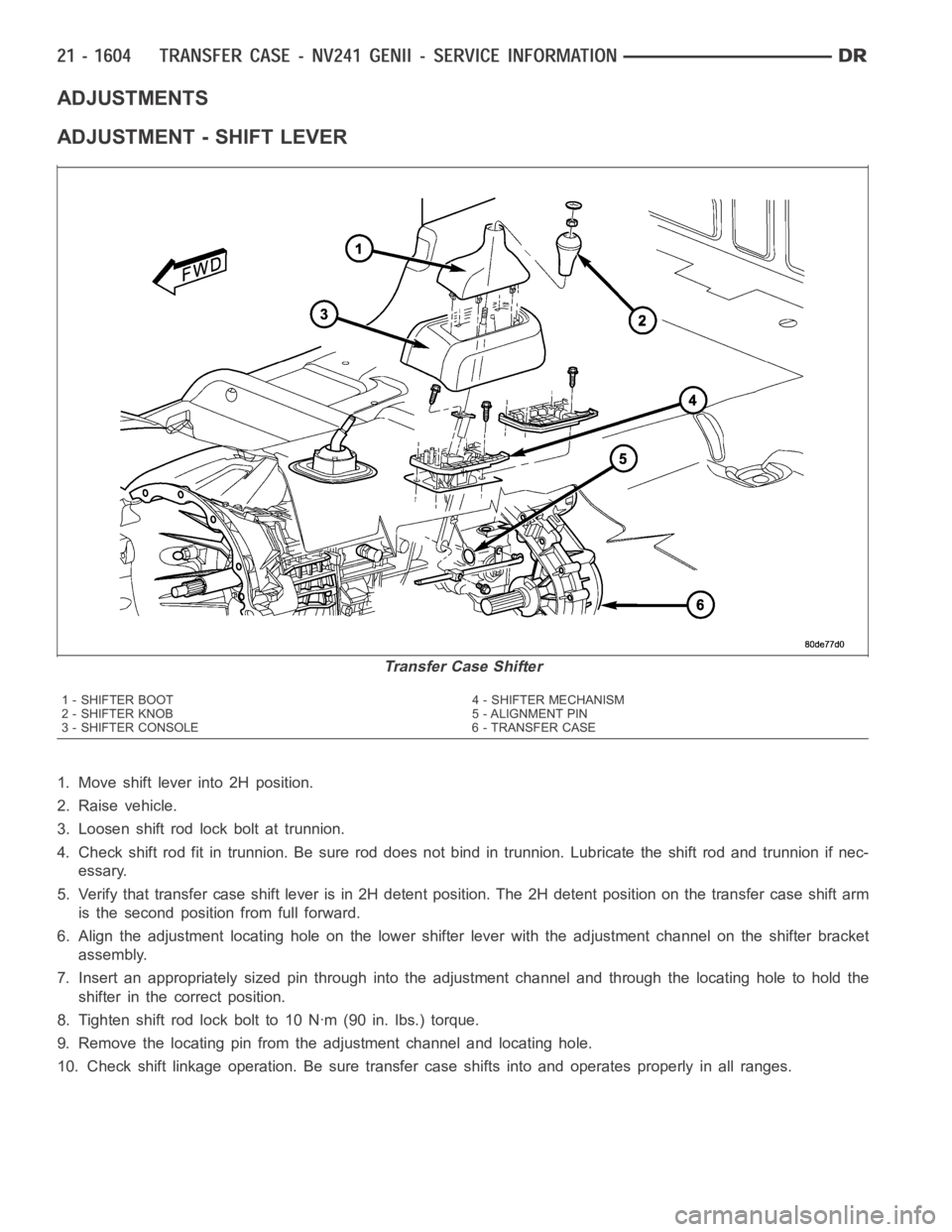
ADJUSTMENT - SHIFT LEVER
1. Move shift lever into 2H position.
2. Raise vehicle.
3. Loosen shift rod lock bolt at trunnion.
4. Check shift rod fit in trunnion. Be sure rod does not bind in trunnion. Lubricate the shift rod and trunnion if nec-
essary.
5. Verify that transfer case shift lever is in 2H detent position. The 2H detent position on the transfer case shift arm
is the second position from full forward.
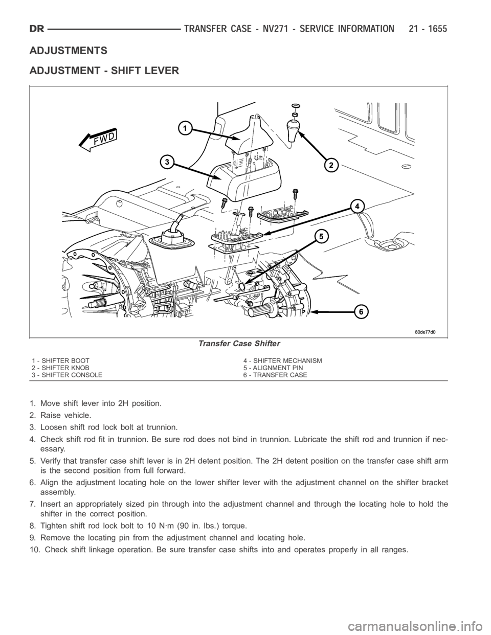
6. Align the adjustment locating hole on the lower shifter lever with the adjustment channel on the shifter bracket
assembly.
7. Insert an appropriately sized pin through into the adjustment channel and through the locating hole to hold the
shifter in the correct position.
8. Tighten shift rod lock bolt to 10 Nꞏm (90 in. lbs.) torque.
9. Remove the locating pin from the adjustment channel and locating hole.
10. Check shift linkage operation. Be sure transfer case shifts into and operates properly in all ranges.
Transfer Case Shifter
1 - SHIFTER BOOT 4 - SHIFTER MECHANISM
2-SHIFTERKNOB 5-ALIGNMENTPIN
3 - SHIFTER CONSOLE 6 - TRANSFER CASE
Page 4126 of 5267
page page
TRANSFER CASE - NV271 - SERVICE
INFORMATION
DESCRIPTION ............................. 1606
OPERATION ............................... 1606
DIAGNOSIS AND TESTING - TRANSFER
CASE - NV271 ............................ 1607
REMOVAL ................................. 1608
DISASSEMBLY ............................. 1608
CLEANING ................................. 1623
INSPECTION ............................... 1623
ASSEMBLY . ............................... 1626
INSTALLATION ............................. 1644
SPECIFICATIONS
TRANSFER CASE - NV271 ................ 1645
SPECIAL TOOLS
TRANSFER CASE NV271/NV273 ........... 1646
BOOT-EXTENSION HOUSING SEAL AND DUST
REMOVAL ................................. 1648INSTALLATION ............................. 1648
FLUID
STANDARD PROCEDURE - FLUID DRAIN AND
REFILL ................................... 1649
SEAL-FRONT OUTPUT SHAFT
REMOVAL ................................. 1650
INSTALLATION ............................. 1650
SENSOR-POSITION
DESCRIPTION ............................. 1651
OPERATION ............................... 1651
REMOVAL ................................. 1651
INSTALLATION ............................. 1652
LEVER-SHIFT
REMOVAL ................................. 1653
INSTALLATION ............................. 1654
ADJUSTMENTS
ADJUSTMENT - SHIFT LEVER............. 1655
Page 4130 of 5267
COMPANION FLANGE AND EXTENSION HOUSING
1. Install two bolts 180° apart into the front output
shaft companion flange.
2. Place holder (1) over the bolts (2) and against the
companion flange.
3. Remove and discard the front companion flange
nut.
4. Remove the companion flange from the front out-
put shaft. It may be necessary to use Pinion
Flange Remover 8992 to remove the companion
flange.
5. Use a suitable chisel or pry tool to remove the rear
extension housing (1) dust boot (2).
6. Use a suitable chisel or pry tool to remove the rear
extension housing seal.
Page 4165 of 5267
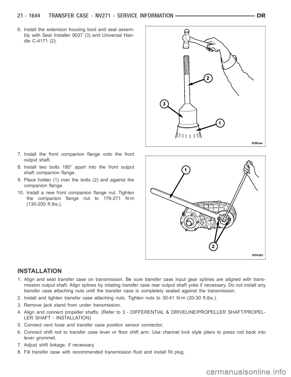
6. Install the extension housing boot and seal assem-
bly with Seal Installer 9037 (3) and Universal Han-
dle C-4171 (2).
7. Install the front companion flange onto the front
output shaft.
8. Install two bolts 180° apart into the front output
shaft companion flange.
9. Place holder (1) over the bolts (2) and against the
companion flange.
10. Install a new front companion flange nut. Tighten
the companion flange nut to 176-271 Nꞏm
(130-200 ft.lbs.).
INSTALLATION
1. Align and seat transfer case on transmission. Be sure transfer case input gear splines are aligned with trans-
mission output shaft. Align splines by rotating transfer case rear outputshaft yoke if necessary. Do not install any
transfer case attaching nuts until the transfer case is completely seatedagainst the transmission.
2. Install and tighten transfer case attaching nuts. Tighten nuts to 30-41Nꞏm (20-30 ft.lbs.).
3. Remove jack stand from under transmission.
4. Align and connect propeller shafts. (Refer to 3 - DIFFERENTIAL & DRIVELINE/PROPELLER SHAFT/PROPEL-
LER SHAFT - INSTALLATION)
5. Connect vent hose and transfer case position sensor connector.
6. Connect shift rod to transfer case lever or floor shift arm. Use channel lock style pliers to press rod back into
lever grommet.
7. Adjust shift linkage, if necessary.
8. Fill transfer case with recommended transmission fluid and install fillplug.
Page 4169 of 5267
BOOT-EXTENSION HOUSING SEAL AND DUST
REMOVAL
1. Raise and support vehicle.
2. Remove rear propeller shaft. (Refer to 3 - DIFFER-
ENTIAL & DRIVELINE/PROPELLER SHAFT/PRO-
PELLER SHAFT - REMOVAL)
3. Use a suitable chisel or pry tool to remove the rear
extension housing dust boot (2).
4. Use a suitable chisel or pry tool to remove the rear
extension housing seal.
INSTALLATION
1. Clean fluid residue from sealing surface and
inspect for defects.
2. Install the extension housing dust boot and seal
assembly with Seal Installer 9037 (3) and Universal
Handle C-4171 (2).
3. Install propeller shaft. (Refer to 3 - DIFFERENTIAL
& DRIVELINE/PROPELLER SHAFT/PROPELLER
SHAFT - INSTALLATION)
4. Verify proper transfer case fluid level.
5. Lower vehicle.
Page 4174 of 5267
LEVER-SHIFT
REMOVAL
1. Shift transfer case into 2H.
2. Raise and support the vehicle.
3. Loosen adjusting trunnion lock bolt and slide shift rod out of trunnion.If rod lacks enough travel to come out of
trunnion, push trunnion out of shift lever.
4. Lower vehicle.
5. Remove transfer case shifter knob cap.
6. Remove nut holding shifter knob (2) to shift lever.
7. Remove shifter knob.
8. Remove the shift boot from the shifter console.
9. Remove the bolts securing the shifter mechanism to the floor pan.
10. Separate shift lever mechanism from the vehicle.
Transfer Case Shifter
1 - SHIFTER BOOT 4 - SHIFTER MECHANISM
2-SHIFTERKNOB 5-ALIGNMENTPIN
3 - SHIFTER CONSOLE 6 - TRANSFER CASE
Page 4175 of 5267
INSTALLATION
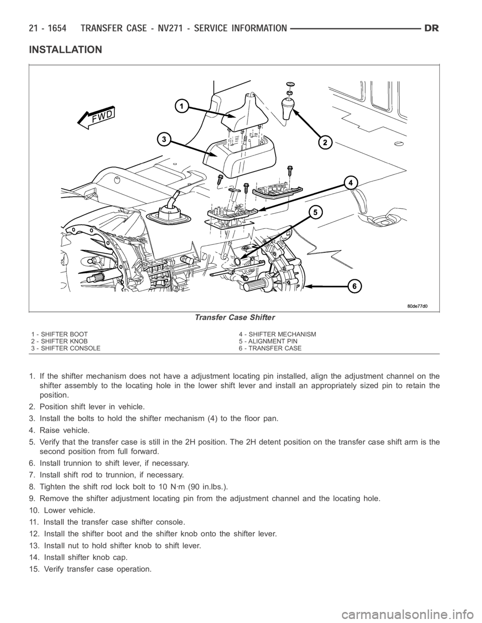
1. If the shifter mechanism does not have a adjustment locating pin installed, align the adjustment channel on the
shifter assembly to the locating hole in the lower shift lever and install an appropriately sized pin to retain the
position.
2. Position shift lever in vehicle.
3. Install the bolts to hold the shifter mechanism (4) to the floor pan.
4. Raise vehicle.
5. Verify that the transfer case is still in the 2H position. The 2H detent position on the transfer case shift arm is the
second position from full forward.
6. Install trunnion to shift lever, if necessary.
7. Install shift rod to trunnion, if necessary.
8. Tighten the shift rod lock bolt to 10 Nꞏm (90 in.lbs.).
9. Remove the shifter adjustment locating pin from the adjustment channeland the locating hole.
10. Lower vehicle.
11. Install the transfer case shifter console.
12. Install the shifter boot and the shifter knob onto the shifter lever.
13. Install nut to hold shifter knob to shift lever.
14. Install shifter knob cap.
15. Verify transfer case operation.
Transfer Case Shifter
1 - SHIFTER BOOT 4 - SHIFTER MECHANISM
2-SHIFTERKNOB 5-ALIGNMENTPIN
3 - SHIFTER CONSOLE 6 - TRANSFER CASE
Page 4176 of 5267
ADJUSTMENTS
ADJUSTMENT - SHIFT LEVER
1. Move shift lever into 2H position.
2. Raise vehicle.
3. Loosen shift rod lock bolt at trunnion.
4. Check shift rod fit in trunnion. Be sure rod does not bind in trunnion. Lubricate the shift rod and trunnion if nec-
essary.
5. Verify that transfer case shift lever is in 2H detent position. The 2H detent position on the transfer case shift arm
is the second position from full forward.
6. Align the adjustment locating hole on the lower shifter lever with the adjustment channel on the shifter bracket
assembly.
7. Insert an appropriately sized pin through into the adjustment channel and through the locating hole to hold the
shifter in the correct position.
8. Tighten shift rod lock bolt to 10 Nꞏm (90 in. lbs.) torque.
9. Remove the locating pin from the adjustment channel and locating hole.
10. Check shift linkage operation. Be sure transfer case shifts into and operates properly in all ranges.
Transfer Case Shifter
1 - SHIFTER BOOT 4 - SHIFTER MECHANISM
2-SHIFTERKNOB 5-ALIGNMENTPIN
3 - SHIFTER CONSOLE 6 - TRANSFER CASE