2006 DODGE RAM SRT-10 center console
[x] Cancel search: center consolePage 4512 of 5267
STORAGE BIN
REMOVAL
WARNING: On vehicles equipped with airbags, disable the airbag system before attempting any steering
wheel, steering column, seat belt tensioner, or instrument panel component diagnosis or service. Discon-
nect and isolate the battery negative (ground) cable, then wait two minutes for the airbag system capacitor
to discharge before performing further diagnosis or service. This is the only sure way to disable the airbag
system. Failure to take the proper precautions could result in accidentalairbag deployment and possible
personal injury or death.
NOTE: A storage bin replaces the cup holder in
the instrument panel when the vehicle is equipped
with a floor console.
1. Remove the instrument panel center bezel (Refer
to 23 - BODY/INSTRUMENT PANEL/INSTRU-
MENT PANEL CENTER BEZEL - REMOVAL).
2. Removethefloorconsole(Referto23-BODY/IN-
TERIOR/FLOOR CONSOLE - REMOVAL).
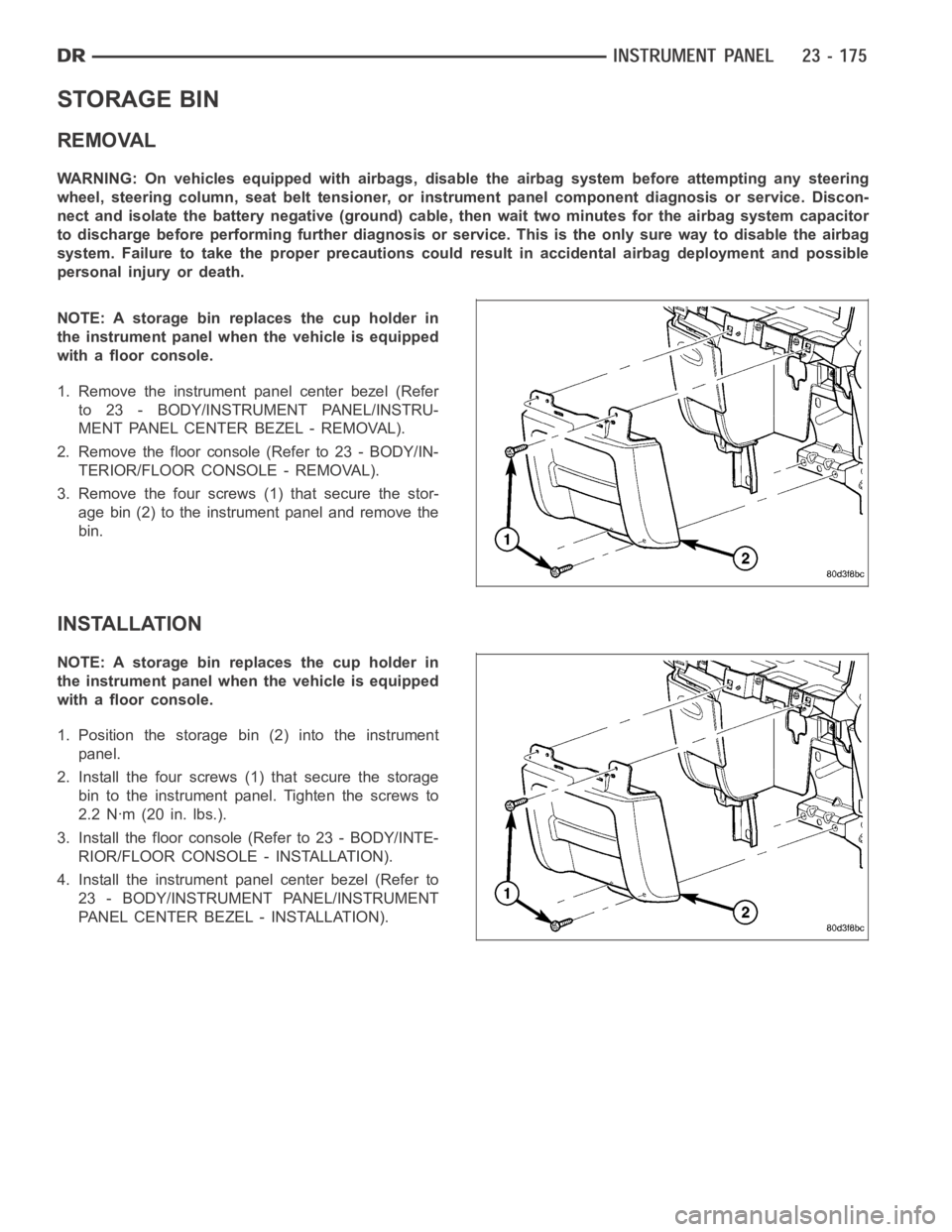
3. Remove the four screws (1) that secure the stor-
age bin (2) to the instrument panel and remove the
bin.
INSTALLATION
NOTE: A storage bin replaces the cup holder in
the instrument panel when the vehicle is equipped
with a floor console.
1. Position the storage bin (2) into the instrument
panel.
2. Install the four screws (1) that secure the storage
bin to the instrument panel. Tighten the screws to
2.2 Nꞏm (20 in. lbs.).
3. Install the floor console (Refer to 23 - BODY/INTE-
RIOR/FLOOR CONSOLE - INSTALLATION).
4. Install the instrument panel center bezel (Refer to
23 - BODY/INSTRUMENT PANEL/INSTRUMENT
PANEL CENTER BEZEL - INSTALLATION).
Page 4536 of 5267
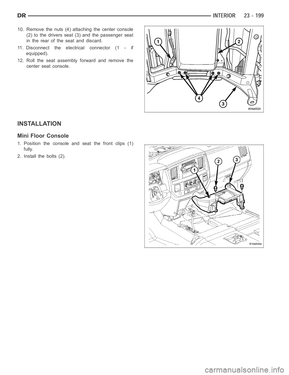
10. Remove the nuts (4) attaching the center console
(2) to the drivers seat (3) and the passenger seat
in the rear of the seat and discard.
11. Disconnect the electrical connector (1 - if
equipped).
12. Roll the seat assembly forward and remove the
center seat console.
INSTALLATION
Mini Floor Console
1. Position the console and seat the front clips (1)
fully.
2. Install the bolts (2).
Page 4538 of 5267
Full Floor Console
1. Before proceeding with the following repair proce-
dure, review all warnings and cautions. (Refer to
23 - BODY/SEATS - WARNING)
NOTE: Do not reuse the seat fasteners, always
replace with new ones.
2. Position the center seat console onto the front seat
assembly and roll the seat assembly back in the
vehicle.
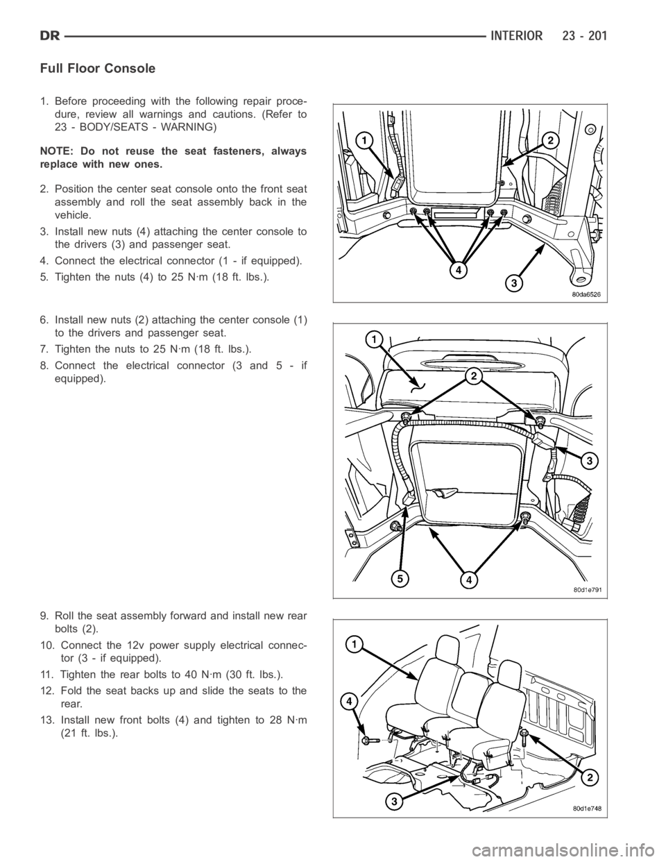
3. Install new nuts (4) attaching the center console to
the drivers (3) and passenger seat.
4. Connect the electrical connector (1 - if equipped).
5. Tighten the nuts (4) to 25 Nꞏm (18 ft. lbs.).
6. Install new nuts (2) attaching the center console (1)
to the drivers and passenger seat.
7. Tightenthenutsto25Nꞏm(18ft.lbs.).
8. Connect the electrical connector (3 and 5 - if
equipped).
9. Roll the seat assembly forward and install new rear
bolts (2).
10. Connect the 12v power supply electrical connec-
tor (3 - if equipped).
11. Tighten the rear bolts to 40 Nꞏm (30 ft. lbs.).
12. Fold the seat backs up and slide the seats to the
rear.
13. Install new front bolts (4) and tighten to 28 Nꞏm
(21 ft. lbs.).
Page 4539 of 5267
HEADLINER
REMOVAL
NOTE: Headliner for Quad Cab model shown. Reg-
ular cab similar.
1. Remove the A-pillar trim panels (Refer to 23 -
BODY/INTERIOR/A-PILLAR TRIM - REMOVAL).
2. Remove the upper B-pillar trim panels (Refer to 23
- BODY/INTERIOR/B-PILLAR UPPER TRIM -
REMOVAL).
3. On Quad Cab models, remove the upper C-pillar
trim panels (Refer to 23 - BODY/INTERIOR/C-PIL-
LAR TRIM - REMOVAL).
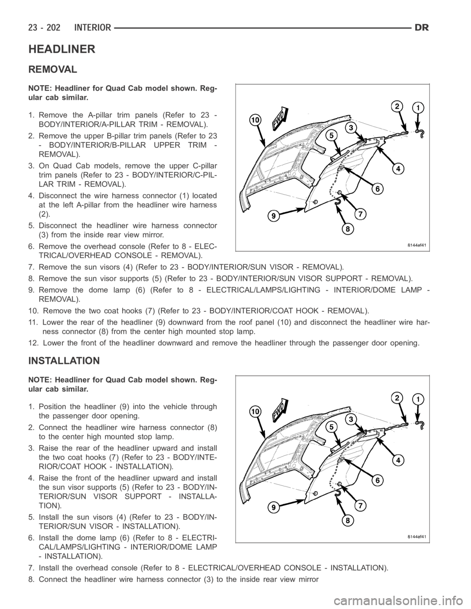
4. Disconnect the wire harness connector (1) located
at the left A-pillar from the headliner wire harness
(2).
5. Disconnect the headliner wire harness connector
(3) from the inside rear view mirror.
6. Remove the overhead console (Refer to 8 - ELEC-
TRICAL/OVERHEAD CONSOLE - REMOVAL).
7. Remove the sun visors (4) (Refer to 23 - BODY/INTERIOR/SUN VISOR - REMOVAL).
8. Remove the sun visor supports (5) (Refer to 23 - BODY/INTERIOR/SUN VISORSUPPORT - REMOVAL).
9. Remove the dome lamp (6) (Refer to 8 -ELECTRICAL/LAMPS/LIGHTING - INTERIOR/DOME LAMP -
REMOVAL).
10. Remove the two coat hooks (7) (Refer to 23 - BODY/INTERIOR/COAT HOOK - REMOVAL).
11. Lower the rear of the headliner (9) downward from the roof panel (10) anddisconnect the headliner wire har-
ness connector (8) from the center high mounted stop lamp.
12. Lower the front of the headliner downward and remove the headliner through the passenger door opening.
INSTALLATION
NOTE: Headliner for Quad Cab model shown. Reg-
ular cab similar.
1. Position the headliner (9) into the vehicle through
the passenger door opening.
2. Connect the headliner wire harness connector (8)
to the center high mounted stop lamp.
3. Raise the rear of the headliner upward and install
the two coat hooks (7) (Refer to 23 - BODY/INTE-
RIOR/COAT HOOK - INSTALLATION).
4. Raise the front of the headliner upward and install
the sun visor supports (5) (Refer to 23 - BODY/IN-
TERIOR/SUN VISOR SUPPORT - INSTALLA-
TION).
5. Install the sun visors (4) (Refer to 23 - BODY/IN-
TERIOR/SUN VISOR - INSTALLATION).
6. Install the dome lamp (6) (Refer to 8 - ELECTRI-
CAL/LAMPS/LIGHTING - INTERIOR/DOME LAMP
- INSTALLATION).
7. Install the overhead console (Refer to 8 - ELECTRICAL/OVERHEAD CONSOLE-INSTALLATION).
8. Connect the headliner wire harness connector (3) to the inside rear viewmirror
Page 4609 of 5267
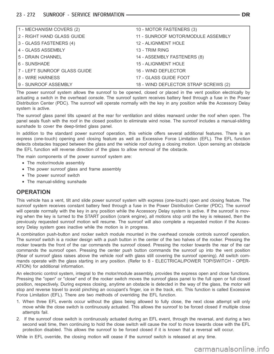
1 - MECHANISM COVERS (2) 10 - MOTOR FASTENERS (3)
2 - RIGHT HAND GLASS GUIDE 11 - SUNROOF MOTOR/MODULE ASSEMBLY
3 - GLASS FASTENERS (4) 12 - ALIGNMENT HOLE
4 - GLASS ASSEMBLY 13 - TRIM RING
5 - DRAIN CHANNEL 14 - ASSEMBLY FASTENERS (8)
6 - SUNSHADE 15 - ALIGNMENT HOLE
7 - LEFT SUNROOF GLASS GUIDE 16 - WIND DEFLECTOR
8 - WIRE HARNESS 17 - GLASS GUIDE FOOT
9 - SUNROOF ASSEMBLY 18 - WIND DEFLECTOR STRAP SCREWS (2)
The power sunroof system allows the sunroof to be opened, closed or placed in the vent position electrically by
actuating a switch in the overhead console. The sunroof system receives battery feed through a fuse in the Power
Distribution Center (PDC). The sunroof will operate normally with the keyin any position while the Accessory Delay
system is active.
The sunroof glass panel tilts upward at the rear for ventilation and slidesrearward under the roof when open. The
panel seals flush with the roof in the closed position to eliminate wind noise. The sunroof includes a manual-sliding
sunshade to cover the deep-tinted glass panel.
In addition to the standard power sunroof operation, this vehicle offers several additional features. There is an
express (one-touch) opening and closing feature as well as Excessive Force Limitation (EFL). The EFL function
detects obstacles trapped between the glass and the vehicle roof during a closing motion. Upon sensing an obstacle
the EFL function will reverse direction of the glass to allow removal of theobstacle.
The main components of thepower sunroof system are:
The motor/module assembly
The power sunroof glass and frame assembly
The power sunroof switch
The manual-sliding sunshade
OPERATION
This vehicle has a vent, tilt and slide power sunroof system with express (one-touch) open and closing feature. The
sunroof system receives constant battery feed through a fuse in the Power Distribution Center (PDC). The sunroof
will operate normally with the key in any position while the Accessory Delay system is active. If the sunroof is mov-
ing when the key is turned to the START position (crank engine), all motionsstop until the key is released, then the
previously requested sunroof motion will resume. The sunroof will also complete a requested motion if the Acces-
sory Delay system goes inactivewhile the motion is in progress.
A combination push-button and rocker switch module mounted in the overhead console controls sunroof operation.
The sunroof switch is a rocker design with a push button in the center of the two halves of the rocker. Pressing the
rocker towards the front of the car commands the sunroof closed. Pressing the rocker towards the rear of the car
commands the sunroof open. Pressing the center push button commands the sunroof up into the vent position
(Rear of sunroof glass raises above the vehicle roof with glass still covering the sunroof opening). All switch com-
mands operate with the glass startingin any position. (Refer to 8 - ELECTRICAL/POWER TOP/SWITCH - OPER-
ATION) for additional information.
An electronic control system, integralto the motor/module assembly, provides the express open and close functions.
Pressing the
openorcloseend of the rocker switch moves the sunroof glass panel to the full open or fullclosed
position, respectively. During express closing, anytime an obstacle is detected in the way of the glass, the motor will
stop and reverse travel to avoid pinching an occupant’s finger, ice in the track, etc. This function is called Excessive
Force Limitation (EFL). There are two methods of overriding the EFL function.
1. When three EFL events occur without the glass being allowed to fully close, the next close attempt will only
move while the close switch is continuously actuated. This allows the sunrooftobeforcedclosedifmultipleclose
attempts fail.
2. If the sunroof close switch is continuously actuated during an EFL event, through the reversal, and during a two
second wait time, then continuing to hold the close switch will cause the roof to move towards close with the EFL
protection disabled. This allows the sunroof to be forced closed if it is known that a reversal will occur.
While in EFL override, the closing motion will cease if the sunroof switch is released at any time.
Page 5097 of 5267
DUCT-FLOOR CONSOLE
REMOVAL
NOTE: Illustration shown with seat cushions
removed from view for clarity.
1. Removethefloorconsole(Referto23-BODY/IN-
TERIOR/FLOOR CONSOLE - REMOVAL).
2. Slide the floor console duct (1) rearward and first
disconnect it from the floor distribution duct (3)
located on the bottom of the HVAC housing (4), then disconnect the floor duct from the rear duct (33) located
below the center seat.
3. If required, remove the rear duct from the center seat support.
INSTALLATION
NOTE: Illustration shown with seat cushions
removed from view for clarity.
1. If removed, install the rear duct (2) to the bottom of
the center seat support. Make sure the duct is fully
engaged to the rear outlets.
2. Install the floor console duct (1) onto the rear duct
and then slide it forward and connect it to the floor distribution duct (3) located at the bottom of the HVAC hous-
ing (4). Make sure all ducts are fully to each other.
3. Install the floor console (Refer to 23 - BODY/INTERIOR/FLOOR CONSOLE - INSTALLATION).