2006 DODGE RAM SRT-10 remove seats
[x] Cancel search: remove seatsPage 1494 of 5267
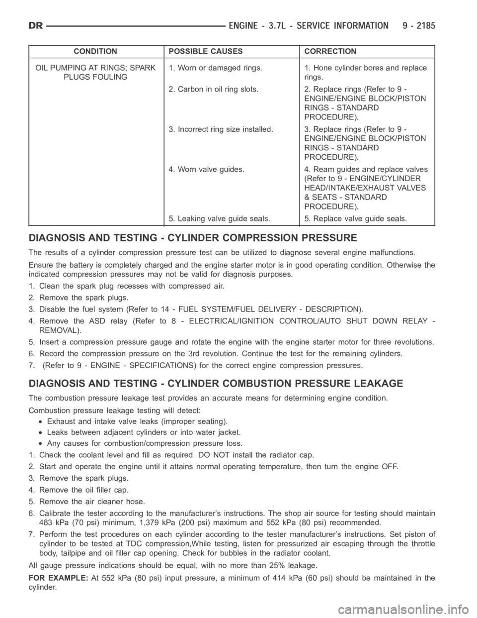
CONDITION POSSIBLE CAUSES CORRECTION
OIL PUMPING AT RINGS; SPARK
PLUGS FOULING1. Worn or damaged rings. 1. Hone cylinder bores and replace
rings.
2. Carbon in oil ring slots. 2. Replace rings (Refer to 9 -
ENGINE/ENGINE BLOCK/PISTON
RINGS - STANDARD
PROCEDURE).
3. Incorrect ring size installed. 3. Replace rings (Refer to 9 -
ENGINE/ENGINE BLOCK/PISTON
RINGS - STANDARD
PROCEDURE).
4. Worn valve guides. 4. Ream guides and replace valves
(Refer to 9 - ENGINE/CYLINDER
HEAD/INTAKE/EXHAUST VALVES
& SEATS - STANDARD
PROCEDURE).
5. Leaking valve guide seals. 5. Replace valve guide seals.
DIAGNOSIS AND TESTING - CYLINDER COMPRESSION PRESSURE
The results of a cylinder compressionpressure test can be utilized to diagnose several engine malfunctions.
Ensurethebatteryiscompletelychargedandtheenginestartermotorisingood operating condition. Otherwise the
indicated compression pressures may not be valid for diagnosis purposes.
1. Clean the spark plug recesses with compressed air.
2. Remove the spark plugs.
3. Disable the fuel system (Refer to 14 - FUEL SYSTEM/FUEL DELIVERY - DESCRIPTION).
4. Remove the ASD relay (Refer to 8 - ELECTRICAL/IGNITION CONTROL/AUTO SHUTDOWNRELAY-
REMOVAL).
5. Insert a compression pressure gauge and rotate the engine with the engine starter motor for three revolutions.
6. Record the compression pressure on the 3rd revolution. Continue the test for the remaining cylinders.
7. (Refer to 9 - ENGINE - SPECIFICATIONS) for the correct engine compression pressures.
DIAGNOSIS AND TESTING - CYLINDERCOMBUSTION PRESSURE LEAKAGE
The combustion pressure leakage test provides an accurate means for determining engine condition.
Combustion pressure leakage testing will detect:
Exhaust and intake valve leaks (improper seating).
Leaks between adjacent cylinders or into water jacket.
Any causes for combustion/compression pressure loss.
1. Check the coolant level and fill as required. DO NOT install the radiatorcap.
2. Start and operate the engine until it attains normal operating temperature, then turn the engine OFF.
3. Remove the spark plugs.
4. Remove the oil filler cap.
5. Remove the air cleaner hose.
6. Calibrate the tester according to the manufacturer’s instructions. The shop air source for testing should maintain
483 kPa (70 psi) minimum, 1,379 kPa (200 psi) maximum and 552 kPa (80 psi) recommended.
7. Perform the test procedures on each cylinder according to the tester manufacturer’s instructions. Set piston of
cylinder to be tested at TDC compression,While testing, listen for pressurized air escaping through the throttle
body, tailpipe and oil filler cap opening. Check for bubbles in the radiator coolant.
All gauge pressure indications should be equal, with no more than 25% leakage.
FOR EXAMPLE:At 552 kPa (80 psi) input pressure, a minimum of 414 kPa (60 psi) should be maintained in the
cylinder.
Page 1521 of 5267
2. Position the new cylinder head gasket on the locat-
ing dowels.
CAUTION: When installing cylinder head, use care
not damage the tensioner arm or the guide arm.
3. Position the cylinder head onto the cylinder block.
Make sure the cylinder head seats fully over the
locating dowels.
NOTE: The four smaller cylinder head mounting
bolts require sealant to be added to them before
installing. Failure to do so may cause leaks.
4. Lubricate the cylinder head bolt threads with clean
engine oil and install the eight M11 bolts.
5. Coat the four M8 cylinder head bolts withMopar
Lock and Seal Adhesivethen install the bolts.
NOTE: The cylinder head bolts are tightened using
an angle torque procedure, however, the bolts are
not a torque-to-yield design.
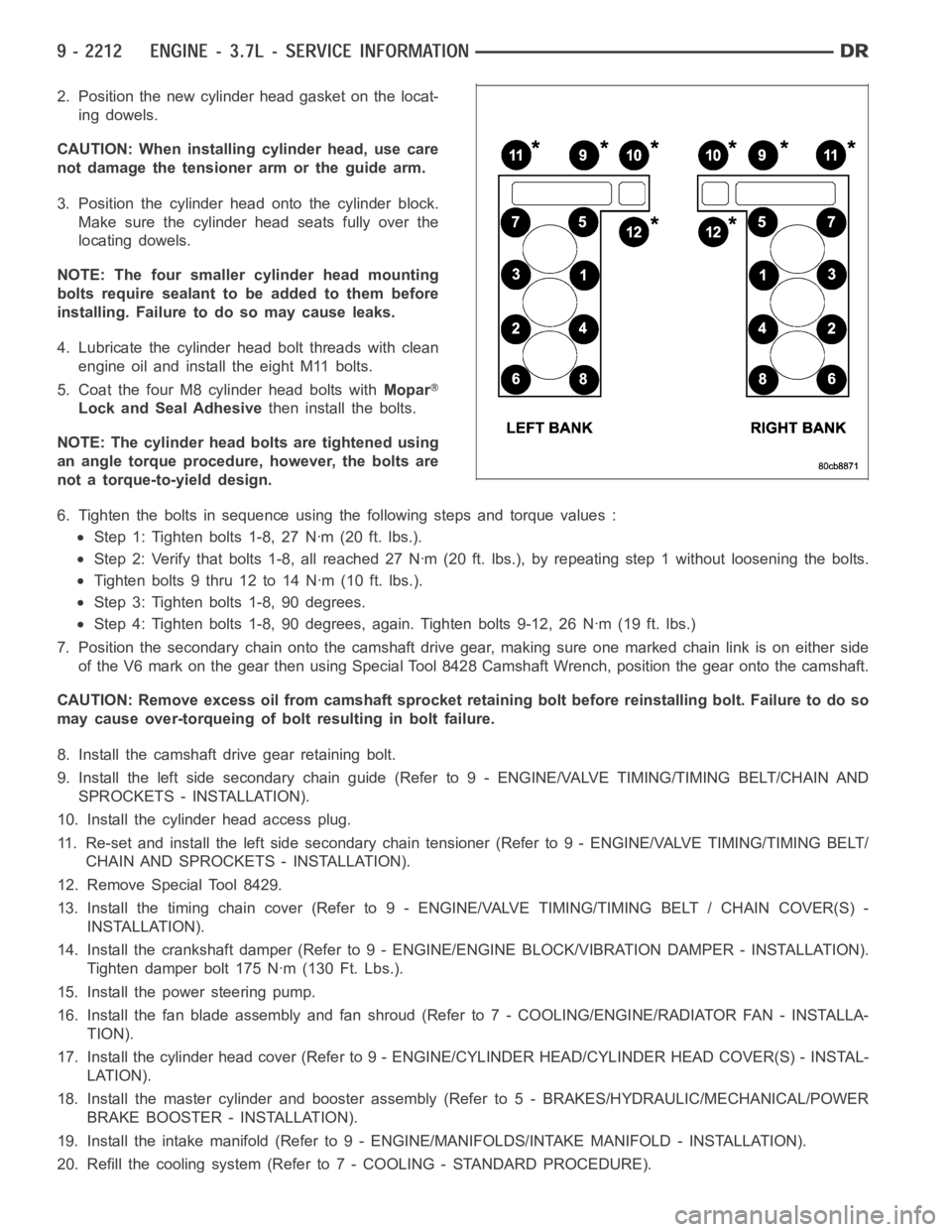
6. Tighten the bolts in sequence using the following steps and torque values:
Step 1: Tighten bolts 1-8, 27 Nꞏm (20 ft. lbs.).
Step 2: Verify that bolts 1-8, all reached 27 Nꞏm (20 ft. lbs.), by repeatingstep 1 without loosening the bolts.
Tightenbolts9thru12to14Nꞏm(10ft.lbs.).
Step 3: Tighten bolts 1-8, 90 degrees.
Step 4: Tighten bolts 1-8, 90 degrees, again. Tighten bolts 9-12, 26 Nꞏm (19ft. lbs.)
7. Position the secondary chain onto the camshaft drive gear, making sure one marked chain link is on either side
of the V6 mark on the gear then using Special Tool 8428 Camshaft Wrench, position the gear onto the camshaft.
CAUTION: Remove excess oil from camshaft sprocket retaining bolt before reinstalling bolt. Failure to do so
may cause over-torqueing of bolt resulting in bolt failure.
8. Install the camshaft drive gear retaining bolt.
9. Install the left side secondary chain guide (Refer to 9 - ENGINE/VALVE TIMING/TIMING BELT/CHAIN AND
SPROCKETS - INSTALLATION).
10. Install the cylinder head access plug.
11. Re-set and install the left side secondary chain tensioner (Refer to 9 -ENGINE/VALVE TIMING/TIMING BELT/
CHAIN AND SPROCKETS - INSTALLATION).
12. Remove Special Tool 8429.
13. Install the timing chain cover (Refer to 9 - ENGINE/VALVE TIMING/TIMING BELT / CHAIN COVER(S) -
INSTALLATION).
14. Install the crankshaft damper (Refer to 9 - ENGINE/ENGINE BLOCK/VIBRATION DAMPER - INSTALLATION).
Tighten damper bolt 175 Nꞏm (130 Ft. Lbs.).
15. Install the power steering pump.
16. Install the fan blade assembly and fan shroud (Refer to 7 - COOLING/ENGINE/RADIATOR FAN - INSTALLA-
TION).
17. Install the cylinder head cover (Refer to 9 - ENGINE/CYLINDER HEAD/CYLINDER HEAD COVER(S) - INSTAL-
LATION).
18. Install the master cylinder and booster assembly (Refer to 5 - BRAKES/HYDRAULIC/MECHANICAL/POWER
BRAKE BOOSTER - INSTALLATION).
19. Install the intake manifold (Refer to 9 - ENGINE/MANIFOLDS/INTAKE MANIFOLD - INSTALLATION).
20. Refill the cooling system (Refer to 7 - COOLING - STANDARD PROCEDURE).
Page 1528 of 5267
VALVES & SEATS - INTAKE/EXHAUST
DESCRIPTION
The valves are made of heat resistant steel and have chrome plated stems to prevent scuffing. Each valve is actu-
ated by a roller rocker arm which pivots on a stationary lash adjuster. All valves use three bead lock keepers to
retain the springs and promote valve rotation.
STANDARD PROCEDURE - REFACING
NOTE: Valve seats that are worn or burned can be
reworked, provided that correct angle and seat
width are maintained. Otherwise the cylinder head
must be replaced.
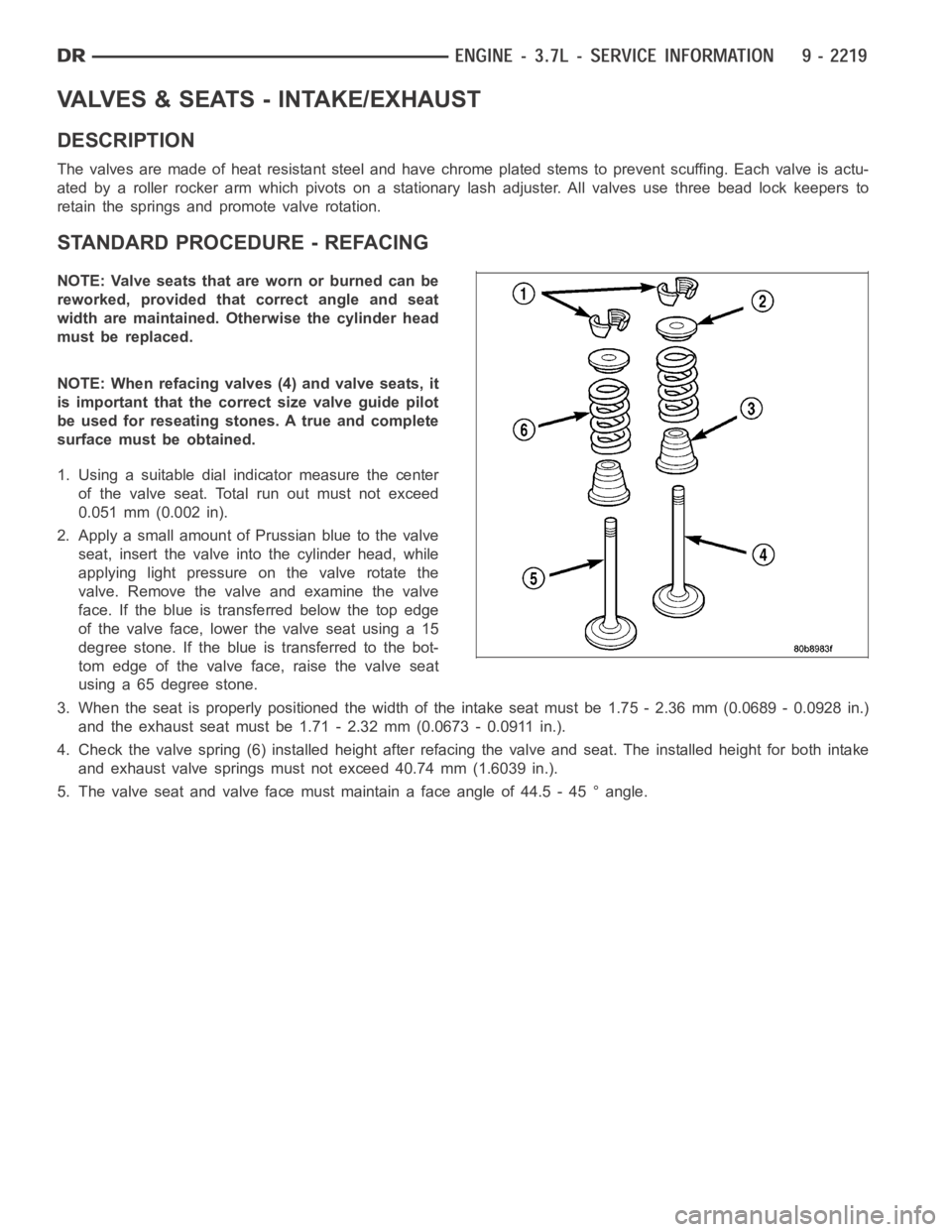
NOTE: When refacing valves (4) and valve seats, it
is important that the correct size valve guide pilot
be used for reseating stones. A true and complete
surface must be obtained.
1. Using a suitable dial indicator measure the center
of the valve seat. Total run out must not exceed
0.051 mm (0.002 in).
2. Apply a small amount of Prussian blue to the valve
seat, insert the valve into the cylinder head, while
applying light pressure on the valve rotate the
valve. Remove the valve and examine the valve
face. If the blue is transferred below the top edge
of the valve face, lower the valve seat using a 15
degree stone. If the blue is transferred to the bot-
tom edge of the valve face, raise the valve seat
using a 65 degree stone.
3. When the seat is properly positioned the width of the intake seat must be 1.75 - 2.36 mm (0.0689 - 0.0928 in.)
and the exhaust seat must be 1.71 - 2.32 mm (0.0673 - 0.0911 in.).
4. Check the valve spring (6) installed height after refacing the valve andseat. The installed height for both intake
and exhaust valve springs must not exceed 40.74 mm (1.6039 in.).
5. The valve seat and valve face must maintain a face angle of 44.5 - 45 ° angle.
Page 1659 of 5267
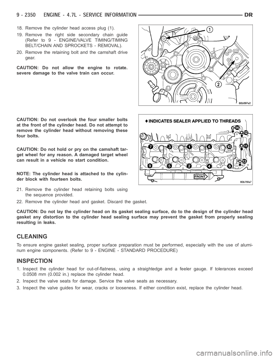
18. Remove the cylinder head access plug (1).
19. Remove the right side secondary chain guide
(Refer to 9 - ENGINE/VALVE TIMING/TIMING
BELT/CHAIN AND SPROCKETS - REMOVAL).
20. Remove the retaining bolt and the camshaft drive
gear.
CAUTION: Do not allow the engine to rotate.
severe damage to the valve train can occur.
CAUTION: Do not overlook the four smaller bolts
at the front of the cylinder head. Do not attempt to
remove the cylinder head without removing these
four bolts.
CAUTION: Do not hold or pry on the camshaft tar-
get wheel for any reason. A damaged target wheel
can result in a vehicle no start condition.
NOTE: The cylinder head is attached to the cylin-
der block with fourteen bolts.
21. Remove the cylinder head retaining bolts using
the sequence provided.
22. Remove the cylinder head and gasket. Discard the gasket.
CAUTION: Do not lay the cylinder head on its gasket sealing surface, do to the design of the cylinder head
gasket any distortion to the cylinder head sealing surface may prevent thegasket from properly sealing
resulting in leaks.
CLEANING
To ensure engine gasket sealing, proper surface preparation must be performed, especially with the use of alumi-
num engine components. (Refer to 9 - ENGINE - STANDARD PROCEDURE)
INSPECTION
1. Inspect the cylinder head for out-of-flatness, using a straightedge and a feeler gauge. If tolerances exceed
0.0508 mm (0.002 in.) replace the cylinder head.
2. Inspect the valve seats for damage. Service the valve seats as necessary.
3. Inspect the valve guides for wear, cracks or looseness. If either condition exist, replace the cylinder head.
Page 1680 of 5267
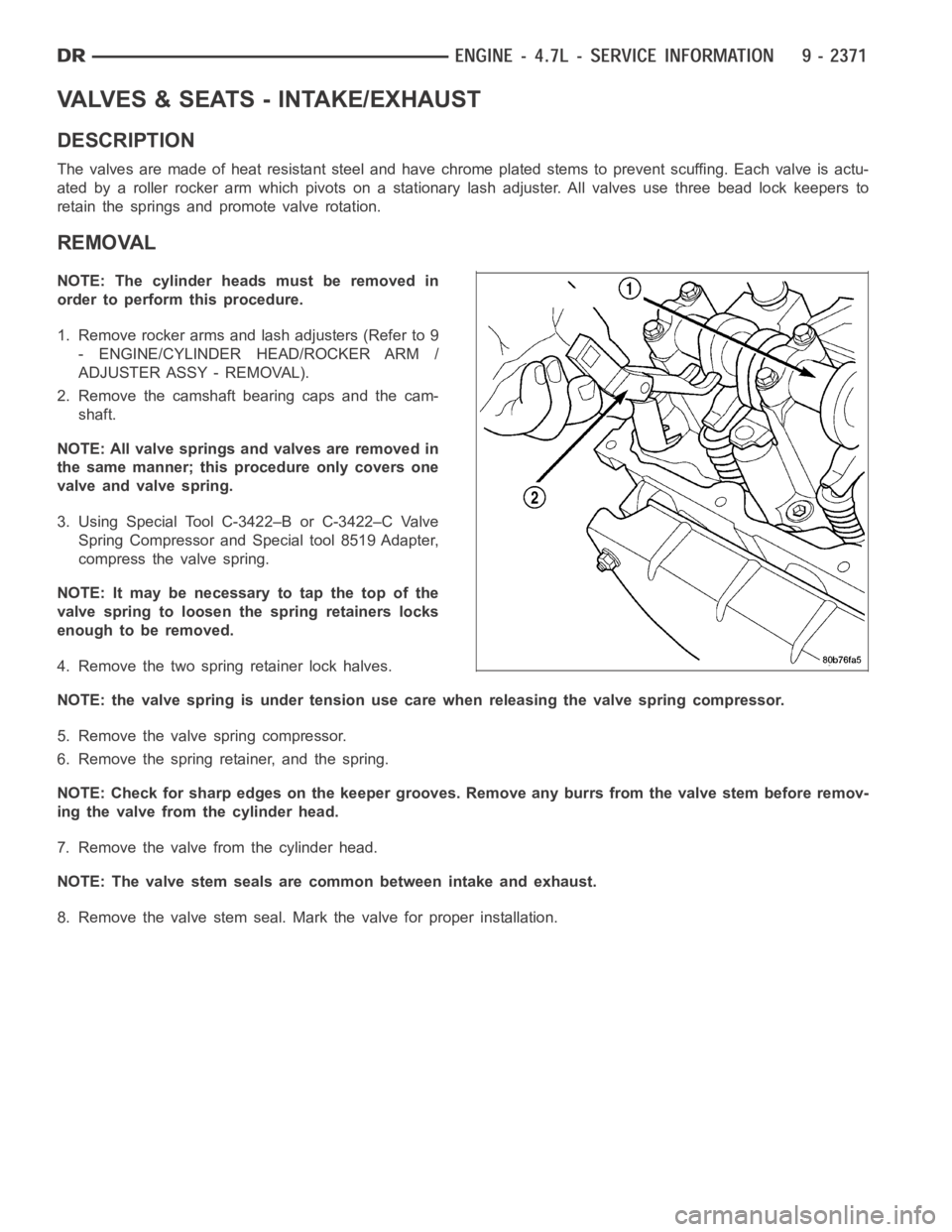
VALVES & SEATS - INTAKE/EXHAUST
DESCRIPTION
The valves are made of heat resistant steel and have chrome plated stems to prevent scuffing. Each valve is actu-
ated by a roller rocker arm which pivots on a stationary lash adjuster. All valves use three bead lock keepers to
retain the springs and promote valve rotation.
REMOVAL
NOTE: The cylinder heads must be removed in
order to perform this procedure.
1. Remove rocker arms and lash adjusters (Refer to 9
- ENGINE/CYLINDER HEAD/ROCKER ARM /
ADJUSTER ASSY - REMOVAL).
2. Remove the camshaft bearing caps and the cam-
shaft.
NOTE: All valve springs and valves are removed in
the same manner; this procedure only covers one
valve and valve spring.
3. Using Special Tool C-3422–B or C-3422–C Valve
Spring Compressor and Special tool 8519 Adapter,
compress the valve spring.
NOTE: It may be necessary to tap the top of the
valve spring to loosen the spring retainers locks
enough to be removed.
4. Remove the two spring retainer lock halves.
NOTE: the valve spring is under tension use care when releasing the valve spring compressor.
5. Remove the valve spring compressor.
6. Remove the spring retainer, and the spring.
NOTE: Check for sharp edges on the keeper grooves. Remove any burrs from thevalvestembeforeremov-
ing the valve from the cylinder head.
7. Remove the valve from the cylinder head.
NOTE: The valve stem seals are common between intake and exhaust.
8. Remove the valve stem seal. Mark the valve for proper installation.
Page 1793 of 5267
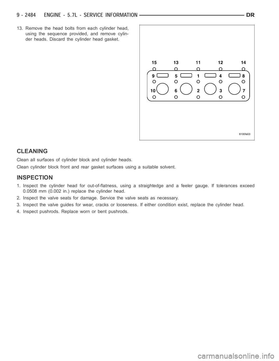
13. Remove the head bolts from each cylinder head,
using the sequence provided, and remove cylin-
der heads. Discard the cylinder head gasket.
CLEANING
Clean all surfaces of cylinder block and cylinder heads.
Clean cylinder block front and rear gasket surfaces using a suitable solvent.
INSPECTION
1. Inspect the cylinder head for out-of-flatness, using a straightedge and a feeler gauge. If tolerances exceed
0.0508 mm (0.002 in.) replace the cylinder head.
2. Inspect the valve seats for damage. Service the valve seats as necessary.
3. Inspect the valve guides for wear, cracks or looseness. If either condition exist, replace the cylinder head.
4. Inspect pushrods. Replace worn or bent pushrods.
Page 1805 of 5267
VALVES & SEATS - INTAKE/EXHAUST
DESCRIPTION
DESCRIPTION - VALVE GUIDES
The valve guides are made of powdered metal and are pressed into the cylinder head. The guides are not replace-
able or serviceable, and valve guide reaming is not recommended. If the guides are worn beyond acceptable limits,
replace the cylinder heads.
DESCRIPTION
Both the intake and exhaust valves are made of steel. The intake valve is 50.93 mm (2.00 inches) in diameter and
the exhaust valve is 39.53 mm (1.55 inches) in diameter. All valves use three bead lock keepers to retain the
springs and promote valve rotation.
STANDARD PROCEDURE - REFACING
NOTE: Valve seats that are worn or burned can be reworked, provided that correct angle and seat width are
maintained. Otherwise the cylinder head must be replaced.
NOTE: When refacing valves and valve seats, it is important that the correct size valve guide pilot be used
for reseating stones. A true and complete surface must be obtained.
1. Using a suitable dial indicator measure the center of the valve seat Total run out must not exceed 0.051 mm
(0.002 in).
2. Apply a small amount of Prussian blue to the valve seat, insert the valve into the cylinder head, while applying
light pressure on the valve rotate the valve. Remove the valve and examine the valve face. If the blue is trans-
ferred below the top edge of the valve face, lower the valve seat using a 15 degree stone. If the blue is trans-
ferred to the bottom edge of the valve face, raise the valve seat using a 65 degree stone.
3. When the seat is properly positioned the width of the intake seat must be 1.018 - 1.62 mm (0.0464 - 0.0637 in.)
and the exhaust seat must be 1.48 - 1.92 mm (0.058 - 0.075 in.).
4. Check the valve spring installed height after refacing the valve and seat.Theinstalledheightforbothintakeand
exhaust valve springs must not exceed 46.0 mm (1.81 in.).
VALVE FACE AND VALVE SEAT ANGLE CHART
DESCRIPTION SPECIFICATION
SEAT WIDTH
INTAKE 1.018 - 1.62 mm
(0.0464 - 0.0637 in.)
EXHAUST 1.48 - 1.92 mm
(0.058 - 0.075 in.)
FA C E A N G L E
(INT. AND EXT.) 45° - 45
1⁄2°
SEAT ANGLE
(INT. AND EXT.) 44
1⁄2° - 45°
Page 1806 of 5267
5. The valve seat must maintain an angle of 44.5 –
45.0 degrees angle.
6. Thevalvefacemustmaintainafaceangleof45.0
– 45.5 degrees angle.
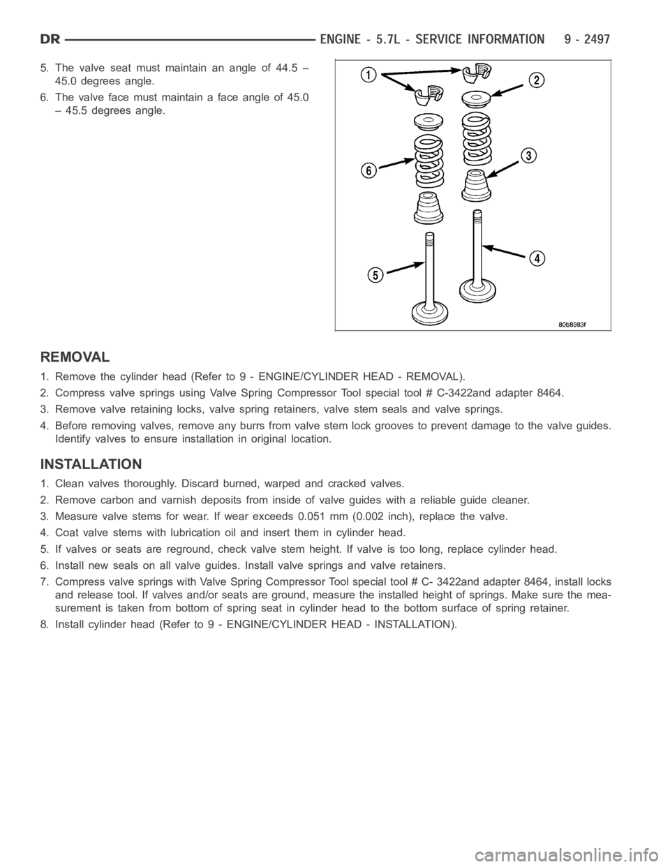
REMOVAL
1. Remove the cylinder head (Refer to 9 - ENGINE/CYLINDER HEAD - REMOVAL).
2. Compress valve springs using Valve Spring Compressor Tool special tool# C-3422and adapter 8464.
3. Remove valve retaining locks, valve spring retainers, valve stem sealsand valve springs.
4. Before removing valves, remove any burrs from valve stem lock grooves toprevent damage to the valve guides.
Identify valves to ensure installation in original location.
INSTALLATION
1. Clean valves thoroughly. Discard burned, warped and cracked valves.
2. Remove carbon and varnish deposits from inside of valve guides with a reliable guide cleaner.
3. Measure valve stems for wear. If wear exceeds 0.051 mm (0.002 inch), replace the valve.
4. Coat valve stems with lubrication oil and insert them in cylinder head.
5. If valves or seats are reground, check valve stem height. If valve is too long, replace cylinder head.
6. Install new seals on all valve guides. Install valve springs and valve retainers.
7. Compress valve springs with Valve Spring Compressor Tool special tool #C- 3422and adapter 8464, install locks
and release tool. If valves and/or seats are ground, measure the installedheight of springs. Make sure the mea-
surement is taken from bottom of spring seat in cylinder head to the bottom surface of spring retainer.
8. Install cylinder head (Refer to 9 - ENGINE/CYLINDER HEAD - INSTALLATION).