2006 DODGE RAM SRT-10 door lock
[x] Cancel search: door lockPage 2241 of 5267
OPERATION
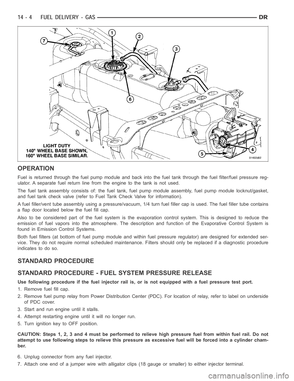
Fuel is returned through the fuel pump module and back into the fuel tank through the fuel filter/fuel pressure reg-
ulator. A separate fuel return line from the engine to the tank is not used.
The fuel tank assembly consists of: the fuel tank, fuel pump module assembly, fuel pump module locknut/gasket,
and fuel tank check valve (refer to Fuel Tank Check Valve for information).
A fuel filler/vent tube assembly using apressure/vacuum,1/4 turn fuel filler cap is used. The fuel filler tube contains
a flap door located below the fuel fill cap.
Also to be considered part of the fuelsystem is the evaporation control system. This is designed to reduce the
emission of fuel vapors into the atmosphere. The description and functionof the Evaporative Control System is
found in Emission Control Systems.
Both fuel filters (at bottom of fuel pump module and within fuel pressure regulator) are designed for extended ser-
vice. They do not require normal scheduled maintenance. Filters should only be replaced if a diagnostic procedure
indicates to do so.
STANDARD PROCEDURE
STANDARD PROCEDURE - FUEL SYSTEM PRESSURE RELEASE
Use following procedure if the fuel injector rail is, or is not equipped with a fuel pressure test port.
1. Remove fuel fill cap.
2. Remove fuel pump relay from Power Distribution Center (PDC). For location of relay, refer to label on underside
of PDC cover.
3. Start and run engine until it stalls.
4. Attempt restarting engine until it will no longer run.
5. Turn ignition key to OFF position.
CAUTION: Steps 1, 2, 3 and 4 must be performed to relieve high pressure fuel from within fuel rail. Do not
attempt to use following steps to relieve this pressure as excessive fuel will be forced into a cylinder cham-
ber.
6. Unplug connector from any fuel injector.
7. Attach one end of a jumper wire with alligator clips (18 gauge or smaller)to either injector terminal.
Page 2427 of 5267
KEY-IN IGNITION SWITCH
DESCRIPTION
The key-in ignition switch is integral to the ignition switch, which is mounted on the left side of the steering column.
ItclosesapathtogroundfortheCentralTimerModule(CTM)whentheignition key is inserted in the ignition key
cylinder and the driver door ajar switch is closed (driver door is open). The key-in ignition switch opens the ground
path when the key is removed from the ignition key cylinder. The ground pathis also opened when the driver door
ajar switch is open (driver door is closed).
The key-in ignition switch cannot be repaired and, if faulty or damaged, the entire ignition switch must be replaced,
(Refer to 19 - STEERING/COLUMN/IGNITION SWITCH - REMOVAL).
DIAGNOSIS AND TESTING
IGNITION SWITCH AND KEY LOCK CYLINDER
ELECTRICAL DIAGNOSIS
For ignition switch electrical schematics, refer to Ignition Switch in the appropriate section of Electrical Wiring Dia-
grams.
MECHANICAL DIAGNOSIS (KEY DIFFICULT TO ROTATE)
(Refer to 19 - STEERING/COLUMN/IGNITION SWITCH - DIAGNOSIS AND TESTING).
Page 4339 of 5267
BODY
WARNING
SAFETY PRECAUTIONS AND WARNINGS
WARNING: Use an OSHA approved breathing filter when spraying paint or solvents in a confined area. Per-
sonal injury can result.
Avoidprolongedskincontactwithpetroleumoralcohol–basedcleaningsolvents. Personal injury can
result.
Do not stand under a hoisted vehicle that is not properly supported on safety stands. Personal injury can
result.
CAUTION: When holes must be drilled or punched in an inner body panel, verify depth of space to the outer
body panel, electrical wiring, or other components. Damage to vehicle canresult.
Do not weld exterior panels unless combustible material on the interior ofvehicle is removed from the
repair area. Fire or hazardous conditions, can result.
Always have a fire extinguisher ready for use when welding.
Disconnect the negative (-) cable clamp from the battery when servicing electrical components that are
live when the ignition is OFF. Damage to electrical system can result.
Do not use abrasive chemicals or compounds on painted surfaces. Damage to finish can result.
Do not use harsh alkaline based cleaning solvents on painted or upholstered surfaces. Damage to finish
or color can result.
Do not hammer or pound on plastic trim panel when servicing interior trim. Plastic panels can break.
DIAGNOSIS AND TESTING
WAT E R L E A K S
Water leaks can be caused by poor sealing, improper body component alignment, body seam porosity, missing
plugs, or blocked drain holes. Centrifugal and gravitational force can cause water to drip from a location away from
the actual leak point, making leak detection difficult. All body sealing points should be water tight in normal wet-
driving conditions. Water flowing downward from the front of the vehicle should not enter the passenger or luggage
compartment. Moving sealing surfaces will not always seal water tight under all conditions. At times, side glass or
door seals will allow water to enter the passenger compartment during highpressure washing or hard driving rain
(severe) conditions. Overcompensating on door or glass adjustments to stop a water leak that occurs under severe
conditions can cause premature sealwear and excessive closing or latching effort. After completing a repair, water
test vehicle to verify leak has stopped before returning vehicle to use.
VISUAL INSPECTION BEFORE WATER LEAK TESTS
Verify that floor and body plugs are in place, body drains are clear, and body components are properly aligned and
sealed. If component alignment or sealing is necessary, refer to the appropriate section of this group for proper
procedures.
WATER LEAK TESTS
WARNING: Do not use electric shop lights or tools in water test area. Personal injury can result.
When the conditions causing a water leak have been determined, simulate the conditions as closely as possible.
Ifaleakoccurswiththevehicleparkedinasteadylightrain,floodtheleak area with an open-ended garden
hose.
If a leak occurs while driving at highway speeds in a steady rain, test the leak area with a reasonable velocity
stream or fan spray of water. Direct the spray in a direction comparable to actual conditions.
If a leak occurs when the vehicle is parked on an incline, hoist the end or sideofthevehicletosimulatethis
condition. This method can be used when the leak occurs when the vehicle accelerates, stops or turns. If the
leak occurs on acceleration, hoist the front of the vehicle. If the leak occurs when braking, hoist the back of the
Page 4341 of 5267
POSSIBLE CAUSE OF WIND NOISE
Moldings standing away from body surface can catch wind and whistle.
Gaps in sealed areas behind overhanging body flanges can cause wind-rushing sounds.
Misaligned movable components.
Missing or improperly installed plugs in pillars.
Weld burn through holes.
Improperly installed roof rack cross bars.
STANDARD PROCEDURE
BODY LUBRICATION
All mechanisms and linkages should be lubricated when necessary. This will maintain ease of operation and provide
protection against rust and excessive wear. The weatherstrip seals should be lubricated to prolong their life as well
as to improve door sealing.
All applicable exterior and interior vehicle operating mechanisms should be inspected and cleaned. Pivot/sliding con-
tact areas on the mechanisms should then be lubricated.
1. When necessary, lubricate the operating mechanisms with the specifiedlubricants.
2. Apply silicone lubricant to a clothand wipe it on door seals to avoid over-spray that can soil passenger’s cloth-
ing.
3. Before applying lubricant, the component should be wiped clean. After lubrication, any excess lubricant should be
removed.
4. The hood latch, latch release mechanism, latch striker, and safety latch should be lubricated periodically.
5. The door lock cylinders should be lubricated twice each year (preferably autumn and spring).
Spray a small amount of lock cylinder lubricant directly into the lock cylinder.
Apply a small amount to the key and insert it into the lock cylinder.
Rotate it to the locked position and then back to the unlocked position several times.
Remove the key. Wipe the lubricant from it with a clean cloth to avoid soiling of clothing.
HEAT STAKING
1. Remove trim panel.
2. Bend or move the trim panel components at the heat staked joints. Observethe heat staked locations and/or
component seams for looseness.
3. Heat stake the components.
a. If the heat staked or component seam location is loose, hold the two components tightly together and using
a soldering gun with a flat tip, melt the material securing the components together. Do not over heat the
affected area, damage to the exterior of the trim panel may occur.
b. Iftheheatstakedmaterialisbrokenormissing,useahotglueguntoapplynewmaterialtotheareatobe
repaired. The panels that are being heat staked must be held together whiletheapplyingtheglue.Oncethe
new material is in place, it may be necessary to use a soldering gun to melt the newly applied material. Do
not over heat the affected area, damage to the exterior of the trim panel mayoccur.
4. Allow the repaired area to cool and verify the repair.
5. Install trim panel.
BUZZ, SQUEAK & RATTLE
Buzz, Squeak & Rattles (BSR) may be caused by any one or more of the followingand may be corrected as indi-
cated:
Loose fasteners should be tightened to specifications.
Damaged or missing clips should be replaced.
Damaged trim panels should be replaced.
Incorrectly installed trim panels should be reinstalled properly.
Page 4342 of 5267
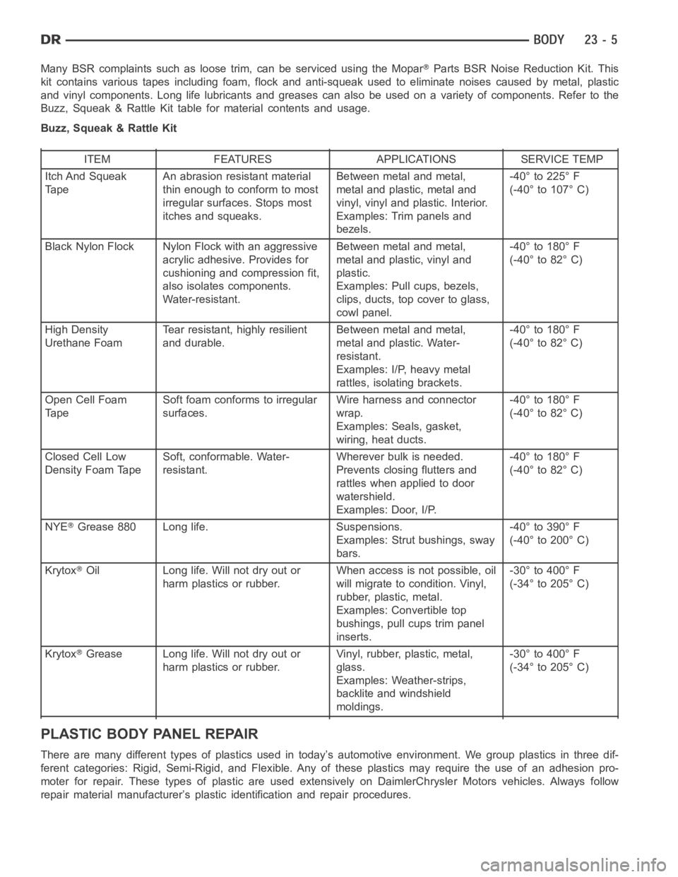
Many BSR complaints such as loose trim, can be serviced using the MoparParts BSR Noise Reduction Kit. This
kit contains various tapes including foam, flock and anti-squeak used to eliminate noises caused by metal, plastic
and vinyl components. Long life lubricants and greases can also be used on avariety of components. Refer to the
Buzz, Squeak & Rattle Kit table for material contents and usage.
Buzz, Squeak & Rattle Kit
ITEM FEATURES APPLICATIONS SERVICE TEMP
Itch And Squeak
TapeAn abrasion resistant material
thin enough to conform to most
irregular surfaces. Stops most
itches and squeaks.Between metal and metal,
metal and plastic, metal and
vinyl, vinyl and plastic. Interior.
Examples: Trim panels and
bezels.-40° to 225° F
(-40° to 107° C)
Black Nylon Flock Nylon Flock with an aggressive
acrylic adhesive. Provides for
cushioning and compression fit,
also isolates components.
Water-resistant.Between metal and metal,
metal and plastic, vinyl and
plastic.
Examples: Pull cups, bezels,
clips, ducts, top cover to glass,
cowl panel.-40° to 180° F
(-40° to 82° C)
High Density
Urethane FoamTear resistant, highly resilient
and durable.Between metal and metal,
metal and plastic. Water-
resistant.
Examples: I/P, heavy metal
rattles, isolating brackets.-40° to 180° F
(-40° to 82° C)
Open Cell Foam
TapeSoft foam conforms to irregular
surfaces.Wire harness and connector
wrap.
Examples: Seals, gasket,
wiring, heat ducts.-40° to 180° F
(-40° to 82° C)
Closed Cell Low
Density Foam TapeSoft, conformable. Water-
resistant.Wherever bulk is needed.
Prevents closing flutters and
rattles when applied to door
watershield.
Examples: Door, I/P.-40° to 180° F
(-40° to 82° C)
NYE
Grease 880 Long life. Suspensions.
Examples: Strut bushings, sway
bars.-40° to 390° F
(-40° to 200° C)
Krytox
Oil Long life. Will not dry out or
harm plastics or rubber.When access is not possible, oil
will migrate to condition. Vinyl,
rubber, plastic, metal.
Examples: Convertible top
bushings, pull cups trim panel
inserts.-30° to 400° F
(-34° to 205° C)
Krytox
Grease Long life. Will not dry out or
harm plastics or rubber.Vinyl, rubber, plastic, metal,
glass.
Examples: Weather-strips,
backlite and windshield
moldings.-30° to 400° F
(-34° to 205° C)
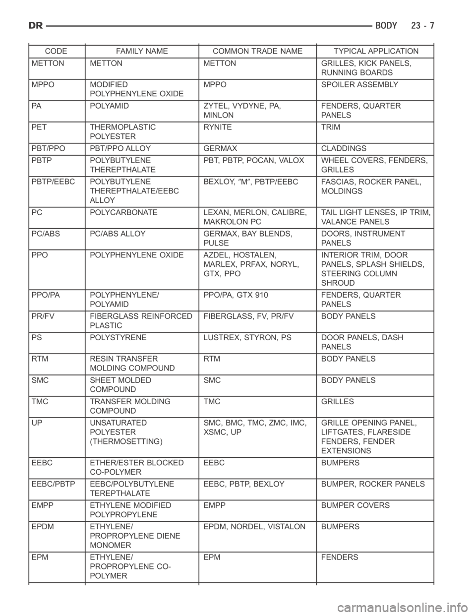
PLASTIC BODY PANEL REPAIR
There are many different types of plastics used in today’s automotive environment. We group plastics in three dif-
ferent categories: Rigid, Semi-Rigid, and Flexible. Any of these plastics may require the use of an adhesion pro-
moter for repair. These types of plastic are used extensively on DaimlerChrysler Motors vehicles. Always follow
repair material manufacturer’s plastic identification and repair procedures.
Page 4344 of 5267
CODE FAMILY NAME COMMON TRADE NAME TYPICAL APPLICATION
METTON METTON METTON GRILLES, KICK PANELS,
RUNNING BOARDS
MPPO MODIFIED
POLYPHENYLENE OXIDEMPPO SPOILER ASSEMBLY
PA POLYAMID ZYTEL, VYDYNE, PA,
MINLONFENDERS, QUARTER
PA N E L S
PET THERMOPLASTIC
POLYESTERRYNITE TRIM
PBT/PPO PBT/PPO ALLOY GERMAX CLADDINGS
PBTP POLYBUTYLENE
THEREPTHALATEPBT, PBTP, POCAN, VALOX WHEEL COVERS, FENDERS,
GRILLES
PBTP/EEBC POLYBUTYLENE
THEREPTHALATE/EEBC
ALLOYBEXLOY,
M, PBTP/EEBC FASCIAS, ROCKER PANEL,
MOLDINGS
PC POLYCARBONATE LEXAN, MERLON, CALIBRE,
MAKROLON PCTAIL LIGHT LENSES, IP TRIM,
VA L A N C E PA N E L S
PC/ABS PC/ABS ALLOY GERMAX, BAY BLENDS,
PULSEDOORS, INSTRUMENT
PA N E L S
PPO POLYPHENYLENE OXIDE AZDEL, HOSTALEN,
MARLEX, PRFAX, NORYL,
GTX, PPOINTERIOR TRIM, DOOR
PANELS, SPLASH SHIELDS,
STEERING COLUMN
SHROUD
PPO/PA POLYPHENYLENE/
POLYAMIDPPO/PA, GTX 910 FENDERS, QUARTER
PA N E L S
PR/FV FIBERGLASS REINFORCED
PLASTICFIBERGLASS, FV, PR/FV BODY PANELS
PS POLYSTYRENE LUSTREX, STYRON, PS DOOR PANELS, DASH
PA N E L S
RTM RESIN TRANSFER
MOLDING COMPOUNDRTM BODY PANELS
SMC SHEET MOLDED
COMPOUNDSMC BODY PANELS
TMC TRANSFER MOLDING
COMPOUNDTMC GRILLES
UP UNSATURATED
POLYESTER
(THERMOSETTING)SMC, BMC, TMC, ZMC, IMC,
XSMC, UPGRILLE OPENING PANEL,
LIFTGATES, FLARESIDE
FENDERS, FENDER
EXTENSIONS
EEBC ETHER/ESTER BLOCKED
CO-POLYMEREEBC BUMPERS
EEBC/PBTP EEBC/POLYBUTYLENE
TEREPTHALATEEEBC, PBTP, BEXLOY BUMPER, ROCKER PANELS
EMPP ETHYLENE MODIFIED
POLYPROPYLENEEMPP BUMPER COVERS
EPDM ETHYLENE/
PROPROPYLENE DIENE
MONOMEREPDM, NORDEL, VISTALON BUMPERS
EPM ETHYLENE/
PROPROPYLENE CO-
POLYMEREPM FENDERS
Page 4365 of 5267
page page
DOOR
REMOVAL .................................... 29
INSTALLATION ............................... 29
ADJUSTMENTS ............................... 29
DOOR GLASS
REMOVAL .................................... 34
INSTALLATION ............................... 35
EXTERIOR HANDLE
REMOVAL .................................... 36
INSTALLATION ............................... 36
GLASS RUN CHANNEL
REMOVAL
FRONT-ALL MODELS ....................... 37
REAR-QUAD CAB ........................... 37
REAR-STANDARD CAB ..................... 38
INSTALLATION
FRONT-ALL MODELS ....................... 38
REAR-QUAD CAB ........................... 39
REAR-STANDARD CAB ..................... 39
HINGE
REMOVAL .................................... 40
INSTALLATION ............................... 40
INTERIOR HANDLE ACTUATOR
REMOVAL .................................... 41
INSTALLATION ............................... 41
LATCH
REMOVAL .................................... 42INSTALLATION ............................... 43
ADJUSTMENTS ............................... 44
LATCH STRIKER
REMOVAL .................................... 45
INSTALLATION ............................... 45
ADJUSTMENTS ............................... 46
LOCK CYLINDER
REMOVAL .................................... 47
INSTALLATION ............................... 47
TRIM PANEL
REMOVAL .................................... 48
INSTALLATION ............................... 49
WATERDAM
REMOVAL .................................... 50
INSTALLATION ............................... 50
WINDOW REGULATOR - POWER
REMOVAL .................................... 51
INSTALLATION ............................... 52
WINDOW REGULATOR - MANUAL
REMOVAL .................................... 53
INSTALLATION ............................... 54
SIDE VIEW MIRROR FLAG
REMOVAL .................................... 55
INSTALLATION ............................... 55
Page 4384 of 5267
LOCK CYLINDER
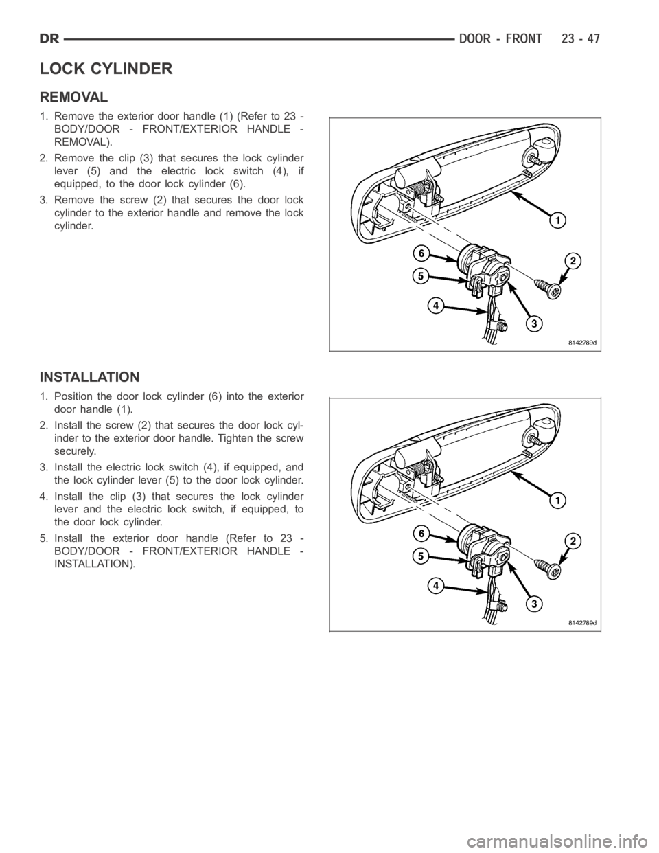
REMOVAL
1. Remove the exterior door handle (1) (Refer to 23 -
BODY/DOOR - FRONT/EXTERIOR HANDLE -
REMOVAL).
2. Remove the clip (3) that secures the lock cylinder
lever (5) and the electric lock switch (4), if
equipped, to the door lock cylinder (6).
3. Remove the screw (2) that secures the door lock
cylinder to the exterior handle and remove the lock
cylinder.
INSTALLATION
1. Position the door lock cylinder (6) into the exterior
door handle (1).
2. Install the screw (2) that secures the door lock cyl-
inder to the exterior door handle. Tighten the screw
securely.
3. Install the electric lock switch (4), if equipped, and
the lock cylinder lever (5) to the door lock cylinder.
4. Install the clip (3) that secures the lock cylinder
lever and the electric lock switch, if equipped, to
the door lock cylinder.
5. Install the exterior door handle (Refer to 23 -
BODY/DOOR - FRONT/EXTERIOR HANDLE -
INSTALLATION).