2006 DODGE RAM SRT-10 gas type
[x] Cancel search: gas typePage 3921 of 5267
d. Push overdrive piston into position in retainer.
e. Verify that the locating lugs entered the lug bores in the retainer.
6. Install intermediate shaft spacer on intermediate shaft.
7. Install overdrive piston thrust plate on overdrive piston.
8. Install overdrive piston thrust bearing on overdrive piston.
9. Install transmission speed sensorand o-ring seal in overdrive case.
INSTALLATION
1. Be sure overdrive unit Alignment Tool 6227-2 is
fully seated before moving unit. If tool is not seated
and gear splines rotate out of alignment, overdrive
unit will have to be disassembled in order to realign
splines.
2. If overdrive piston retainer was not removed during
service and original case gasket is no longer reus-
able, prepare new gasket by trimming it.
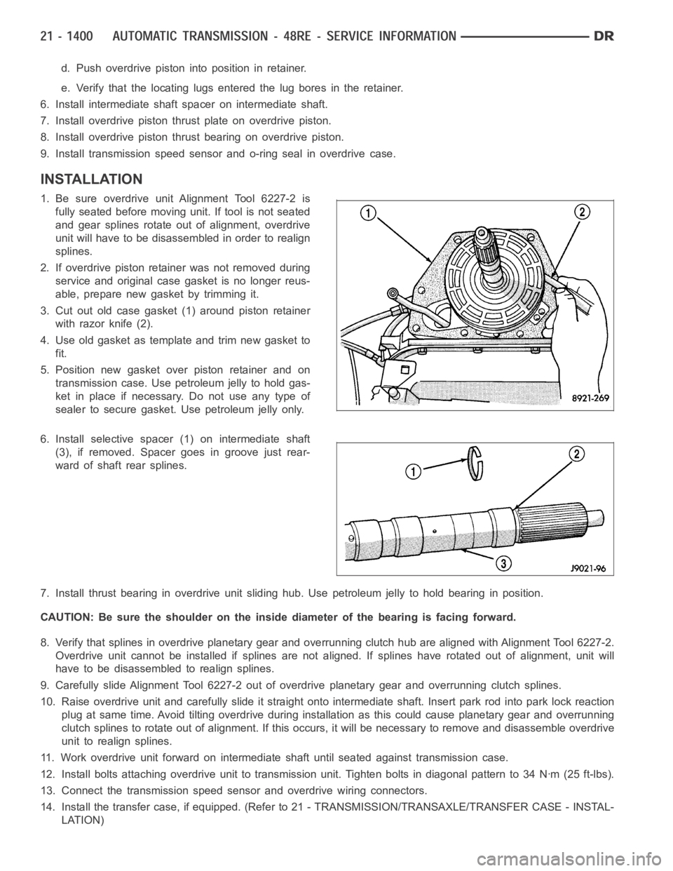
3. Cut out old case gasket (1) around piston retainer
with razor knife (2).
4. Use old gasket as template and trim new gasket to
fit.
5. Position new gasket over piston retainer and on
transmission case. Use petroleum jelly to hold gas-
ket in place if necessary. Do not use any type of
sealer to secure gasket. Use petroleum jelly only.
6. Install selective spacer (1) on intermediate shaft
(3), if removed. Spacer goes in groove just rear-
ward of shaft rear splines.
7. Install thrust bearing in overdrive unit sliding hub. Use petroleum jelly to hold bearing in position.
CAUTION: Be sure the shoulder on the inside diameter of the bearing is facingforward.
8. Verify that splines in overdrive planetary gear and overrunning clutchhub are aligned with Alignment Tool 6227-2.
Overdrive unit cannot be installed if splines are not aligned. If splines have rotated out of alignment, unit will
have to be disassembled to realign splines.
9. Carefully slide Alignment Tool 6227-2 out of overdrive planetary gear and overrunning clutch splines.
10. Raise overdrive unit and carefully slide it straight onto intermediate shaft. Insert park rod into park lock reaction
plug at same time. Avoid tilting overdrive during installation as this could cause planetary gear and overrunning
clutch splines to rotate out of alignment. If this occurs, it will be necessary to remove and disassemble overdrive
unit to realign splines.
11. Work overdrive unit forward on intermediate shaft until seated against transmission case.
12. Install bolts attaching overdrive unit to transmission unit. Tightenbolts in diagonal pattern to 34 Nꞏm (25 ft-lbs).
13. Connect the transmission speed sensor and overdrive wiring connectors.
14. Install the transfer case, if equipped. (Refer to 21 - TRANSMISSION/TRANSAXLE/TRANSFER CASE - INSTAL-
LATION)
Page 4006 of 5267

4. Remove timing valve cover.
5. Remove 3-4 timing valve and spring.
6. Remove 3-4 quick fill valve, spring and plug.
7. Remove 3-4 shift valve and spring.
8. Remove converter clutch valve, spring and plug.
9. Remove converter clutch timing valve, retainer and
valve spring.
CLEANING
Clean the valve housings, valves, plugs, springs, and separator plates with a standard parts cleaning solution only.
Do not use gasoline, kerosene, or any type of caustic solution.
Do not immerse any of the electrical components in cleaning solution. Clean the governor solenoid and sensor and
the dual solenoid and harness assembly by wiping them off with dry shop towels only.
Dry all except the electrical parts with compressed air. Make sure all passages are clean and free from obstructions.
Do not use rags or shop towels to dry or wipe off valve body components. Lint from these materials can
stick to valve body parts, interfere with valve operation, and clog filters and fluid passages.
Wipe the governor pressure sensor and solenoid valve with dry, lint free shop towels only. The O-rings on the sen-
sor and solenoid valve are the only serviceable components. Be sure the vent ports in the solenoid valve are open
and not blocked by dirt or debris. Replace the valve and/or sensor only whenDRB scan tool diagnosis indicates this
is necessary. Or, if either part has sustained physical damage (dented, deformed, broken, etc.).
CAUTION: Do not turn the small screw at the end of the solenoid valve for any reason. Turning the screw
in either direction will ruin solenoid calibration and result in solenoidfailure. In addition, the filter on the
solenoid valve is NOT serviceable. Do not try to remove the filter as this will damage the valve housing.
INSPECTION
Inspect the throttle and manual valve levers and shafts. Do not attempt to straighten a bent shaft or correct a loose
lever. Replace these components if worn, bent, loose or damaged in any way.
Inspect all of the valve body mating surfaces for scratches, nicks, burrs,or distortion. Use a straightedge to check
surface flatness. Minor scratches may be removed with crocus cloth using only very light pressure.
Minor distortion of a valve body mating surface may be corrected by smoothing the surface with a sheet of crocus
cloth. Position the crocus cloth on a surface plate, sheet of plate glass orequally flat surface. If distortion is severe
or any surfaces are heavily scored, the valve body will have to be replaced.
CAUTION: Many of the valves and plugs, such as the throttle valve, shuttle valve plug, 1-2 shift valve and
1-2 governor plug, are made of coated aluminum. Aluminum components are identified by the dark color of
thespecialcoatingappliedtothesurface(orbytestingwithamagnet).Donot sand aluminum valves or
plugs under any circumstances. This practice could damage the special coating causing the valves/plugs to
stick and bind.
Inspect the valves and plugs for scratches, burrs, nicks, or scores. Minorsurface scratches on steel valves and
plugs can be removed with crocus cloth butdo not round off the edges of the valve or plug lands.Maintaining
Page 4017 of 5267
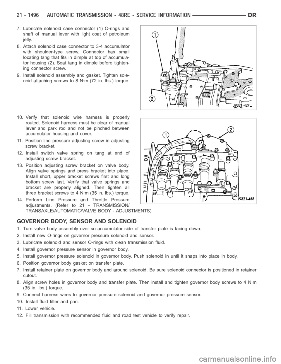
7. Lubricate solenoid case connector (1) O-rings and
shaft of manual lever with light coat of petroleum
jelly.
8. Attach solenoid case connector to 3-4 accumulator
with shoulder-type screw. Connector has small
locating tang that fits indimple at top of accumula-
tor housing (2). Seat tang in dimple before tighten-
ing connector screw.
9. Install solenoid assembly and gasket. Tighten sole-
noid attaching screws to 8 Nꞏm (72 in. lbs.) torque.
10. Verify that solenoid wire harness is properly
routed. Solenoid harness must be clear of manual
lever and park rod and not be pinched between
accumulator housing and cover.
11. Position line pressure adjusting screw in adjusting
screw bracket.
12. Install switch valve spring on tang at end of
adjusting screw bracket.
13. Position adjusting screw bracket on valve body.
Align valve springs and press bracket into place.
Install short, upper bracket screws first and long
bottom screw last. Verify that valve springs and
bracket are properly aligned. Then tighten all
three bracket screws to 4 Nꞏm (35 in. lbs.) torque.
14. Perform Line Pressure and Throttle Pressure
adjustments. (Refer to 21 - TRANSMISSION/
TRANSAXLE/AUTOMATIC/VALVE BODY - ADJUSTMENTS)
GOVERNOR BODY, SENSOR AND SOLENOID
1. Turn valve body assembly over so accumulator side of transfer plate is facing down.
2. Install new O-rings on governor pressure solenoid and sensor.
3. Lubricate solenoid and sensor O-rings with clean transmission fluid.
4. Install governor pressure sensor in governor body.
5. Install governor pressure solenoid in governor body. Push solenoid in until it snaps into place in body.
6. Position governor body gasket on transfer plate.
7. Install retainer plate on governor body and around solenoid. Be sure solenoid connector is positioned in retainer
cutout.
8. Align screw holes in governor body and transfer plate. Then install and tighten governor body screws to 4 Nꞏm
(35 in. lbs.) torque.
9. Connect harness wires to governor pressure solenoid and governor pressure sensor.
10. Install fluid filter and pan.
11. Lower vehicle.
12. Fill transmission with recommended fluid and road test vehicle to verify repair.
Page 4340 of 5267
vehicle. If the leak occurs on left turns, hoist the left side of the vehicle. If the leak occurs on right turns, hoist
the right side of the vehicle. For hoisting recommendations (Refer to LUBRICATION & MAINTENANCE/HOIST-
ING - STANDARD PROCEDURE).
WATER LEAK DETECTION
To detect a water leak point-of-entry, do a water test and watch for water tracks or droplets forming on the inside of
the vehicle. If necessary, remove interior trim covers or panels to gain visual access to the leak area. If the hose
cannot be positioned without being held, have someone help do the water test.
Some water leaks must be tested for a considerable length of time to become apparent. When a leak appears, find
the highest point of the water track or drop. The highest point usually willshow the point of entry. After leak point
has been found, repair the leak and water test to verify that the leak has stopped.
Locating the entry point of water that is leaking into a cavity between panels can be difficult. The trapped water may
splash or run from the cavity, often at adistance from the entry point. Mostwater leaks of this type become appar-
ent after accelerating, stopping, turning, or when on an incline.
MIRROR INSPECTION METHOD
When a leak point area is visually obstructed, use a suitable mirror to gainvisual access. A mirror can also be used
to deflect light to a limited-access area to assist in locating a leak point.
BRIGHT LIGHT LEAK TEST METHOD
Some water leaks in the luggage compartment can be detected without water testing. Position the vehicle in a
brightly lit area. From inside the darkened luggage compartment inspect around seals and body seams. If neces-
sary, have a helper direct a drop light over the suspected leak areas aroundthe luggage compartment. If light is
visible through a normally sealed location, water could enter through theopening.
PRESSURIZED LEAK TEST METHOD
When a water leak into the passenger compartment cannot be detected by water testing, pressurize the passenger
compartment and soap test exterior ofthe vehicle. To pressurize the passenger compartment, close all doors and
windows, start engine, and set heater control to high blower in HEAT position. If engine can not be started, connect
a charger to the battery to ensure adequate voltage to the blower. With interior pressurized, apply dish detergent
solution to suspected leak area on the exterior of the vehicle. Apply detergent solution with spray device or soft
bristle brush. If soap bubbles occur at a body seam, joint, seal or gasket, the leak entry point could be at that
location.
WIND NOISE
Wind noise is the result of most air leaks. Air leaks can be caused by poor sealing, improper body component
alignment, body seam porosity, or missing plugs in the engine compartmentor door hinge pillar areas. All body
sealing points should be airtight in normal driving conditions. Moving sealing surfaces will not always seal airtight
under all conditions. At times, side glass or door seals will allow wind noise to be noticed in the passenger com-
partment during high cross winds. Over compensating on door or glass adjustments to stop wind noise that occurs
under severe conditions can cause premature seal wear and excessive closing or latching effort. After a repair pro-
cedure has been performed, test vehicle to verify noise has stopped beforereturning vehicle to use.
VISUAL INSPECTION BEFORE TESTS
Verify that floor and body plugs are in place and body components are aligned and sealed. If component alignment
or sealing is necessary, refer to the appropriate section of this group forproper procedures.
ROAD TESTING WIND NOISE
1. Drive the vehicle to verify the general location of the wind noise.
2. Apply 50 mm (2 in.) masking tape in 150 mm (6 in.) lengths along weatherstrips, weld seams or moldings. After
each length is applied, drive the vehicle. If noise goes away after a piece of tape is applied, remove tape, locate,
and repair defect.
Page 4342 of 5267
Many BSR complaints such as loose trim, can be serviced using the MoparParts BSR Noise Reduction Kit. This
kit contains various tapes including foam, flock and anti-squeak used to eliminate noises caused by metal, plastic
and vinyl components. Long life lubricants and greases can also be used on avariety of components. Refer to the
Buzz, Squeak & Rattle Kit table for material contents and usage.
Buzz, Squeak & Rattle Kit
ITEM FEATURES APPLICATIONS SERVICE TEMP
Itch And Squeak
TapeAn abrasion resistant material
thin enough to conform to most
irregular surfaces. Stops most
itches and squeaks.Between metal and metal,
metal and plastic, metal and
vinyl, vinyl and plastic. Interior.
Examples: Trim panels and
bezels.-40° to 225° F
(-40° to 107° C)
Black Nylon Flock Nylon Flock with an aggressive
acrylic adhesive. Provides for
cushioning and compression fit,
also isolates components.
Water-resistant.Between metal and metal,
metal and plastic, vinyl and
plastic.
Examples: Pull cups, bezels,
clips, ducts, top cover to glass,
cowl panel.-40° to 180° F
(-40° to 82° C)
High Density
Urethane FoamTear resistant, highly resilient
and durable.Between metal and metal,
metal and plastic. Water-
resistant.
Examples: I/P, heavy metal
rattles, isolating brackets.-40° to 180° F
(-40° to 82° C)
Open Cell Foam
TapeSoft foam conforms to irregular
surfaces.Wire harness and connector
wrap.
Examples: Seals, gasket,
wiring, heat ducts.-40° to 180° F
(-40° to 82° C)
Closed Cell Low
Density Foam TapeSoft, conformable. Water-
resistant.Wherever bulk is needed.
Prevents closing flutters and
rattles when applied to door
watershield.
Examples: Door, I/P.-40° to 180° F
(-40° to 82° C)
NYE
Grease 880 Long life. Suspensions.
Examples: Strut bushings, sway
bars.-40° to 390° F
(-40° to 200° C)
Krytox
Oil Long life. Will not dry out or
harm plastics or rubber.When access is not possible, oil
will migrate to condition. Vinyl,
rubber, plastic, metal.
Examples: Convertible top
bushings, pull cups trim panel
inserts.-30° to 400° F
(-34° to 205° C)
Krytox
Grease Long life. Will not dry out or
harm plastics or rubber.Vinyl, rubber, plastic, metal,
glass.
Examples: Weather-strips,
backlite and windshield
moldings.-30° to 400° F
(-34° to 205° C)
PLASTIC BODY PANEL REPAIR
There are many different types of plastics used in today’s automotive environment. We group plastics in three dif-
ferent categories: Rigid, Semi-Rigid, and Flexible. Any of these plastics may require the use of an adhesion pro-
moter for repair. These types of plastic are used extensively on DaimlerChrysler Motors vehicles. Always follow
repair material manufacturer’s plastic identification and repair procedures.
Page 5093 of 5267
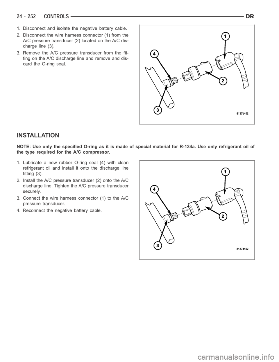
1. Disconnect and isolate the negative battery cable.
2. Disconnect the wire harness connector (1) from the
A/C pressure transducer (2) located on the A/C dis-
charge line (3).
3. Remove the A/C pressure transducer from the fit-
ting on the A/C discharge line and remove and dis-
card the O-ring seal.
INSTALLATION
NOTE:UseonlythespecifiedO-ringasitismadeofspecialmaterialforR-134a. Use only refrigerant oil of
the type required for the A/C compressor.
1. Lubricate a new rubber O-ring seal (4) with clean
refrigerant oil and install it onto the discharge line
fitting (3).
2. Install the A/C pressure transducer (2) onto the A/C
discharge line. Tighten the A/C pressure transducer
securely.
3. Connect the wire harness connector (1) to the A/C
pressure transducer.
4. Reconnect the negative battery cable.
Page 5127 of 5267
PLUMBING
DESCRIPTION
The A/C refrigerant lines and hoses are used to carry the refrigerant between the various A/C system components.
The refrigerant lines and hoses for the R-134a system on this vehicle consist of a barrier-hose design with a nylon
tube sandwiched between rubber layers. The nylon tube helps to contain theR-134a refrigerant, which has a
smaller molecular structure than R-12 refrigerant. The ends of the refrigerant lines are made from lightweight alu-
minum or steel, and commonly use braze-less fittings.
Any kinks or sharp bends in the refrigerant lines and hoses will reduce the capacity of the entire A/C system and
can reduce the flow of refrigerant in the system. The radius of all bends in the flexible hose refrigerant lines should
be at least ten times the diameter of the hose and the refrigerant lines should be routed so they are at least 80
millimeters (3 inches) away from the exhaust manifold(s) and exhaust pipe(s).
OPERATION
High pressures are produced in the refrigerant system when the A/C compressor is operating. Extreme care must
be exercised to make sure that each of the refrigerant system connections is pressure-tight and leak free. It is a
good practice to inspect all flexible hose refrigerant lines at least oncea year to make sure they are in good con-
dition and properly routed.
The refrigerant lines and hoses are coupled to other A/C system componentswith block-type fittings. An O-ring seal,
or a flat steel gasket with an integral O-ring (dual plane seal), is used to mate the refrigerant line fittings with A/C
system components to ensure the integrity of the refrigerant system.
The refrigerant lines and hoses cannot be repaired and, if faulty or damaged, they must be replaced.
WARNING
WARNING: The A/C system contains refrigerant under high pressure. Repairs should only be performed by
qualified service personnel. Severe personal injury or death may result from improper service procedures.
WARNING: Avoid breathing the refrigerant and refrigerant oil vapor or mist. Exposure may irritate the eyes,
nose, and/or throat. Wear eye protection when servicing the A/C refrigerant system. Serious eye injury can
result from direct contact with the refrigerant. If eye contact occurs, seek medical attention immediately.
WARNING: Do not expose the refrigerant to open flame. Poisonous gas is createdwhenrefrigerantis
burned. An electronic leak detector is recommended. Severe personal injury or death may result from
improper service procedures.
WARNING: If accidental system discharge occurs, ventilate the work area before resuming service. Large
amounts of refrigerant released in a closed work area will displace the oxygen and cause suffocation and
death.
WARNING: The evaporation rate of R-134a refrigerant at average temperature and altitude is extremely high.
As a result, anything that comes in contact with the refrigerant will freeze. Always protect the skin or del-
icate objects from direct contact with the refrigerant.
WARNING: The R-134a service equipment or the vehicle refrigerant system should not be pressure tested or
leak tested with compressed air. Some mixtures of air and R-134a have been shown to be combustible at
elevated pressures. These mixtures are potentially dangerous, and may result in fire or explosion causing
property damage, personal injury or death.
Page 5149 of 5267
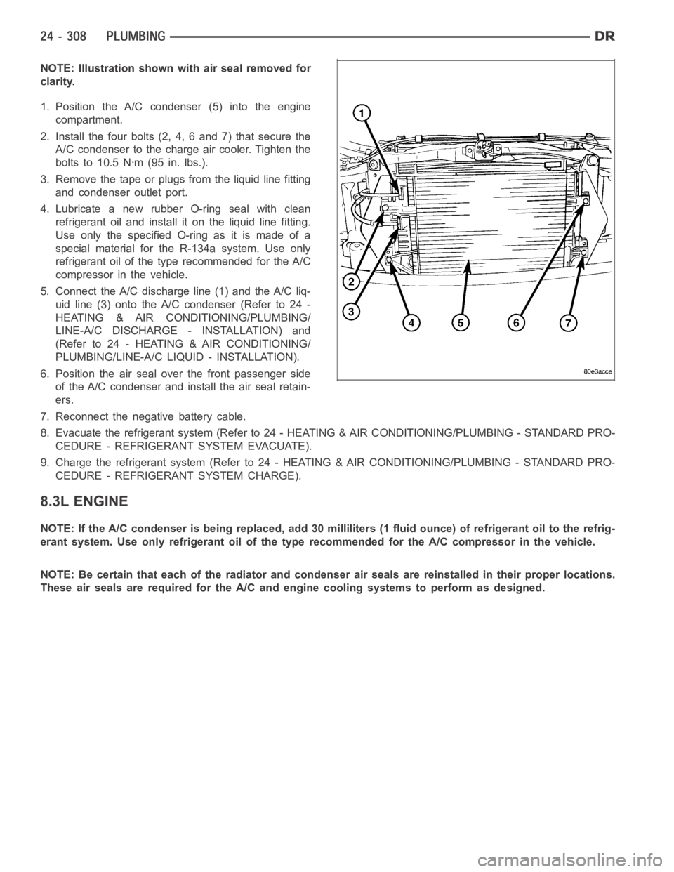
NOTE: Illustration shown with air seal removed for
clarity.
1. Position the A/C condenser (5) into the engine
compartment.
2. Install the four bolts (2, 4, 6 and 7) that secure the
A/C condenser to the charge air cooler. Tighten the
bolts to 10.5 Nꞏm (95 in. lbs.).
3. Remove the tape or plugs from the liquid line fitting
and condenser outlet port.
4. Lubricate a new rubber O-ring seal with clean
refrigerant oil and install it on the liquid line fitting.
UseonlythespecifiedO-ringasitismadeofa
special material for the R-134a system. Use only
refrigerant oil of the type recommended for the A/C
compressor in the vehicle.
5. Connect the A/C discharge line (1) and the A/C liq-
uid line (3) onto the A/C condenser (Refer to 24 -
HEATING & AIR CONDITIONING/PLUMBING/
LINE-A/C DISCHARGE - INSTALLATION) and
(Refer to 24 - HEATING & AIR CONDITIONING/
PLUMBING/LINE-A/C LIQUID - INSTALLATION).
6. Position the air seal over the front passenger side
of the A/C condenser and install the air seal retain-
ers.
7. Reconnect the negative battery cable.
8. Evacuate the refrigerant system (Refer to 24 - HEATING & AIR CONDITIONING/PLUMBING - STANDARD PRO-
CEDURE - REFRIGERANT SYSTEM EVACUATE).
9. Charge the refrigerant system (Refer to 24 - HEATING & AIR CONDITIONING/PLUMBING - STANDARD PRO-
CEDURE - REFRIGERANT SYSTEM CHARGE).
8.3L ENGINE
NOTE: If the A/C condenser is being replaced, add 30 milliliters (1 fluid ounce) of refrigerant oil to the refrig-
erant system. Use only refrigerant oil of the type recommended for the A/C compressor in the vehicle.
NOTE: Be certain that each of the radiator and condenser air seals are reinstalled in their proper locations.
These air seals are required for the A/C and engine cooling systems to perform as designed.