2006 DODGE RAM SRT-10 gas type
[x] Cancel search: gas typePage 2031 of 5267
STANDARD PROCEDURE
ENGINE CORE AND OIL GALLERY PLUGS
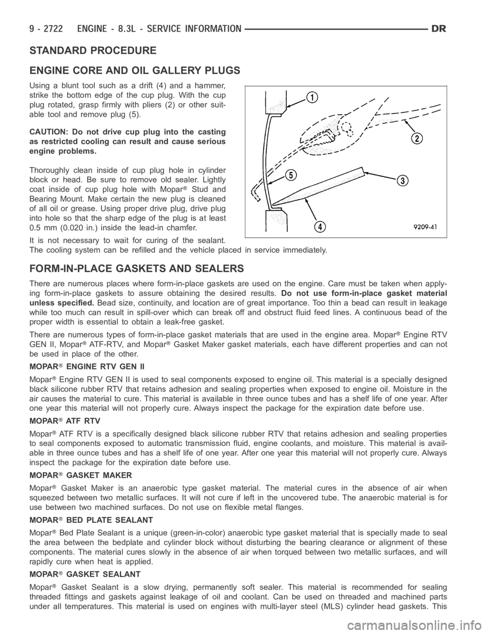
Using a blunt tool such as a drift (4) and a hammer,
strike the bottom edge of the cup plug. With the cup
plug rotated, grasp firmly with pliers (2) or other suit-
able tool and remove plug (5).
CAUTION: Do not drive cup plug into the casting
as restricted cooling can result and cause serious
engine problems.
Thoroughly clean inside of cup plug hole in cylinder
block or head. Be sure to remove old sealer. Lightly
coat inside of cup plug hole with Mopar
Stud and
Bearing Mount. Make certain the new plug is cleaned
of all oil or grease. Using proper drive plug, drive plug
into hole so that the sharp edge of the plug is at least
0.5 mm (0.020 in.) inside the lead-in chamfer.
It is not necessary to wait for curing of the sealant.
The cooling system can be refilled and the vehicle placed in service immediately.
FORM-IN-PLACE GASKETS AND SEALERS
There are numerous places where form-in-place gaskets are used on the engine. Care must be taken when apply-
ing form-in-place gaskets to assure obtaining the desired results.Do not use form-in-place gasket material
unless specified.Bead size, continuity, and location are of great importance. Too thin a bead can result in leakage
while too much can result in spill-overwhich can break off and obstruct fluid feed lines. A continuous bead of the
proper width is essential to obtain a leak-free gasket.
There are numerous types of form-in-place gasket materials that are used in the engine area. Mopar
Engine RTV
GEN II, Mopar
ATF-RTV, and MoparGasket Maker gasket materials, each have different properties and can not
be used in place of the other.
MOPAR
ENGINE RTV GEN II
Mopar
Engine RTV GEN II is used to seal components exposed to engine oil. This material is a specially designed
black silicone rubber RTV that retains adhesion and sealing properties when exposed to engine oil. Moisture in the
air causes the material to cure. This material is available in three ounce tubes and has a shelf life of one year. After
one year this material will not properly cure. Always inspect the package for the expiration date before use.
MOPAR
AT F R T V
Mopar
ATF RTV is a specifically designed black silicone rubber RTV that retains adhesion and sealing properties
to seal components exposed to automatic transmission fluid, engine coolants, and moisture. This material is avail-
able in three ounce tubes and has a shelf life of one year. After one year thismaterial will not properly cure. Always
inspect the package for the expiration date before use.
MOPAR
GASKET MAKER
Mopar
Gasket Maker is an anaerobic type gasket material. The material cures in the absence of air when
squeezed between two metallic surfaces. It will not cure if left in the uncovered tube. The anaerobic material is for
use between two machined surfaces. Do not use on flexible metal flanges.
MOPAR
BED PLATE SEALANT
Mopar
Bed Plate Sealant is a unique (green-in-color) anaerobic type gasket material that is specially made to seal
the area between the bedplate and cylinder block without disturbing the bearing clearance or alignment of these
components. The material cures slowly in the absence of air when torqued between two metallic surfaces, and will
rapidly cure when heat is applied.
MOPAR
GASKET SEALANT
Mopar
Gasket Sealant is a slow drying, permanently soft sealer. This material isrecommended for sealing
threaded fittings and gaskets against leakage of oil and coolant. Can be used on threaded and machined parts
under all temperatures. This material is used on engines with multi-layersteel (MLS) cylinder head gaskets. This
Page 2068 of 5267
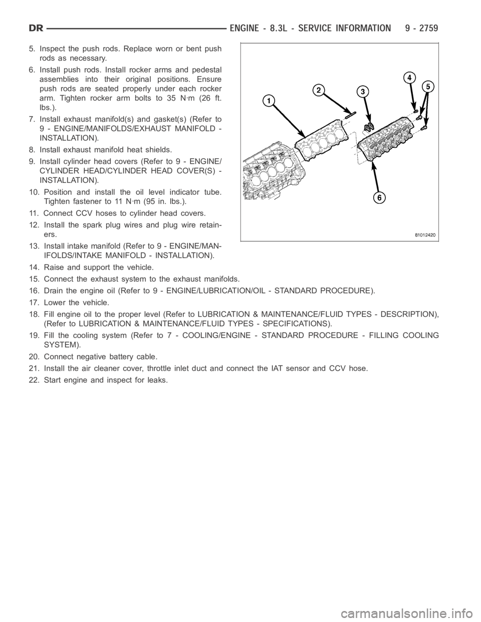
5. Inspect the push rods. Replace worn or bent push
rods as necessary.
6. Install push rods. Install rocker arms and pedestal
assemblies into their original positions. Ensure
push rods are seated properly under each rocker
arm.Tightenrockerarmboltsto35Nꞏm(26ft.
lbs.).
7. Install exhaust manifold(s) and gasket(s) (Refer to
9 - ENGINE/MANIFOLDS/EXHAUST MANIFOLD -
INSTALLATION).
8. Install exhaust manifold heat shields.
9. Install cylinder head covers (Refer to 9 - ENGINE/
CYLINDER HEAD/CYLINDER HEAD COVER(S) -
INSTALLATION).
10. Position and install the oil level indicator tube.
Tighten fastener to 11 Nꞏm (95 in. lbs.).
11. Connect CCV hoses to cylinder head covers.
12. Install the spark plug wires and plug wire retain-
ers.
13. Install intake manifold (Refer to 9 - ENGINE/MAN-
IFOLDS/INTAKE MANIFOLD - INSTALLATION).
14. Raise and support the vehicle.
15. Connect the exhaust systemto the exhaust manifolds.
16. Drain the engine oil (Refer to 9 - ENGINE/LUBRICATION/OIL - STANDARD PROCEDURE).
17. Lower the vehicle.
18. Fill engine oil to the proper level (Refer to LUBRICATION & MAINTENANCE/FLUID TYPES - DESCRIPTION),
(Refer to LUBRICATION & MAINTENANCE/FLUID TYPES - SPECIFICATIONS).
19. Fill the cooling system (Refer to 7 - COOLING/ENGINE - STANDARD PROCEDURE - FILLING COOLING
SYSTEM).
20. Connect negative battery cable.
21. Install the air cleaner cover, throttle inlet duct and connect the IAT sensor and CCV hose.
22. Start engine and inspect for leaks.
Page 2088 of 5267
OIL
STANDARD PROCEDURE
CHECKING ENGINE OIL LEVEL
The best time to check engine oil level is after the
vehicle has sat overnight. If the engine has been run-
ning, allow the engine to be shut off for at least 5 min-
utes before checking oil level.
Checking the oil while the vehicle is on level ground
will improve the accuracy of the oil level reading.
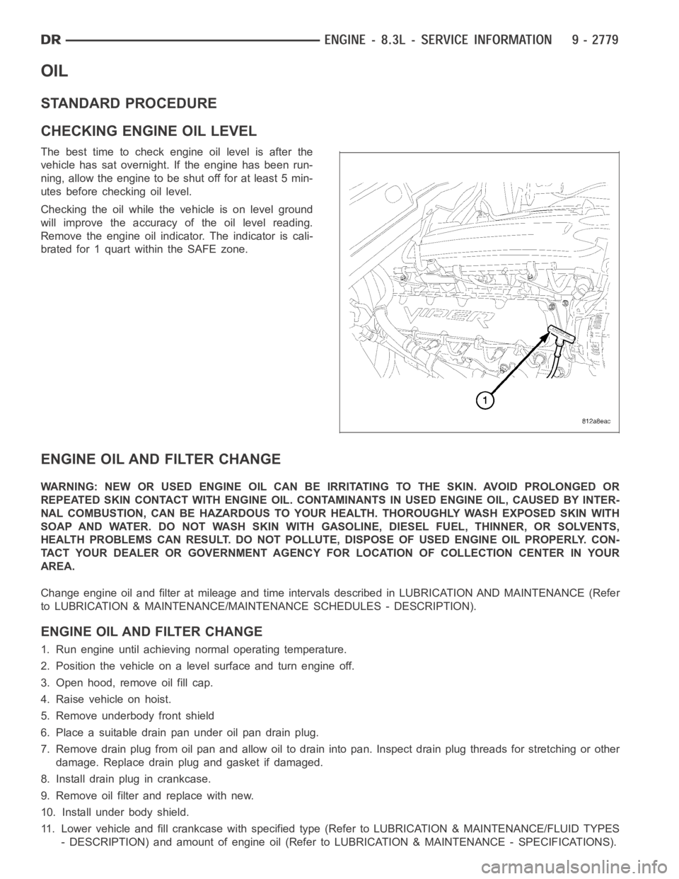
Remove the engine oil indicator. The indicator is cali-
brated for 1 quart within the SAFE zone.
ENGINE OIL AND FILTER CHANGE
WARNING: NEW OR USED ENGINE OIL CAN BE IRRITATING TO THE SKIN. AVOID PROLONGED OR
REPEATED SKIN CONTACT WITH ENGINE OIL. CONTAMINANTS IN USED ENGINE OIL, CAUSED BY INTER-
NAL COMBUSTION, CAN BE HAZARDOUS TO YOUR HEALTH. THOROUGHLY WASH EXPOSED SKIN WITH
SOAP AND WATER. DO NOT WASH SKIN WITH GASOLINE, DIESEL FUEL, THINNER, OR SOLVENTS,
HEALTH PROBLEMS CAN RESULT. DO NOT POLLUTE, DISPOSE OF USED ENGINE OIL PROPERLY. CON-
TACT YOUR DEALER OR GOVERNMENT AGENCY FOR LOCATION OF COLLECTION CENTER INYOUR
AREA.
Change engine oil and filter at mileage and time intervals described in LUBRICATION AND MAINTENANCE (Refer
to LUBRICATION & MAINTENANCE/MAINTENANCE SCHEDULES - DESCRIPTION).
ENGINE OIL AND FILTER CHANGE
1. Run engine until achieving normal operating temperature.
2. Position the vehicle on a level surface and turn engine off.
3. Open hood, remove oil fill cap.
4. Raise vehicle on hoist.
5. Remove underbody front shield
6. Place a suitable drain pan under oil pan drain plug.
7. Remove drain plug from oil pan and allow oil to drain into pan. Inspect drain plug threads for stretching or other
damage. Replace drain plug and gasket if damaged.
8. Install drain plug in crankcase.
9. Remove oil filter and replace with new.
10. Install under body shield.
11. Lower vehicle and fill crankcase with specified type (Refer to LUBRICATION & MAINTENANCE/FLUID TYPES
- DESCRIPTION) and amount of engine oil (Refer to LUBRICATION & MAINTENANCE - SPECIFICATIONS).
Page 2104 of 5267
BLOCK-ENGINE
DESCRIPTION
The cylinder block is made of a sand-cast aluminum alloy. The cylinder block has interference-fit cast iron cylinder
liners. The cylinder liners are thermally installed during block manufacturing; they are not serviceable items.
Six iron main bearing caps use four bolts per cap; two vertical and two horizontal. A crankshaft oil scraper is
attached to the main bearing caps via extended main bearing cap bolts and nuts.
STANDARD PROCEDURE - CYLINDER BORE HONING
Before honing, stuff plenty of clean shop towels under
the bores and over the crankshaft to keep abrasive
materials from entering the crankshaft area.
1. Used carefully, the Cylinder Bore Sizing Hone
C-823, equipped with 220 grit stones, is the best
tool for this job. In addition to deglazing, it will
reduce taper and out-of-round, as well as removing
light scuffing, scoring and scratches. Usually, a few
strokes will clean up a bore and maintain the
required limits.
CAUTION: DO NOT use rigid type hones to remove
cylinder wall glaze.
2. Deglazing of the cylinder walls may be done if the
cylinder bore is straight and round. Use a cylinder
surfacing hone, Honing Tool C-3501, equipped with
280 grit stones (C-3501-3810). about 20-60
strokes, depending on the bore condition, will be
sufficient to provide a satisfactory surface. Using
honing oil C-3501-3880, or a light honing oil, avail-
able from major oil distributors.
CAUTION: DO NOT use engine or transmission oil, mineral spirits, or kerosene.
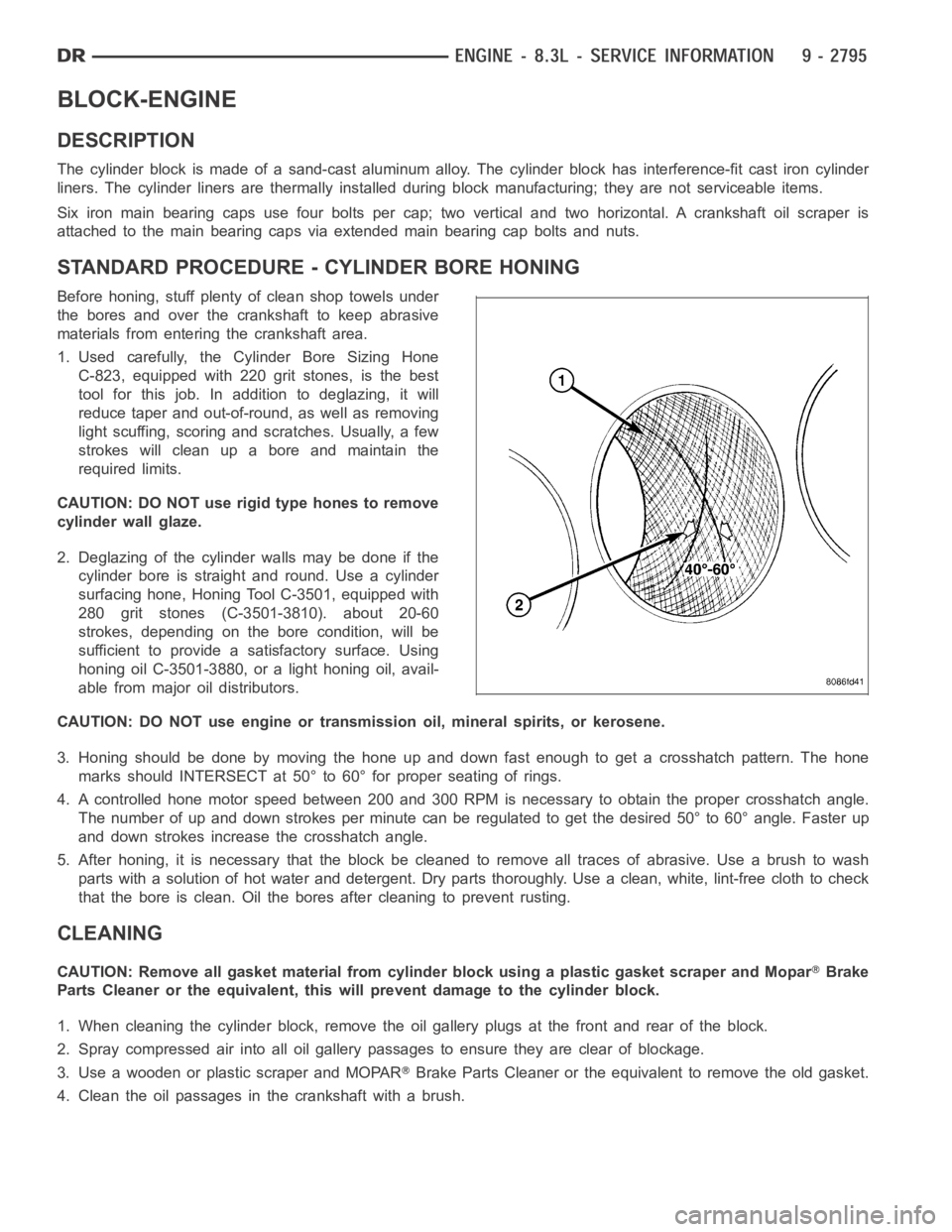
3. Honing should be done by moving the hone up and down fast enough to get a crosshatch pattern. The hone
marks should INTERSECT at 50° to 60° for proper seating of rings.
4. A controlled hone motor speed between 200 and 300 RPM is necessary to obtain the proper crosshatch angle.
The number of up and down strokes per minute can be regulated to get the desired 50° to 60° angle. Faster up
and down strokes increase the crosshatch angle.
5. After honing, it is necessary that the block be cleaned to remove all traces of abrasive. Use a brush to wash
parts with a solution of hot water and detergent. Dry parts thoroughly. Usea clean, white, lint-free cloth to check
that the bore is clean. Oil the bores after cleaning to prevent rusting.
CLEANING
CAUTION: Remove all gasket material from cylinder block using a plastic gasket scraper and MoparBrake
Parts Cleaner or the equivalent, this will prevent damage to the cylinder block.
1. When cleaning the cylinder block, remove the oil gallery plugs at the front and rear of the block.
2. Spray compressed air into all oil gallery passages to ensure they are clear of blockage.
3. Use a wooden or plastic scraper and MOPAR
Brake Parts Cleaner or the equivalent to remove the old gasket.
4. Clean the oil passages in the crankshaft with a brush.
Page 2206 of 5267
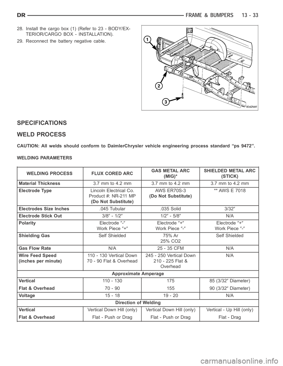
28. Install the cargo box (1) (Refer to 23 - BODY/EX-
TERIOR/CARGO BOX - INSTALLATION).
29. Reconnect the battery negative cable.
SPECIFICATIONS
WELD PROCESS
CAUTION: All welds should conform to DaimlerChrysler vehicle engineering process standard “ps 9472”.
WELDING PARAMETERS
WELDING PROCESS FLUX CORED ARCGAS METAL ARC
(MIG)*SHIELDED METAL ARC
(STICK)
Material Thickness3.7mmto4.2mm 3.7mmto4.2mm 3.7mmto4.2mm
Electrode TypeLincoln Electrical Co.
Product #: NR-211 MP
(Do Not Substitute)AWS ER70S-3
(Do Not Substitute)** AWS E 7018
Electrodes Size Inches.045 Tubular .035 Solid 3/32
Electrode Stick Out3/8-1/21/2-5/8N/A
PolarityElectrode
-
Work Piece+
Electrode+
Work Piece-
Electrode+
Work Piece-
Shielding GasSelf Shielded 75% Ar
25% CO2Self Shielded
Gas Flow RateN/A 25 - 35 CFM N/A
Wire Feed Speed
(inches per minute)110-130VerticalDown
70 - 90 Flat & Overhead245 - 250 Vertical Down
210 - 225 Flat &
OverheadN/A
Approximate Amperage
Ve r t i c a l110 - 130 175 85 (3/32
Diameter)
Flat & Overhead70 - 90 155 90 (3/32
Diameter)
Vo l t a g e15 - 18 19 - 20 N/A
Direction of Welding
Ve r t i c a lVertical Down Hill (only) Vertical Down Hill (only) Vertical - Up Hill (only)
Flat & OverheadFlat - Push or Drag Flat - Push or Drag Flat - Drag
Page 2386 of 5267
OPERATION
High-pressure fuel is supplied from the injection pump, through a high-pressure fuel line, into a fuel rail, through
high-pressure lines, through steel connectors and into the solenoid actuated fuel injector. The ECM actuates the
solenoid causing the needle valve to rise and fuel flows through the spray holes in the nozzle tip into the combus-
tion chamber.
Each fuel injector is connected to the fuel rail by a high-pressure fuel line and a steel connector. This steel con-
nector is positioned into the cylinder head and sealed with an O-ring. The connector is retained in the cylinder head
by a nut (fitting) that is threaded into the cylinder head.
The torquing force of this threaded nut (fitting) provides a sealing pressure between the fuel line connector and the
fuel injector.Retaining nut torque is very critical.If the nut (fitting) is under torqued, the mating surfaces will not
seal and a high-pressure fuel leak will result. If the fitting is over torqued, the connector and injector will deform and
also cause a high-pressure fuel leak. This leak will be inside the cylinderhead and will not be visible. The result will
be a possible fuel injector miss-fire and low power, or a no-start condition.
The fuel injectors use hole type nozzles. High-pressure flows into the side of the injector, the ECM activates the
solenoid causing the injector needle to lift and fuel to be injected. The clearances in the nozzle bore are extremely
small and any dirt or contaminants will cause the injector to stick. Because of this, it is very important to do a
thorough cleaning of any lines before opening up any fuel system component. Always cover or cap any open fuel
connections before a fuel system repair is performed.
Each fuel injector connector tube contains an edge filter that is designedto break up small contaminants before
entering the fuel injector.The edge filters are not a substitute for proper cleaning and covering of allfuel
system components during repair.
The bottom of each fuel injector is sealed to the cylinder head with a1.5mmthick copper shim (gasket). The correct
thickness shim must always be re-installed after removing an injector.
Fuel pressure in the injector circuit decreases after injection. The injector needle valve is immediately closed and
fuel flow into the combustion chamber is stopped. Exhaust gases are prevented from entering the injector nozzle by
the needle valve.
REMOVAL
CAUTION: Refer to Cleaning Fuel System Parts.
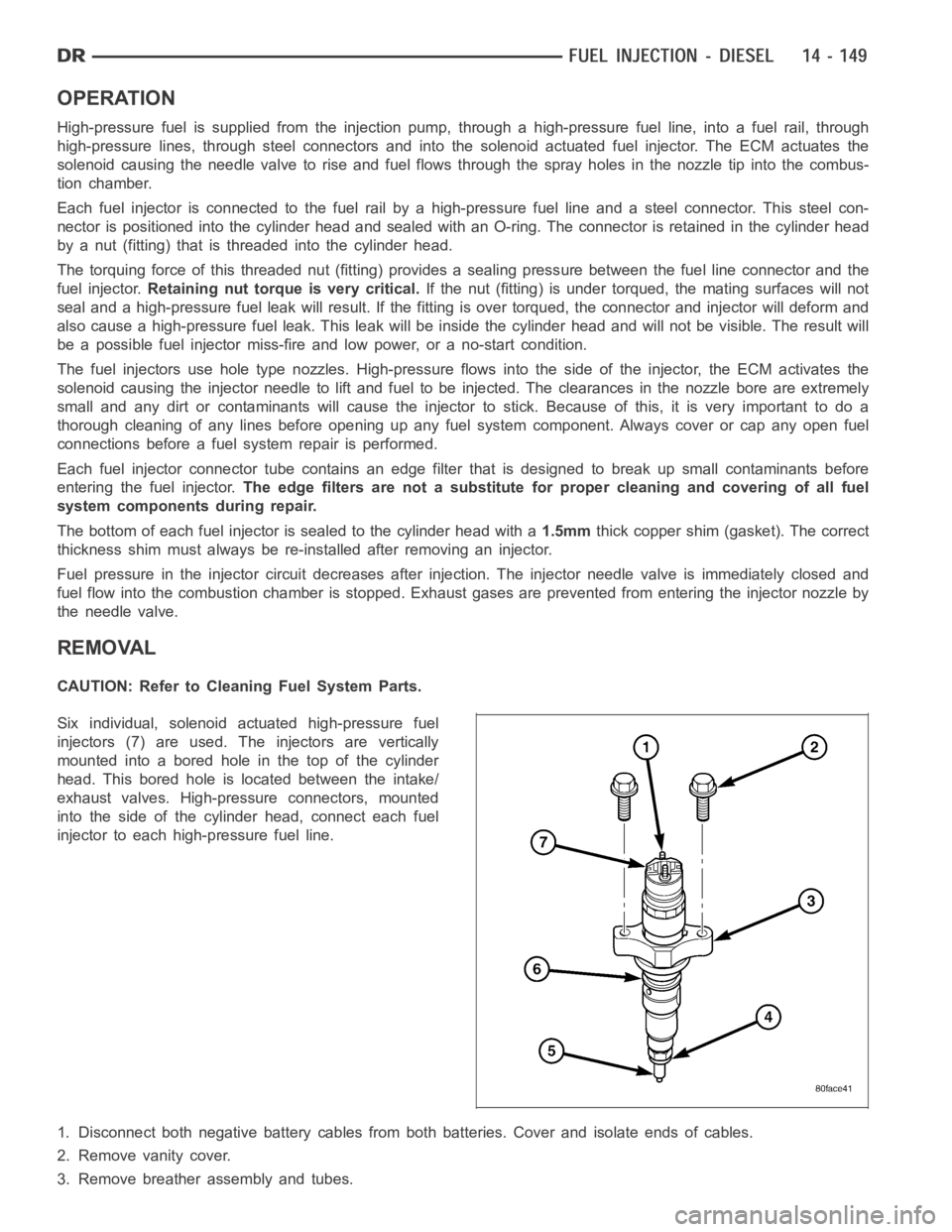
Six individual, solenoid actuated high-pressure fuel
injectors (7) are used. The injectors are vertically
mounted into a bored hole in the top of the cylinder
head. This bored hole is located between the intake/
exhaust valves. High-pressure connectors, mounted
into the side of the cylinder head, connect each fuel
injector to each high-pressure fuel line.
1. Disconnect both negative battery cables from both batteries. Cover andisolate ends of cables.
2. Remove vanity cover.
3. Remove breather assembly and tubes.
Page 3501 of 5267
CLEANING
Clean the valve housings, valves, plugs, springs, and separator plates with a standard parts cleaning solution only.
Do not use gasoline, kerosene, or any type of caustic solution.
Do not immerse any of the electrical components in cleaning solution. Clean the electrical components by wiping
them off with dry shop towels only.
Dry all except the electrical parts with compressed air. Make sure all passages are clean and free from obstructions.
Do not use rags or shop towels to dry or wipe off valve body components. Lint from these materials can
stick to valve body parts, interfere with valve operation, and clog filters and fluid passages.
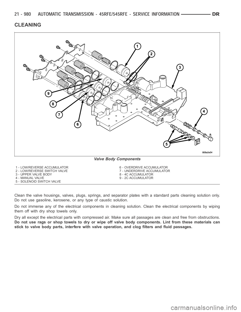
Valve Body Components
1 - LOW/REVERSE ACCUMULATOR 6 - OVERDRIVE ACCUMULATOR
2 - LOW/REVERSE SWITCH VALVE 7 - UNDERDRIVE ACCUMULATOR
3 - UPPER VALVE BODY 8 - 4C ACCUMULATOR
4 - MANUAL VALVE 9 - 2C ACCUMULATOR
5 - SOLENOID SWITCH VALVE
Page 3828 of 5267
The use of crocus cloth is permissible where necessary, providing it is usedcarefully.Whenusedonshafts,or
valves, use extreme care to avoid rounding off sharp edges. Sharp edges arevital as they prevent foreign matter
from getting between the valve and valve bore.
Do not reuse oil seals, gaskets, seal rings, or O-rings during overhaul. Replace these parts as a matter of course.
Also do not reuse snap rings or E-clips that are bent or distorted. Replace these parts as well.
ASSEMBLY
Do not allow dirt, grease, or foreign material to enter the case or transmission components during assembly. Keep
the transmission case and components clean. Also make sure the tools and workbench area used for reassembly
operations are equally clean.
Shop towels used for wiping off tools and your hands must be made fromlint freematerials. Lint will stick to trans-
mission parts and could interfere with valve operation or even restrict fluid passages.
Lubricate transmission clutch and gear components with Mopar
ATF +4 during reassembly. Soak clutch discs in
transmission fluid before installation.
Use petroleum jelly on piston seals and o-rings to ease installation. Petroleumjellycanalsobeusedtolubricate
and hold thrust washers and plates in position during assembly.
Do not use chassis grease, bearing grease, white grease, or similar lubricants on any part.These types of
lubricants can eventually block or restrict fluid passages and valve operation. Use petroleum jelly only.
Do not force parts into place. The transmission components and sub-assemblies are easily installed by hand when
properly aligned. If a part seems difficult to install, it is either misaligned or incorrectly assembled. Verify that thrust
washers, thrust plates and seal rings are correctly positioned.
The planetary geartrain, front/rear clutch assemblies and oil pump are all much easier to install when the transmis-
sion case is upright. Either tilt the case upward with wood blocks, or cut a hole in the bench large enough for the
intermediate shaft and rear support. Then lower the shaft and support intothe hole and support the rear of the case
directly on the bench.
FRONT/REAR SERVO
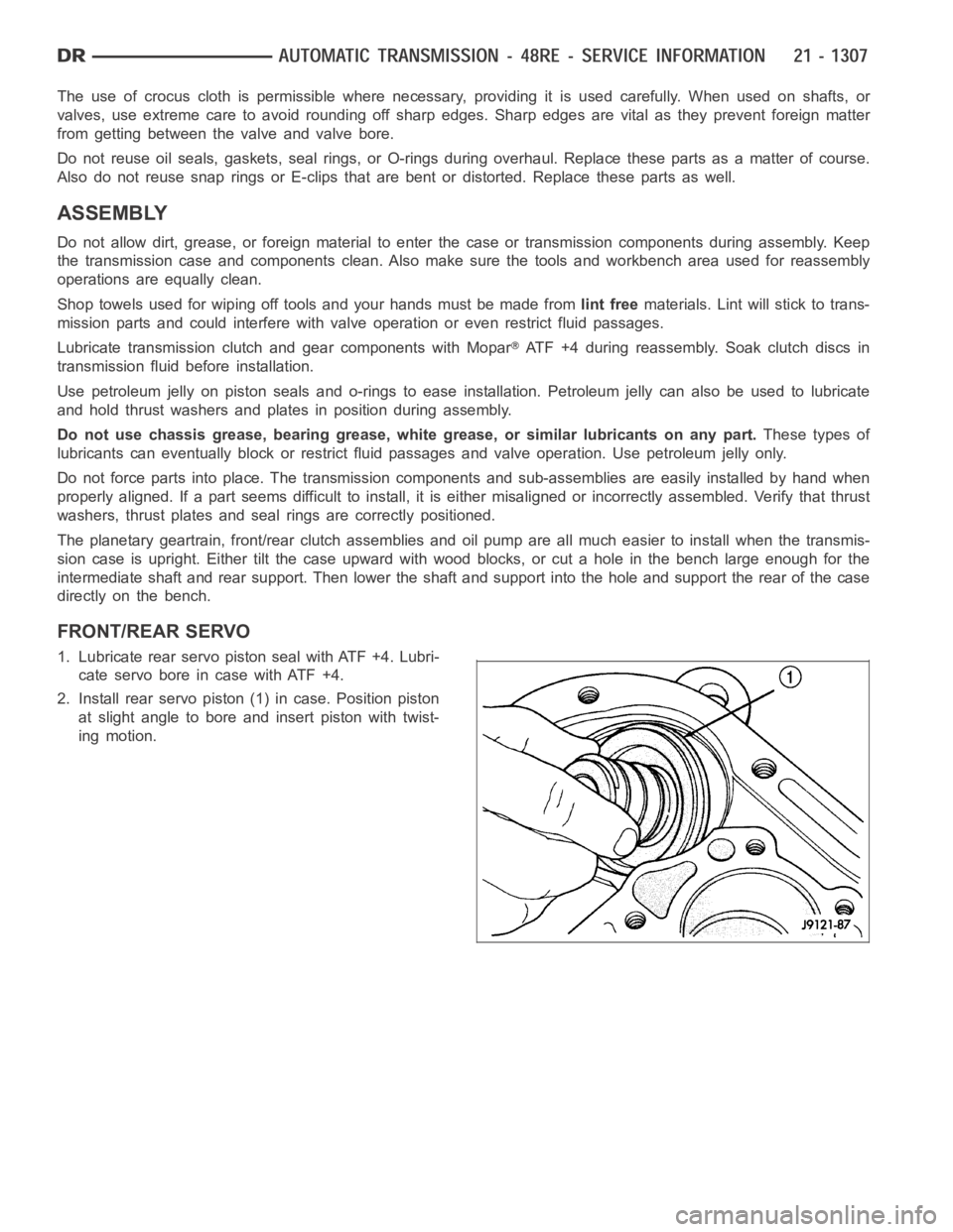
1. Lubricate rear servo piston seal with ATF +4. Lubri-
cateservoboreincasewithATF+4.
2. Install rear servo piston (1) in case. Position piston
at slight angle to bore and insert piston with twist-
ing motion.