2006 DODGE RAM SRT-10 gas type
[x] Cancel search: gas typePage 5169 of 5267
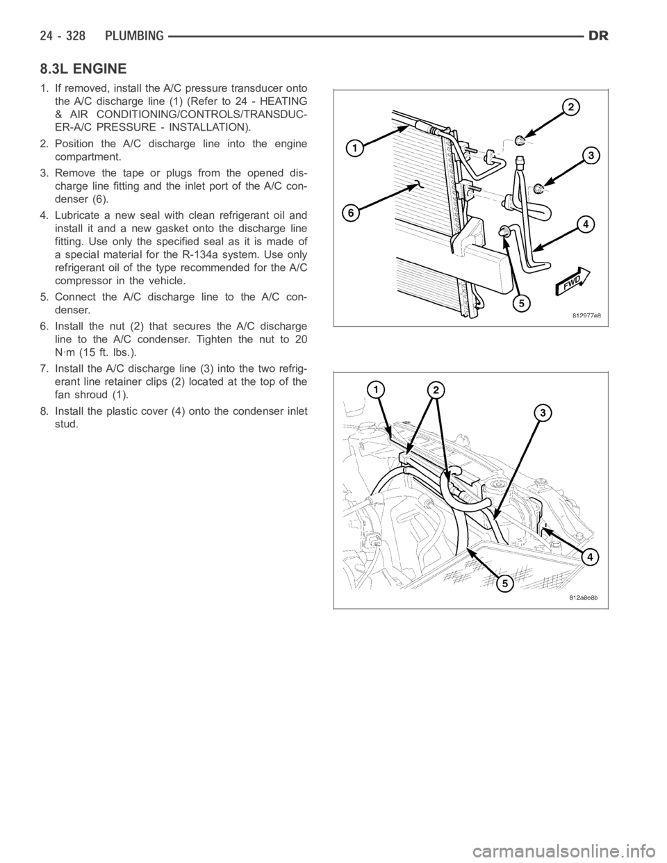
8.3L ENGINE
1. If removed, install the A/C pressure transducer onto
the A/C discharge line (1) (Refer to 24 - HEATING
& AIR CONDITIONING/CONTROLS/TRANSDUC-
ER-A/C PRESSURE - INSTALLATION).
2. Position the A/C discharge line into the engine
compartment.
3. Remove the tape or plugs from the opened dis-
charge line fitting and the inlet port of the A/C con-
denser (6).
4. Lubricate a new seal with clean refrigerant oil and
install it and a new gasket onto the discharge line
fitting. Use only the specified seal as it is made of
a special material for the R-134a system. Use only
refrigerant oil of the type recommended for the A/C
compressor in the vehicle.
5. Connect the A/C discharge line to the A/C con-
denser.
6. Install the nut (2) that secures the A/C discharge
line to the A/C condenser. Tighten the nut to 20
Nꞏm (15 ft. lbs.).
7. Install the A/C discharge line (3) into the two refrig-
erant line retainer clips (2) located at the top of the
fanshroud(1).
8. Install the plastic cover (4) onto the condenser inlet
stud.
Page 5170 of 5267
9. Remove the tape or plugs from the opened dis-
charge line fitting and compressor outlet port.
10. Lubricate a new seal with clean refrigerant oil and
install it and new gasket onto the discharge line
fitting. Use only the specified seal as it is made of
a special material for the R-134a system. Use
only refrigerant oil of the type recommended for
the A/C compressor in the vehicle.
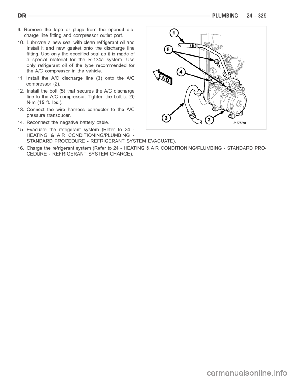
11. Install the A/C discharge line (3) onto the A/C
compressor (2).
12. Install the bolt (5) that secures the A/C discharge
line to the A/C compressor. Tighten the bolt to 20
Nꞏm (15 ft. lbs.).
13. Connect the wire harness connector to the A/C
pressure transducer.
14. Reconnect the negative battery cable.
15. Evacuate the refrigerant system (Refer to 24 -
HEATING & AIR CONDITIONING/PLUMBING -
STANDARD PROCEDURE - REFRIGERANT SYSTEM EVACUATE).
16. Charge the refrigerant system (Refer to 24 - HEATING & AIR CONDITIONING/PLUMBING - STANDARD PRO-
CEDURE - REFRIGERANT SYSTEM CHARGE).
Page 5171 of 5267
LINE-A/C LIQUID
DESCRIPTION
The liquid line is the refrigerant line that carries refrigerant from the A/C condenser to the A/C evaporator. The liquid
line for this model consist of two separate lines that connect to each otherusing a spring-lock type refrigerant line
coupler (Refer to 24 - HEATING & AIR CONDITIONING/PLUMBING/REFRIGERANT LINE COUPLER - DESCRIP-
TION). The liquid lines are made from light-weight aluminum, and use braze-less fittings.
The front half of the liquid line includes the high-side service port and the rear half of the liquid line contains the
fixed orifice tube.
CAUTION: Use only O-ring seals specified for the vehicle. Failure to use the correct O-ring seal will cause
the refrigerant system connections to leak.
The liquid line has no serviceable parts except for the rubber O-ring seals, high-side service port valve, cap and
secondary retaining clip. The O-ring seals used on the connections are made from a special type of rubber not
affected by R-134a refrigerant. The O-ring seals must be replaced whenever the liquid line is removed and installed.
If the liquid line is found to be leaking or is damaged, it must be replaced.
REMOVAL
3.7L/4.7L/5.7L/5.9L ENGINES
WARNING: Refer to the applicable warnings and cautions for this system before performing the following
operation (Refer to 24 - HEATING & AIR CONDITIONING/PLUMBING - WARNINGS) and (Refer to 24 - HEAT-
ING & AIR CONDITIONING/PLUMBING - CAUTIONS). Failure to follow the warnings and cautions could result
in possible personal injury or death.
NOTE:TheA/Cliquidlineisservicedintwosections.
FRONT SECTION
1. Recover the refrigerant from the refrigerant system
(Refer to 24 - HEATING & AIR CONDITIONING/
PLUMBING - STANDARD PROCEDURE -
REFRIGERANT SYSTEM RECOVERY).
2. Disconnect and isolate the negative battery cable.
3. If equipped with the diesel engine, remove the pas-
senger side battery (Refer to 8 - ELECTRICAL/
BATTERY SYSTEM/BATTERY - REMOVAL).
4. If equipped with a gasoline engine, remove the air
filter housing and mounting bracket (Refer to 9 -
ENGINE/AIR INTAKE SYSTEM/AIR FILTER
HOUSING - REMOVAL).
5. Remove the plastic cover from the condenser out-
let stud.
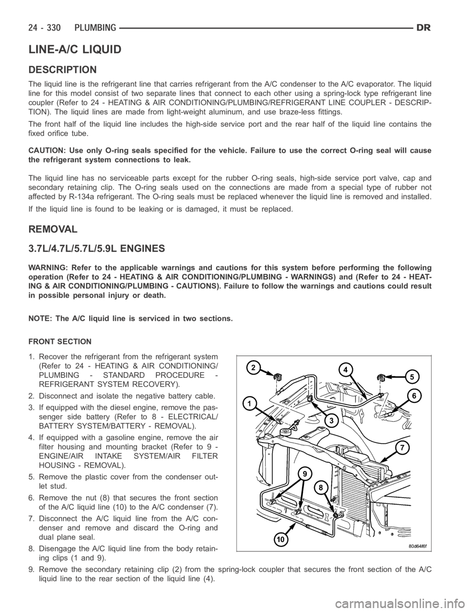
6. Remove the nut (8) that secures the front section
of the A/C liquid line (10) to the A/C condenser (7).
7. Disconnect the A/C liquid line from the A/C con-
denser and remove and discard the O-ring and
dual plane seal.
8. Disengage the A/C liquid line from the body retain-
ing clips (1 and 9).
9. Remove the secondary retaining clip (2) from the spring-lock coupler that secures the front section of the A/C
liquid line to the rear section of the liquid line (4).
Page 5174 of 5267
10. Remove the rear section of the A/C liquid line from the engine compartment.
INSTALLATION
3.7L/4.7L/5.7L/5.9L ENGINES
NOTE:TheA/Cliquidlineisservicedintwosections.
FRONT SECTION
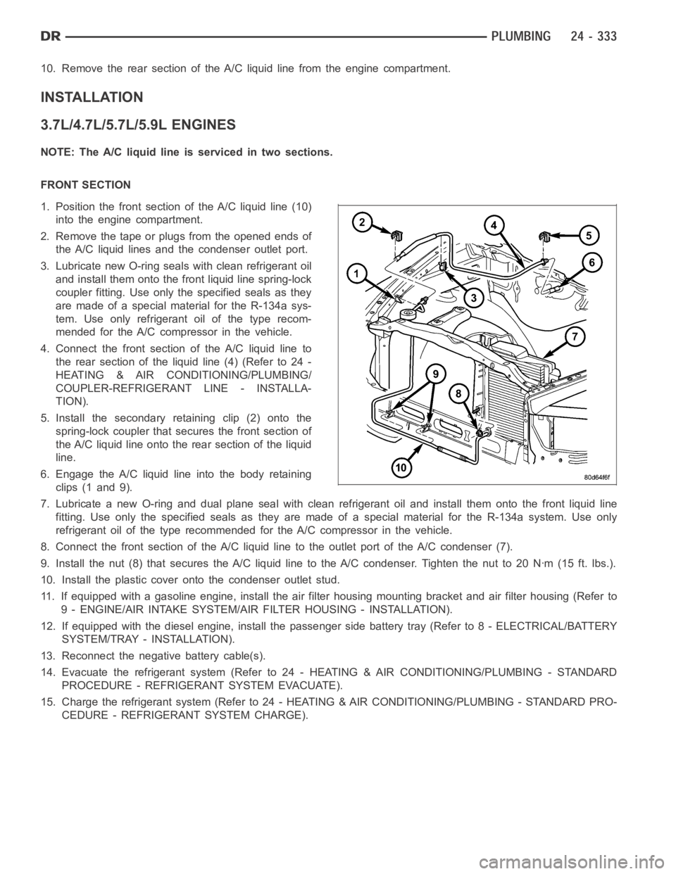
1. Position the front section of the A/C liquid line (10)
into the engine compartment.
2. Remove the tape or plugs from the opened ends of
the A/C liquid lines and the condenser outlet port.
3. Lubricate new O-ring seals with clean refrigerant oil
and install them onto the front liquid line spring-lock
coupler fitting. Use only the specified seals as they
are made of a special material for the R-134a sys-
tem. Use only refrigerant oil of the type recom-
mended for the A/C compressor in the vehicle.
4. Connect the front section of the A/C liquid line to
the rear section of the liquid line (4) (Refer to 24 -
HEATING & AIR CONDITIONING/PLUMBING/
COUPLER-REFRIGERANT LINE - INSTALLA-
TION).
5. Install the secondary retaining clip (2) onto the
spring-lock coupler that secures the front section of
the A/C liquid line onto the rear section of the liquid
line.
6. Engage the A/C liquid line into the body retaining
clips (1 and 9).
7. Lubricate a new O-ring and dual plane seal with clean refrigerant oil andinstall them onto the front liquid line
fitting. Use only the specified seals as they are made of a special materialfor the R-134a system. Use only
refrigerant oil of the type recommended for the A/C compressor in the vehicle.
8. Connect the front section of the A/C liquid line to the outlet port of the A/C condenser (7).
9. Install the nut (8) that secures the A/C liquid line to the A/C condenser.Tighten the nut to 20 Nꞏm (15 ft. lbs.).
10. Install the plastic cover onto the condenser outlet stud.
11. If equipped with a gasoline engine, install the air filter housing mounting bracket and air filter housing (Refer to
9 - ENGINE/AIR INTAKE SYSTEM/AIR FILTER HOUSING - INSTALLATION).
12. If equipped with the diesel engine, install the passenger side batterytray (Refer to 8 - ELECTRICAL/BATTERY
SYSTEM/TRAY - INSTALLATION).
13. Reconnect the negative battery cable(s).
14. Evacuate the refrigerant system (Refer to 24 - HEATING & AIR CONDITIONING/PLUMBING - STANDARD
PROCEDURE - REFRIGERANT SYSTEM EVACUATE).
15. Charge the refrigerant system (Refer to 24 - HEATING & AIR CONDITIONING/PLUMBING - STANDARD PRO-
CEDURE - REFRIGERANT SYSTEM CHARGE).
Page 5175 of 5267
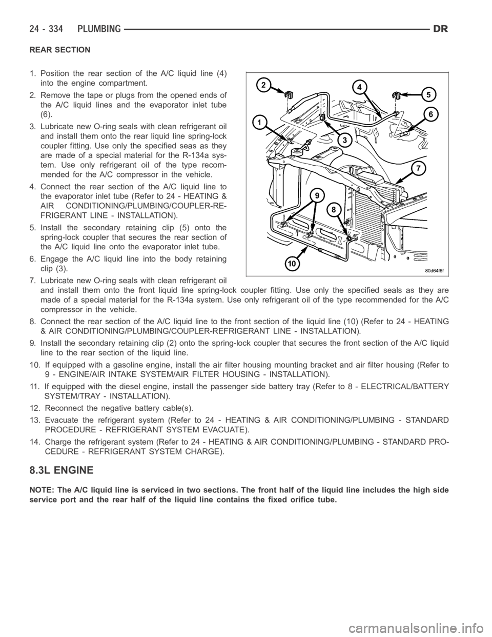
REAR SECTION
1. Position the rear section of the A/C liquid line (4)
into the engine compartment.
2. Remove the tape or plugs from the opened ends of
the A/C liquid lines and the evaporator inlet tube
(6).
3. Lubricate new O-ring seals with clean refrigerant oil
and install them onto the rear liquid line spring-lock
coupler fitting. Use only the specified seas as they
are made of a special material for the R-134a sys-
tem. Use only refrigerant oil of the type recom-
mended for the A/C compressor in the vehicle.
4. Connect the rear section of the A/C liquid line to
the evaporator inlet tube (Refer to 24 - HEATING &
AIR CONDITIONING/PLUMBING/COUPLER-RE-
FRIGERANT LINE - INSTALLATION).
5. Install the secondary retaining clip (5) onto the
spring-lock coupler that secures the rear section of
the A/C liquid line onto the evaporator inlet tube.
6. Engage the A/C liquid line into the body retaining
clip (3).
7. Lubricate new O-ring seals with clean refrigerant oil
and install them onto the front liquid line spring-lock coupler fitting. Use only the specified seals as they are
made of a special material for the R-134a system. Use only refrigerant oil of the type recommended for the A/C
compressor in the vehicle.
8. Connect the rear section of the A/C liquid line to the front section of theliquid line (10) (Refer to 24 - HEATING
& AIR CONDITIONING/PLUMBING/COUPLER-REFRIGERANT LINE - INSTALLATION).
9. Install the secondary retaining clip (2) onto the spring-lock coupler that secures the front section of the A/C liquid
line to the rear section of the liquid line.
10. If equipped with a gasoline engine, install the air filter housing mounting bracket and air filter housing (Refer to
9 - ENGINE/AIR INTAKE SYSTEM/AIR FILTER HOUSING - INSTALLATION).
11. If equipped with the diesel engine, install the passenger side batterytray (Refer to 8 - ELECTRICAL/BATTERY
SYSTEM/TRAY - INSTALLATION).
12. Reconnect the negative battery cable(s).
13. Evacuate the refrigerant system (Refer to 24 - HEATING & AIR CONDITIONING/PLUMBING - STANDARD
PROCEDURE - REFRIGERANT SYSTEM EVACUATE).
14. Charge the refrigerant system (Refer to 24 - HEATING & AIR CONDITIONING/PLUMBING - STANDARD PRO-
CEDURE - REFRIGERANT SYSTEM CHARGE).
8.3L ENGINE
NOTE: The A/C liquid line is serviced in two sections. The front half of the liquid line includes the high side
service port and the rear half of the liquid line contains the fixed orificetube.
Page 5176 of 5267
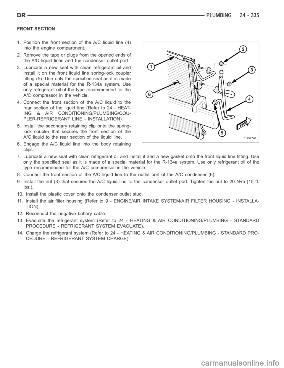
FRONT SECTION
1. Position the front section of the A/C liquid line (4)
into the engine compartment.
2. Remove the tape or plugs from the opened ends of
the A/C liquid lines and the condenser outlet port.
3. Lubricate a new seal with clean refrigerant oil and
install it on the front liquid line spring-lock coupler
fitting (5). Use only the specified seal as it is made
of a special material for the R-134a system. Use
only refrigerant oil of the type recommended for the
A/C compressor in the vehicle.
4. Connect the front section of the A/C liquid to the
rearsectionoftheliquidline(Referto24-HEAT-
ING & AIR CONDITIONING/PLUMBING/COU-
PLER-REFRIGERANT LINE - INSTALLATION).
5. Install the secondary retaining clip onto the spring-
lock coupler that secures the front section of the
A/C liquid to the rear section of the liquid line.
6. Engage the A/C liquid line into the body retaining
clips.
7. Lubricate a new seal with clean refrigerant oil and install it and a new gasket onto the front liquid line fitting. Use
only the specified seal as it is made of a special material for the R-134a system. Use only refrigerant oil of the
type recommended for the A/C compressor in the vehicle.
8. Connect the front section of the A/C liquid line to the outlet port of the A/C condenser (6).
9. Install the nut (3) that secures the A/C liquid line to the condenser outlet port. Tighten the nut to 20 Nꞏm (15 ft.
lbs.).
10. Install the plastic cover onto the condenser outlet stud.
11. Install the air filter housing (Refer to 9 - ENGINE/AIR INTAKE SYSTEM/AIR FILTER HOUSING - INSTALLA-
TION).
12. Reconnect the negative battery cable.
13. Evacuate the refrigerant system (Refer to 24 - HEATING & AIR CONDITIONING/PLUMBING - STANDARD
PROCEDURE - REFRIGERANT SYSTEM EVACUATE).
14. Charge the refrigerant system (Refer to 24 - HEATING & AIR CONDITIONING/PLUMBING - STANDARD PRO-
CEDURE - REFRIGERANT SYSTEM CHARGE).
Page 5190 of 5267
REFRIGERANT-A/C
DESCRIPTION
The refrigerant used in this air conditioning system is a HydroFluoroCarbon (HFC), type R-134a. Unlike R-12, which
is a ChloroFluoroCarbon (CFC), R-134a refrigerant does not contain ozone-depleting chlorine. R-134a refrigerant is
a non-toxic, non-flammable, clear, and colorless liquefied gas.
Even though R-134a does not contain chlorine, it must be reclaimed and recycled just like CFC-type refrigerants.
This is because R-134a is a greenhouse gas and can contribute to global warming.
OPERATION
R-134a refrigerant is not compatiblewith R-12 refrigerant in an A/C system. Even a small amount of R-12 refrigerant
added to an R-134a refrigerant system will cause A/C compressor failure, refrigerant oil sludge or poor A/C system
performance. In addition, the polyalkylene glycol (PAG) synthetic refrigerant oils used in an R-134a refrigerant sys-
tem are not compatible with the mineral-based refrigerant oils used in an R-12 refrigerant system.
R-134a refrigerant system service ports, service tool couplers and refrigerant dispensing bottles have all been
designed with unique fittings to ensure that an R-134a refrigerant systemis not accidentally contaminated with the
wrong refrigerant (R-12). There are also labels posted in the engine compartment of the vehicle and on the A/C
compressor to identify that the A/C system is equipped with R-134a refrigerant.
Page 5196 of 5267
CATALYST MONITOR
To comply with clean air regulations, vehicles are equipped with catalytic converters. These converters reduce the
emission of hydrocarbons, oxides of nitrogen and carbon monoxide.
Normal vehicle miles or engine misfire can cause a catalyst to decay. This can increase vehicle emissions and
deteriorate engine performance, driveability and fuel economy.
The catalyst monitor uses dual oxygen sensors (O2S’s) to monitor the efficiency of the converter. The dual O2S’s
sensor strategy is based on the fact that as a catalyst deteriorates, its oxygen storage capacity and its efficiency are
both reduced. By monitoring the oxygen storage capacity of a catalyst, itsefficiency can be indirectly calculated. The
upstream O2S is used to detect the amount of oxygen in the exhaust gas beforethe gas enters the catalytic con-
verter. The PCM calculates the A/F mixture from the output of the O2S. A low voltage indicates high oxygen content
(lean mixture). A high voltage indicates a low content of oxygen (rich mixture).
When the upstream O2S detects a lean condition, there is an abundance of oxygen in the exhaust gas. A function-
ing converter would store this oxygen so it can use it for the oxidation of HCand CO. As the converter absorbs the
oxygen, there will be a lack of oxygen downstream of the converter. The output of the downstream O2S will indicate
limited activity in this condition.
As the converter loses the ability to store oxygen, the condition can be detected from the behavior of the down-
stream O2S. When the efficiency drops, no chemical reaction takes place. This means the concentration of oxygen
will be the same downstream as upstream. The output voltage of the downstream O2S copies the voltage of the
upstream sensor. The only difference is a time lag (seen by the PCM) betweenthe switching of the O2S’s.
To monitor the system, the number of lean-to-rich switches of upstream anddownstream O2S’s is counted. The
ratio of downstream switches to upstream switches is used to determine whether the catalyst is operating properly.
An effective catalyst will have fewer downstream switches than it has upstream switches i.e., a ratio closer to zero.
For a totally ineffective catalyst, this ratio will be one-to-one, indicating that no oxidation occurs in the device.
The system must be monitored so that when catalyst efficiency deteriorates and exhaust emissions increase to over
the legal limit, the MIL will be illuminated.
TRIP DEFINITION
The term “Trip” has different meanings depending on what the circumstances are. If the MIL (Malfunction Indicator
Lamp) is OFF, a Trip is defined as when the Oxygen Sensor Monitor and the Catalyst Monitor have been completed
in the same drive cycle.
When any Emission DTC is set, the MIL on the dash is turned ON. When the MIL is ON, it takes 3 good trips to turn
the MIL OFF. In this case, it depends on what type of DTC is set to know what a “Trip” is.
For the Fuel Monitor or Mis-Fire Monitor (continuous monitor), the vehicle must be operated in the “Similar Condition
Window” for a specified amount of time to be considered a Good Trip.
If a Non-Continuous OBDII Monitor fails twice in a row and turns ON the MIL, re-running that monitor which previ-
ously failed, on the next start-up and passing the monitor, is considered tobeaGoodTrip.Thesewillincludethe
following:
Oxygen Sensor
Catalyst Monitor
Purge Flow Monitor
Leak Detection Pump Monitor (if equipped)
EGR Monitor (if equipped)
Oxygen Sensor Heater Monitor
If any other Emission DTC is set (not an OBDII Monitor), a Good Trip is considered to be when the Oxygen Sensor
Monitor and Catalyst Monitor have been completed; or 2 Minutes of engine run time if the Oxygen Sensor Monitor
or Catalyst Monitor have been stopped from running.
It can take up to 2 Failures in a row to turn on the MIL. After the MIL is ON, it takes3GoodTripstoturntheMIL
OFF. After the MIL is OFF, the PCM will self-erase the DTC after 40 Warm-up cycles. A Warm-up cycle is counted
when the ECT (Engine Coolant Temperature Sensor) has crossed 160°F (71.1C) and has risen by at least 40°F
(4.4°C) since the engine has been started.