2006 DODGE RAM SRT-10 check transmission fluid
[x] Cancel search: check transmission fluidPage 2664 of 5267
MANUAL TRANSMISSION-T56 - SERVICE INFORMATION
DIAGNOSIS AND TESTING
MANUAL TRANSMISSION - T56
LOW LUBRICANT LEVEL
A low transmission lubricant level is generally the result of a leak, inadequate lubricant fill or incorrect lubricant level
check.
Rear transmission leakswill be from the oil seals or component mating surfaces.
Front transmission leakswill be from the front bearing retainer or retainer seal. Lubricant may dripfromtheclutch
housing after extended operation. If leak is severe, it may contaminate the clutch disc.
Lubricant level checkcan only be made when the vehicle is level and allowing the lubricant to settle for a minute
before checking. This will ensure an accurate check and avoid an underfillor overfill condition.
HARD SHIFTING
Hard shifting is usually caused by low lubricant level, improper or contaminated lubricants. This will cause noise,
excessive wear, internal bind, and hard shifting. Substantial lubricantleaks can result in gear, shift rail, synchro, and
bearing damage. The first indications of component damage is usually hardshifting and noise.
Shift component damage, clutch adjustment, worn pressure plate or disc are also causes of increased shift effort. If
clutch problem is advanced, gear clash during shifts can result. Worn or damaged synchro rings can cause gear
clash when shifting into any forward gear. In some new or rebuilt transmissions, new synchro rings may tend to stick
slightly causing hard or noisy shifts. In most cases, this condition will decline as the rings wear-in.
TRANSMISSION NOISE
Most manual transmissions make some noise during normal operation. Rotating gears generate a mild whine that is
audible, but generally only at extreme speeds.
Severe, highly audible transmission noise is generally the initial indicator of a lubricant problem. Insufficient,
improper or contaminated lubricant will promote rapid wear of gears, synchros, shift rails, forks and bearings. The
overheating caused by a lubricant problem, can also lead to gear and bearing damage.
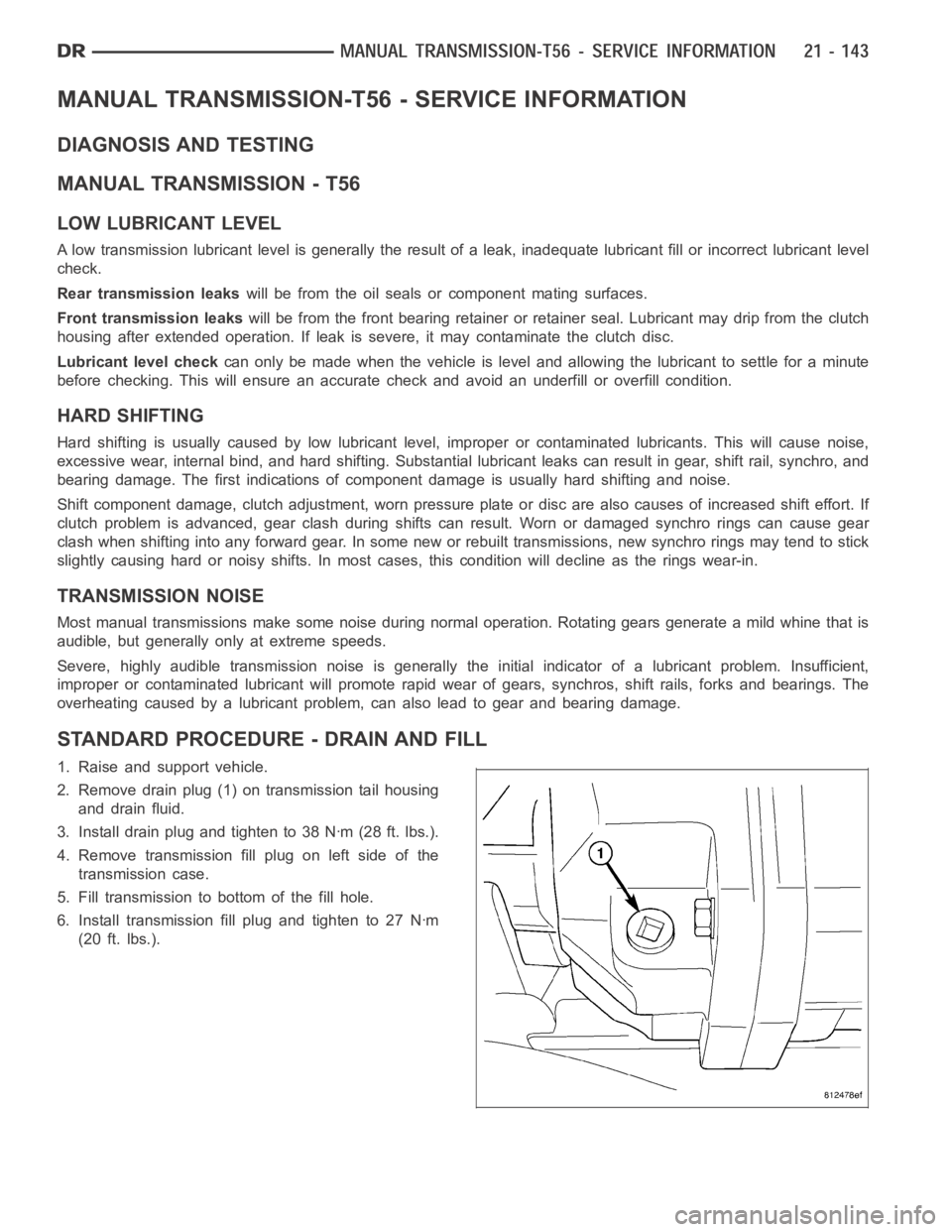
STANDARD PROCEDURE - DRAIN AND FILL
1. Raise and support vehicle.
2. Remove drain plug (1) on transmission tail housing
and drain fluid.
3. Install drain plug and tighten to 38 Nꞏm (28 ft. lbs.).
4. Remove transmission fill plug on left side of the
transmission case.
5. Fill transmission to bottom of the fill hole.
6. Install transmission fill plug and tighten to 27 Nꞏm
(20 ft. lbs.).
Page 2719 of 5267
SEAL-EXTENSION HOUSING
REMOVAL
NOTE: If extension housing slip yoke bushing is
worn the housing must be replaced,
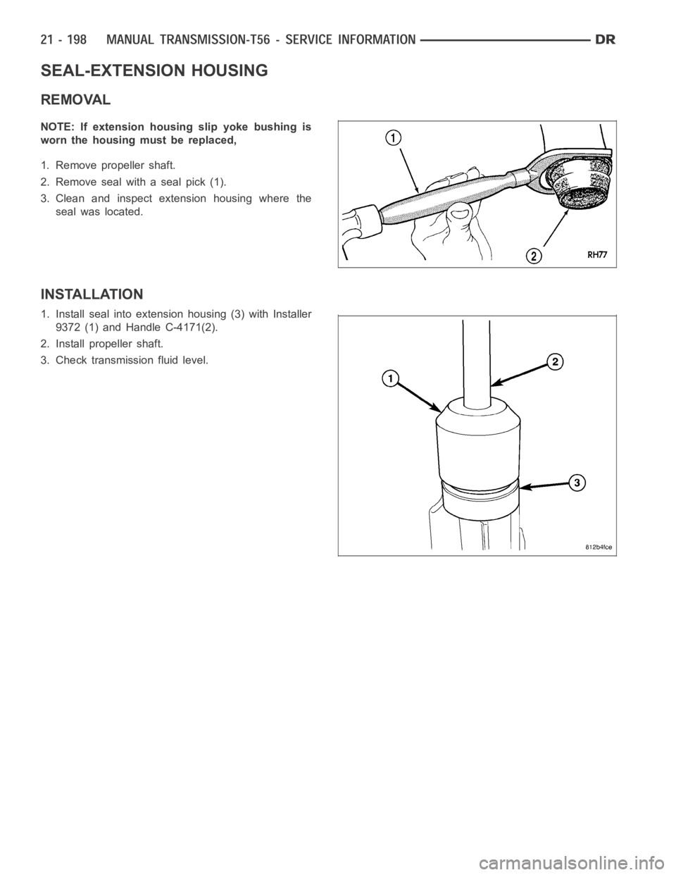
1. Remove propeller shaft.
2. Remove seal with a seal pick (1).
3. Clean and inspect extension housing where the
seal was located.
INSTALLATION
1. Install seal into extension housing (3) with Installer
9372 (1) and Handle C-4171(2).
2. Install propeller shaft.
3. Check transmission fluid level.
Page 2721 of 5267
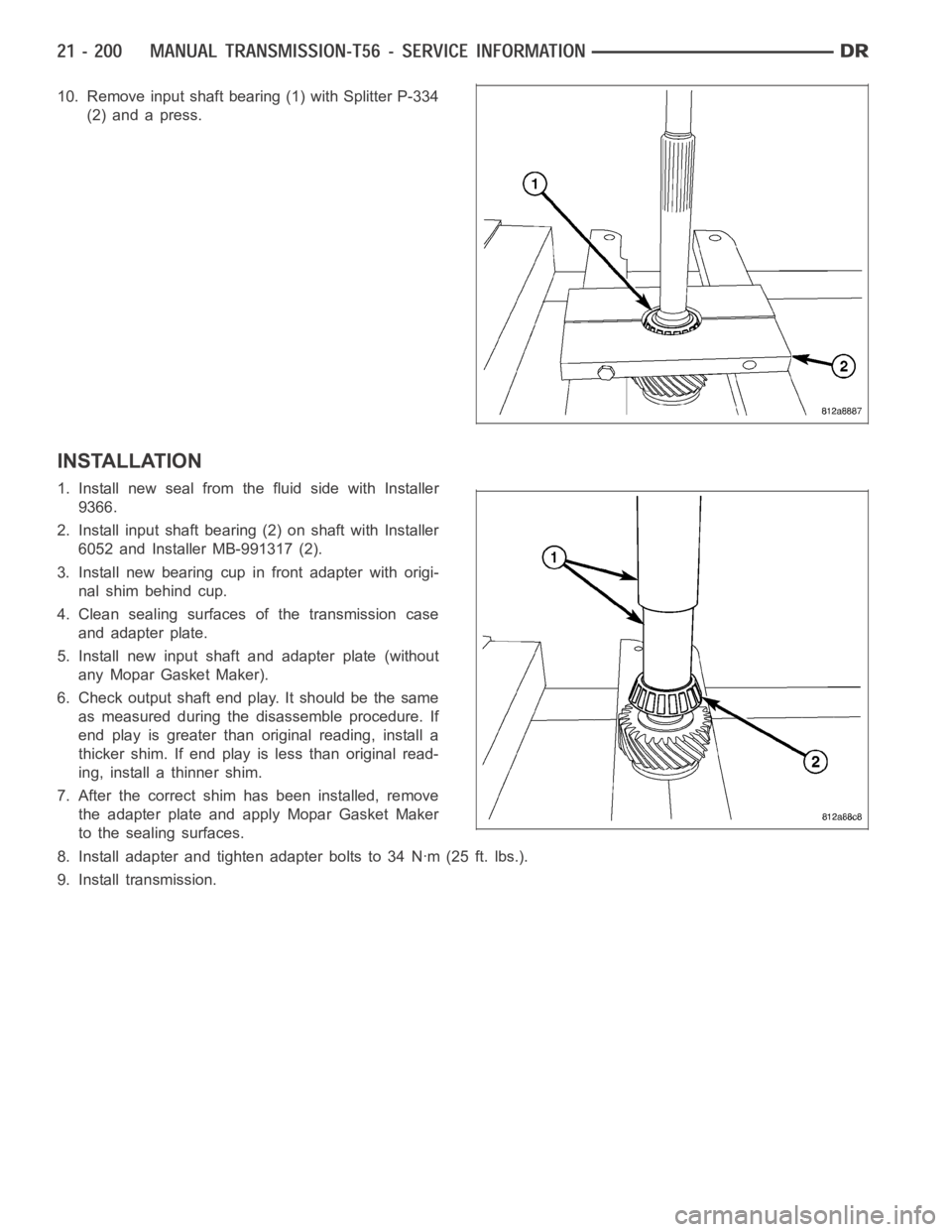
10. Remove input shaft bearing (1) with Splitter P-334
(2) and a press.
INSTALLATION
1. Install new seal from the fluid side with Installer
9366.
2. Install input shaft bearing (2) on shaft with Installer
6052 and Installer MB-991317 (2).
3. Install new bearing cup in front adapter with origi-
nal shim behind cup.
4. Clean sealing surfaces of the transmission case
and adapter plate.
5. Install new input shaft and adapter plate (without
any Mopar Gasket Maker).
6. Check output shaft end play. It should be the same
as measured during the disassemble procedure. If
end play is greater than original reading, install a
thicker shim. If end play is less than original read-
ing, install a thinner shim.
7. After the correct shim has been installed, remove
the adapter plate and apply Mopar Gasket Maker
to the sealing surfaces.
8. Install adapter and tighten adapter bolts to 34 Nꞏm (25 ft. lbs.).
9. Install transmission.
Page 2747 of 5267
When Monitored:
Continuously with the ignition on and engine running.
Set Condition:
DTC will set when the transmission temperature does not reach a normal operating temperature within a given
time frame. Time is variable due to ambient temperature. Approximate DTC set time is 10 to 35 minutes. The
following are starting temperature to warm up times to set this DTC: starting temperature -40° C (-40° F) warm
up time 35 minutes, starting temperature -28° C ( -20° F) 25 minutes, starting temperature -6.6° C (20° F) 20
minutes, starting temperature 15.5 ° C (60° F) 10 minutes. When the fault isset, calculated temperature is
substituted for measured temperature, however the DTC is stored only after three consecutive occurrences.
Possible Causes
RELATED TRANSMISSION TEMPERATURE DTC’S PRESENT
TRANSMISSION TEMPERATURE SENSOR
POWERTRAIN CONTROL MODULE
Always perform the Pre-Diagnostic Troubleshooting procedure before proceeding. (Refer to 21 - TRANSMIS-
SION/TRANSAXLE/AUTOMATIC - 42RLE - STANDARD PROCEDURE)
Theory of Operation
The temperature sensor is used to sense the temperature of the transmission fluid. Transmission fluid temperature
can affect shift quality, torque converter operation and when or if some diagnostics are run. A failed temperature
sensor could affect the OBD diagnostics. If a problem occurs in the transmission temperature sensor circuit, trans-
mission temperature will be based on a calculated value.
Diagnostic Test
1.DETERMINE IF RELATED TRANSMISSION TEMPERATURE DTCS ARE PRESENT
With the scan tool, check Transmission DTCs.
Are there any other Transmission Temperature Sensor related DTCs present?
Ye s>>
Refer to the Transmission category and perform the appropriate diagnostic procedure.
No>>
Go To 2
2.CHECK TO SEE IF DTC IS ACTIVE
With the scan tool, view DTCs.
Is the status Active for this DTC or is the STARTS SINCE SET counter 2 or less?
Ye s>>
Go To 3
No>>
Go To 4
3.PCM AND WIRING
Turn the ignition off to the lock position.
Remove the Ignition Switch Feed fuse from the TIPM.
CAUTION: Removal of the Ignition Switch Feed fuse from the TIPM will prevent the vehicle from being
startedingear.
WARNING: The Ignition Switch Feed fuse must be removed from the TIPM. Failure to do so can result in
personal injury or death.
Install the Transmission Simulator,Miller tool #8333 and the ElectronicTransmission Adapter kit.
Ignition on, engine not running.
With the Transmission Simulator, turn the Input/Output switch to OFF.
With the scan tool, monitor the TRANS TEMP VOLTS while turning the ThermistorVoltageswitchtoallthreeposi-
tions on the Transmission Simulator.
Page 2750 of 5267
When Monitored:
Continuously with the ignition on and engine running.
Set Condition:
The DTC will set when the monitored Temperature Sensor voltage drops below0.078 volts for the period of
1.45 seconds. When the fault is set, calculated temperature is substituted for measured temperature, however
the fault code is stored only after three consecutive occurrences of the fault.
Possible Causes
RELATED DTCS PRESENT
(T54) TRANSMISSION TEMPERATURE SENSOR SIGNAL CIRCUIT SHORT TO GROUND
TRANSMISSION TEMPERATURE SENSOR
POWERTRAIN CONTROL MODULE
Always perform the Pre-Diagnostic Troubleshooting procedure before proceeding. (Refer to 21 - TRANSMIS-
SION/TRANSAXLE/AUTOMATIC - 42RLE - STANDARD PROCEDURE)
Theory of Operation
The temperature sensor is used to sense the temperature of the transmission fluid. Transmission fluid temperature
can affect shift quality, torque converter operation and when or if some diagnostics are run. A failed temperature
sensor could affect the OBD diagnostics. If a problem occurs in the transmission temperature sensor circuit, trans-
mission temperature will be based on a calculated value.
Diagnostic Test
1.DETERMINE IF RELATED DTCS ARE PRESENT
With the scan tool, check Transmission DTCs.
Are there any Speed Sensor DTCs present?
Ye s>>
Refer to the Transmission category and perform the appropriate diagnostic procedure.
No>>
Go To 2
2.CHECK TO SEE IF DTC IS ACTIVE
With the scan tool, view DTCs.
Is the status Active for this DTC or is the STARTS SINCE SET counter 2 or less?
Ye s>>
Go To 3
No>>
Go To 5
3.CHECK THE PCM AND WIRING WITH THE TRANSMISSION SIMULATOR
Turn the ignition off to the lock position.
Remove the Ignition Switch Feed fuse from the TIPM.
CAUTION: Removal of the Ignition Switch Feed fuse from the TIPM will prevent the vehicle from being
startedingear.
WARNING: The Ignition Switch Feed fuse must be removed from the TIPM. Failure to do so can result in
personal injury or death.
Install the Transmission Simulator,Miller tool #8333 and the ElectronicTransmission Adapter kit.
Ignition on, engine not running.
With the Transmission Simulator, turn the Input/Output switch to OFF.
With the scan tool, monitor the TRANS TEMP VOLTS while turning the ThermistorVoltageswitchtoallthreeposi-
tions on the Transmission Simulator.
Page 2753 of 5267
When Monitored:
Continuously with the ignition on and engine running.
Set Condition:
The DTC will set when the monitored Temperature Sensor voltage rises above4.94 volts for the period of 1.45
seconds. When the fault is set, calculated temperature is substituted formeasured temperature, however the
fault code is stored only after three consecutive occurrences of the fault.
Possible Causes
(K900) SENSOR GROUND OPEN
(T54) TRANSMISSION TEMPERATURE SENSOR SIGNAL CIRCUIT OPEN
(T54) TRANSMISSION TEMPERATURE SENSOR SIGNAL CIRCUIT SHORT TO VOLTAGE
TRANSMISSION TEMPERATURE SENSOR
POWERTRAIN CONTROL MODULE
Always perform the Pre-Diagnostic Troubleshooting procedure before proceeding. (Refer to 21 - TRANSMIS-
SION/TRANSAXLE/AUTOMATIC - 42RLE - STANDARD PROCEDURE)
Theory of Operation
The temperature sensor is used to sense the temperature of the transmission fluid. Transmission fluid temperature
can affect shift quality, torque converter operation and when or if some diagnostics are run. A failed temperature
sensor could affect the OBD diagnostics. If a problem occurs in the transmission temperature sensor circuit, trans-
mission temperature will be based on a calculated value.
1.CHECK TO SEE IF DTC IS CURRENT
With the scan tool, view DTCs.
Is the status Active for this DTC or is STARTS SINCE SET counter 2 or less?
Ye s>>
Go To 2
No>>
Go To 6
2.CHECK THE PCM AND WIRING WITH THE TRANSMISSION SIMULATOR
Turn the ignition off to the lock position.
Remove the Ignition Switch Feed fuse from the TIPM.
CAUTION: Removal of the Ignition Switch Feed fuse from the TIPM will prevent the vehicle from being
startedingear.
WARNING: The Ignition Switch Feed fuse must be removed from the TIPM. Failure to do so can result in
personal injury or death.
Install the Transmission Simulator,Miller tool #8333 and the ElectronicTransmission Adapter kit 8333-1A.
Ignition on, engine not running.
With the Transmission Simulator, turn the Input/Output switch to OFF.
With the scan tool, monitor the TRANS TEMP VOLTS while turning the ThermistorVoltageswitchtoallthreeposi-
tions on the Transmission Simulator.
Compare the scan tool readings with the numbers listed on the TransmissionSimulator.
Do the readings on the Transmission Simulator match the scan tool readings± 0.2 volts?
Ye s>>
Replace Transmission Solenoid/Pressure Switch Assembly per the ServiceInformation.
Perform 42RLE TRANSMISSION VERIFICATION TEST - VER 1. (Refer to 21 - TRANSMISSION/
TRANSAXLE/AUTOMATIC - 42RLE - STANDARD PROCEDURE)
No>>
Go To 3
Page 2757 of 5267
When Monitored:
Continuously with the ignition on and engine running.
Set Condition:
The DTC will set when the monitored Temperature Sensor voltage fluctuatesor changes abruptly within a pre-
determined period of time.
Possible Causes
TRANSMISSION TEMPERATURE SENSOR
POWERTRAIN CONTROL MODULE
Always perform the Pre-Diagnostic Troubleshooting procedure before proceeding. (Refer to 21 - TRANSMIS-
SION/TRANSAXLE/AUTOMATIC - 42RLE - STANDARD PROCEDURE)
Theory of Operation
The temperature sensor is used to sense the temperature of the transmission fluid. Transmission fluid temperature
can affect shift quality, torque converter operation and when or if some diagnostics are run. A failed temperature
sensor could affect the OBD diagnostics. If a problem occurs in the transmission temperature sensor circuit, trans-
mission temperature will be based on a calculated value.
1.CHECK TO SEE IF DTC IS CURRENT
With the scan tool, view DTCs.
Is the status Active for this DTC or is the STARTS SINCE SET counter 2 or less?
Ye s>>
Go To 2
No>>
Go To 3
2.CHECK THE PCM AND WIRING WITH THE TRANSMISSION SIMULATOR
Turn the ignition off to the lock position.
Remove the Ignition Switch Feed fuse from the TIPM.
CAUTION: Removal of the Ignition Switch Feed fuse from the TIPM will prevent the vehicle from being
startedingear.
WARNING: The Ignition Switch Feed fuse must be removed from the TIPM. Failure to do so can result in
personal injury or death.
Install the Transmission Simulator,Miller tool #8333 and the ElectronicTransmission Adapter kit.
Ignition on, engine not running.
With the Transmission Simulator, turn the Input/Output switch to OFF.
With the scan tool , monitor the TRANS TEMP VOLTS while turning the ThermistorVoltageswitchtoallthreeposi-
tions on the Transmission Simulator.
Compare the scan tool readings with the numbers listed on the TransmissionSimulator.
Do the readings on the Transmission Simulator match a non-fluctuating scan tool reading ± 0.2 volts?
Ye s>>
Replace Transmission Solenoid/Pressure Switch Assembly per the ServiceInformation.
Perform 42RLE TRANSMISSION VERIFICATION TEST - VER 1. (Refer to 21 - TRANSMISSION/
TRANSAXLE/AUTOMATIC - 42RLE - STANDARD PROCEDURE)
No>>
Using the schematics as a guide, check the Powertrain Control Module (PCM)terminals for corrosion,
damage, or terminal push out. Pay particular attention to all power and ground circuits. Check for any
Service Information Tune-ups or Service Bulletins for any possible causes that may apply. If no prob-
lems are found, replace the PCM per the Service Information. With the scan tool, perform QUICK
LEARN.
Perform 42RLE TRANSMISSION VERIFICATION TEST - VER 1. (Refer to 21 - TRANSMISSION/
TRANSAXLE/AUTOMATIC - 42RLE - STANDARD PROCEDURE)
Page 2816 of 5267
When Monitored:
Continuously while driving in a forward gear.
Set Condition:
The PCM continuously monitors Actual Line Pressure and compares it to DesiredLinePressure.IftheActual
Line Pressure is more than 10 psi below Desired Line Pressure, this DTC willset.
Possible Causes
CHECK FOR RELATED DTC’S
LOW FLUID LEVEL
(F856) 5-VOLT SUPPLY CIRCUIT OPEN
(F856) 5-VOLT SUPPLY CIRCUIT SHORT TO GROUND
(F856) 5-VOLT SUPPLY CIRCUIT SHORT TO VOLTAGE
(T118) PRESSURE CONTROL SOLENOID CONTROL CIRCUIT SHORT TO ANOTHER CIRCUIT
INTERNAL TRANSMISSION
LINE PRESSURE SENSOR
CRACKED, PLUGGED, OR MIS-INSTALLED PRIMARY OIL FILTER
STUCK OR STICKING MAIN REGULATOR VALVE
POWERTRAIN CONTROL MODULE
Always perform the 42RLE Pre-Diagnostic Troubleshooting procedure before proceeding. (Refer to 21 -
TRANSMISSION/TRANSAXLE/AUTOMATIC - 42RLE - STANDARD PROCEDURE)
Theory of Operation
Line pressure is measured by the Line Pressure Sensor (LPS) and regulationis achieved by changing the duty
cycle of the Pressure Control Solenoid (PCS) controlled by the Transmission Control System. (5% duty cycle =
solenoid off = Max line pressure, 62%duty cycle = solenoid on = Min line pressure). The Transmission Control
System calculates the desired line pressure based on inputs from both the engine and transmission.
The Transmission Control System calculates torque input to the transmission and uses it as the primary input to the
desired line pressure calculation. This is called Torque Based Line Pressure. In addition, the line pressure is set to
a preset level 827 or 931 kPa (120 or 135 psi) during shifts and in Park and Neutral to ensure consistent shift
quality. The desired line pressure is continuously being compared to the actual line pressure. If the actual line pres-
sure is consistently lower than the target while driving, the line pressure low DTC P0868 will set.
Diagnostic Test
1.CHECKFORRELATEDDTCS
With the scan tool, check for other transmission DTCs
Is the DTC P0932 present also?
Ye s>>
Refer to the Transmission category and perform the appropriate symptom.
No>>
Go To 2