Page 4619 of 5267
COVER-GUIDE MECHANISM
REMOVAL
1. Move the glass panel to the full closed position.
2. Slide sunshade rearward to the open position.
3. Separate the mechanism covers (2) from the tabs
(1) on the glass panel.
4. Hold both mechanism covers down and open the
sunroof fully.
5. Slide the mechanism covers (1) out the front of the
guide in the frame (2).
Page 4620 of 5267
INSTALLATION
1. With the sunroof in the open position, snap the mechanism cover (2) into the lower guide channel.
2. Hold down each cover and close the sunroof.
3. Snap the upper portion of the cover (2) into the retaining clips (1) on theglass panel between the locating fea-
tures.
Page 4621 of 5267
DEFLECTOR-WIND
REMOVAL
1. Open the sunroof fully.
2. Remove the strap screws (2) from the beam area
release the strap (3).
3. Rotate the deflector up and remove springs (2)
from the holes in the frame (1).
Page 4622 of 5267
INSTALLATION
1. Position the deflector spring arms (2) into the holes
of the frame (1).
2. Rotate the deflector down, attach the straps (3)
and install the strap screws (2) into the front beam.
3. Verify sunroof operation and alignment.
Page 4624 of 5267
INSTALLATION
1. Position glass panel on to mechanism lift arms.
CAUTION: Verify that the retaining tabs are located on the INSIDE of the guide mechanism arms.
2. Start the attaching screws (3).
3. Connect a 12v power supply and verify that the sunroof is in the closed position.
4. Adjust sunroof glass to fit flushwith roof line (Refer to 23 - BODY/SUNROOF/GLASS PANEL - ADJUSTMENTS).
5. Tighten the screws (3) to 3.5 Nꞏm (30 in. lbs.).
6. Position the mechanism covers (2) over the glass tabs (1) between the locating features and seat fully.
7. Verify sunroof operation and alignment.
Page 4625 of 5267

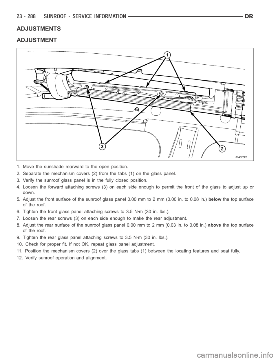
ADJUSTMENTS
ADJUSTMENT
1. Move the sunshade rearward to the open position.
2. Separate the mechanism covers (2) from the tabs (1) on the glass panel.
3. Verify the sunroof glass panel is in the fully closed position.
4. Loosen the forward attaching screws (3) on each side enough to permit thefront of the glass to adjust up or
down.
5. Adjust the front surface of the sunroof glass panel 0.00 mm to 2 mm (0.00 in.to0.08in.)belowthe top surface
of the roof.
6. Tighten the front glass panel attaching screws to 3.5 Nꞏm (30 in. lbs.).
7. Loosen the rear screws (3) on each side enough to make the rear adjustment.
8. Adjust the rear surface of the sunroof glass panel 0.00 mm to 2 mm (0.03 in.to 0.08 in.)abovethe top surface
of the roof.
9. Tighten the rear glass panel attaching screws to 3.5 Nꞏm (30 in. lbs.).
10. Check for proper fit. If not OK, repeat glass panel adjustment.
11. Position the mechanism covers (2) over the glass tabs (1) between the locating features and seat fully.
12. Verify sunroof operation and alignment.
Page 4626 of 5267
GUIDE-SUNROOF GLASS
REMOVAL
1. Place the sunroof in the vent position.
2. Remove the sunroof assembly. (Refer to 23 -
BODY/SUNROOF/ASSEMBLY-MODULE -
REMOVAL)
3. Remove the motor. (Refer to 8 - ELECTRICAL/
POWER TOP - SUNROOF SERVICE INFO/MO-
TOR/MODULE-SUNROOF - REMOVAL)
4. Remove the glass. (Refer to 23 - BODY/SUN-
ROOF/GLASS - REMOVAL)
5. Remove the wind deflector. (Refer to 23 - BODY/
SUNROOF/DEFLECTOR-WIND - REMOVAL)
6. Separate the drain channel arms (2) from the guide
mechanisms (1) one at a time.
CAUTION: Do not pry the channel arms apart at
the same time or you could break the drain chan-
nel.
7. Slide the drain channel rearward out of the way.
8. Remove the hard stop screw from the frame.
Page 4629 of 5267

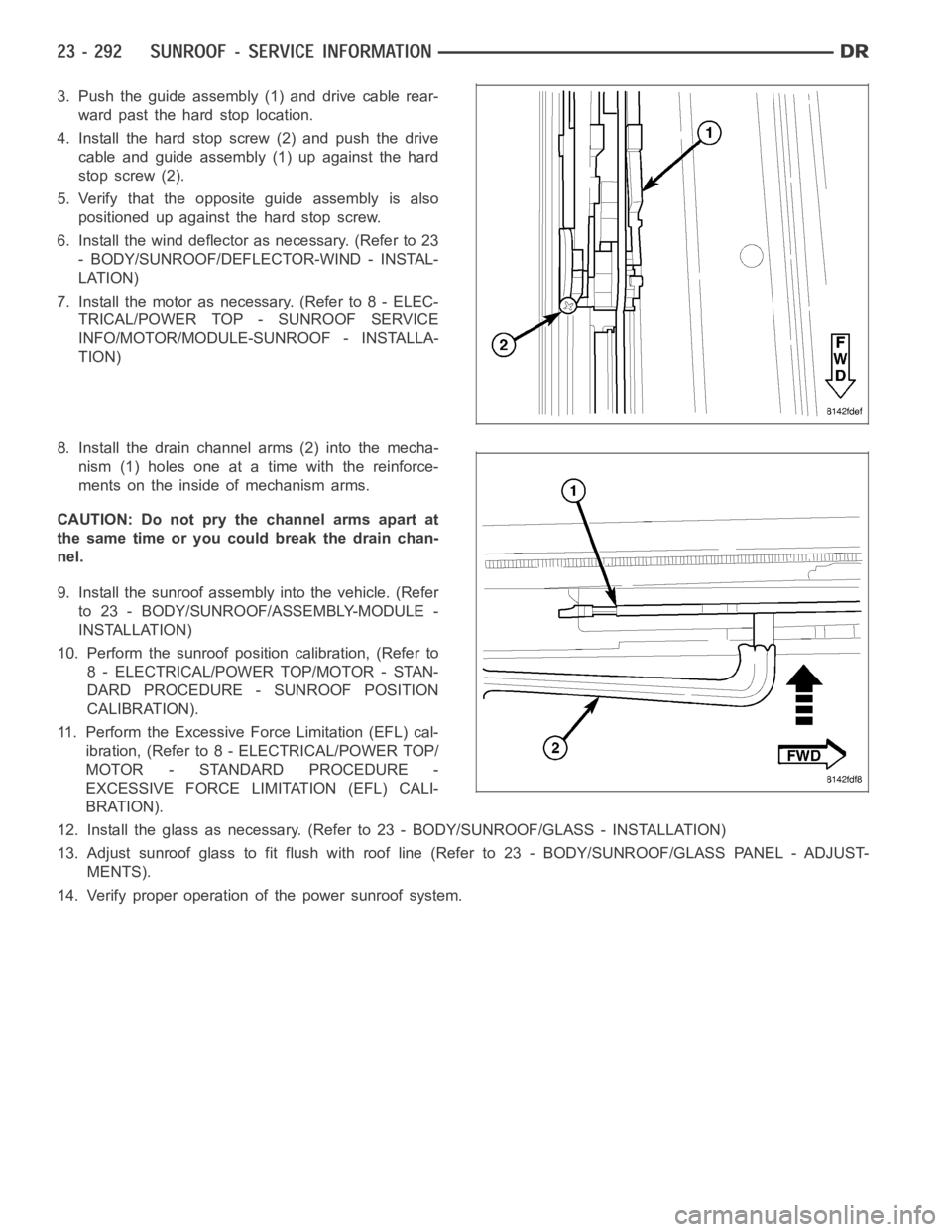
3. Push the guide assembly (1) and drive cable rear-
ward past the hard stop location.
4. Install the hard stop screw (2) and push the drive
cable and guide assembly (1) up against the hard
stop screw (2).
5. Verify that the opposite guide assembly is also
positioned up against the hard stop screw.
6. Install the wind deflector as necessary. (Refer to 23
- BODY/SUNROOF/DEFLECTOR-WIND - INSTAL-
LATION)
7. Install the motor as necessary. (Refer to 8 - ELEC-
TRICAL/POWER TOP - SUNROOF SERVICE
INFO/MOTOR/MODULE-SUNROOF - INSTALLA-
TION)
8. Install the drain channel arms (2) into the mecha-
nism (1) holes one at a time with the reinforce-
ments on the inside of mechanism arms.
CAUTION: Do not pry the channel arms apart at
the same time or you could break the drain chan-
nel.
9. Install the sunroof assembly into the vehicle. (Refer
to 23 - BODY/SUNROOF/ASSEMBLY-MODULE -
INSTALLATION)
10. Perform the sunroof position calibration, (Refer to
8 - ELECTRICAL/POWER TOP/MOTOR - STAN-
DARD PROCEDURE - SUNROOF POSITION
CALIBRATION).
11. Perform the Excessive Force Limitation (EFL) cal-
ibration, (Refer to 8 - ELECTRICAL/POWER TOP/
MOTOR - STANDARD PROCEDURE -
EXCESSIVE FORCE LIMITATION (EFL) CALI-
BRATION).
12. Install the glass as necessary. (Refer to 23 - BODY/SUNROOF/GLASS - INSTA L L AT I O N )
13. Adjust sunroof glass to fit flush with roof line (Refer to 23 - BODY/SUNROOF/GLASS PANEL - ADJUST-
MENTS).
14. Verify proper operation of the power sunroof system.