Page 1632 of 5267

13. Drain cooling system (Refer to 7 - COOLING - STANDARD PROCEDURE).
14. Remove torque converter bolts (Automatic Transmission Only).
15. Remove transmission to engine mounting bolts.
16. Disconnect the engine block heater power cable from the block heater, if equipped.
17. Lower vehicle.
18. Remove throttle body resonator assembly and air inlet hose.
19. Disconnect throttle and speed control cables.
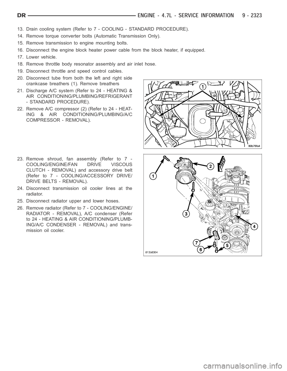
20. Disconnect tube from both the left and right side
crankcase breathers (1). Remove breathers
21. Discharge A/C system (Refer to 24 - HEATING &
AIR CONDITIONING/PLUMBING/REFRIGERANT
- STANDARD PROCEDURE).
22. Remove A/C compressor (2) (Refer to 24 - HEAT-
ING & AIR CONDITIONING/PLUMBING/A/C
COMPRESSOR - REMOVAL).
23. Remove shroud, fan assembly (Refer to 7 -
COOLING/ENGINE/FAN DRIVE VISCOUS
CLUTCH - REMOVAL) and accessory drive belt
(Refer to 7 - COOLING/ACCESSORY DRIVE/
DRIVE BELTS - REMOVAL).
24. Disconnect transmission oil cooler lines at the
radiator.
25. Disconnect radiator upper and lower hoses.
26. Remove radiator (Refer to 7 - COOLING/ENGINE/
RADIATOR - REMOVAL), A/C condenser (Refer
to 24 - HEATING & AIR CONDITIONING/PLUMB-
ING/A/C CONDENSER - REMOVAL) and trans-
mission oil cooler.
Page 1638 of 5267
12. Position and install heater hoses (1) and tubes
onto intake manifold.
13. Install the heater hoses onto the heater core and
the engine front cover, and install clips (2).
14. Install generator (3) (Refer to 8 - ELECTRICAL/
CHARGING/GENERATOR - INSTALLATION).
15. Install A/C condenser (Refer to 24 - HEATING & AIR CONDITIONING/PLUMBING/A/C CONDENSER - INSTAL-
LATION), radiator (Refer to 7 - COOLING/ENGINE/RADIATOR - INSTALLATION)and transmission oil cooler.
16. Connect radiator upper and lower hoses.
17. Connect the transmission oil cooler lines to the radiator.
18. Install accessory drive belt (Refer to 7 - COOLING/ACCESSORY DRIVE/DRIVE BELTS - INSTALLATION), fan
assembly and shroud (Refer to 7 - COOLING/ENGINE/FAN DRIVE VISCOUS CLUTCH- INSTALLATION).
Page 1645 of 5267

OIL PRESSURE
SPECIFICATION SPECIFICATION
At Curb Idle Speed (MIN)* 48 kPa (7 psi)
@ 3000 rpm 240 - 725 kPa (35 - 105 psi)
* CAUTION: If pressure is zero at curb idle, DO NOT run engine at 3000 rpm.
TORQUE
DESCRIPTION Nꞏm Ft. In.
Lbs. Lbs.
Camshaft
Non - Oiled Sprocket Bolt 122 90 —
Bearing Cap Bolts 11 — 100
Timing Chain Cover—Bolts 58 43 —
Connecting Rod Cap—Bolts 27 20 —
PLUS 90° TURN
Bed Plate—Bolts Refer to Procedure
Cylinder Head—Bolts Refer to Procedure
Crankshaft Damper—Bolt 175 130 —
Cylinder Head Cover—Bolts 12 — 105
Exhaust Manifold—Bolts 25 18 —
Exhaust Manifold Heat Shield—Nuts 8 — 72
Then loosen 45°
Flexplate—Bolts 60 45 —
Engine Mount Bracket to Block—Bolts 61 45 —
Rear Mount to Transmission—Bolts 46 34 —
Generator Mounting—Bolts
M10 Bolts 54 40 —
M8 Bolts 28 — 250
Intake Manifold—Bolts 12 — 105
Refer to Procedure for
Tightening Sequence
Oil Pan—Bolts 15 — 130
Oil Pan—Drain Plug 34 25 —
Oil Pump—Bolts 28 — 250
Oil Pump Cover—Bolts 12 — 105
Oil Pickup Tube—Bolt and Nut 28 — 250
Oil Dipstick Tube to Engine
Block—Bolt 15 — 130
Oil Fill Tube—Bolts 12 — 105
Timing Chain Guide—Bolts 28 — 250
Timing Chain Tensioner Arm—Pin Bolt 17 — 150
Hydraulic Tensioner—Bolts 28 — 250
Timing Chain Primary Tensioner—Bolts 28 — 250
Page 1688 of 5267

ENGINE BLOCK
DESCRIPTION
The cylinder block is made of cast iron.The block is a closed deck design with the left bank forward. To provide
high rigidity and improved NVH an enhanced compacted graphite bedplate isbolted to the block. The block design
allows coolant flow between the cylinders bores, and an internal coolant bypass to a single poppet inlet thermostat
is included in the cast aluminum front cover.
STANDARD PROCEDURE - CYLINDER BORE HONING
Before honing, stuff plenty of clean shop towels under
the bores and over the crankshaft to keep abrasive
materials from entering the crankshaft area.
1. Used carefully, the Cylinder Bore Sizing Hone
C-823, equipped with 220 grit stones, is the best
tool for this job. In addition to deglazing, it will
reduce taper and out-of-round, as well as removing
light scuffing, scoring and scratches. Usually, a few
strokes will clean up a bore and maintain the
required limits.
CAUTION: DO NOT use rigid type hones to remove
cylinder wall glaze.
2. Deglazing of the cylinder walls may be done if the
cylinder bore is straight and round. Use a cylinder
surfacing hone, Honing Tool C-3501, equipped with
280 grit stones (C-3501-3810). about 20-60
strokes, depending on the bore condition, will be
sufficient to provide a satisfactory surface. Using
honing oil C-3501-3880, or a light honing oil, avail-
able from major oil distributors.
CAUTION: DO NOT use engine or transmission oil, mineral spirits, or kerosene.
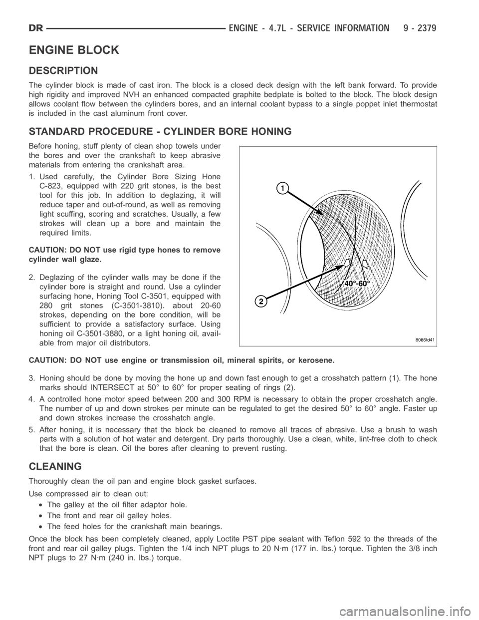
3. Honing should be done by moving the hone up and down fast enough to get a crosshatch pattern (1). The hone
marks should INTERSECT at 50° to 60° for proper seating of rings (2).
4. A controlled hone motor speed between 200 and 300 RPM is necessary to obtain the proper crosshatch angle.
The number of up and down strokes per minute can be regulated to get the desired 50° to 60° angle. Faster up
and down strokes increase the crosshatch angle.
5. After honing, it is necessary that the block be cleaned to remove all traces of abrasive. Use a brush to wash
parts with a solution of hot water and detergent. Dry parts thoroughly. Usea clean, white, lint-free cloth to check
that the bore is clean. Oil the bores after cleaning to prevent rusting.
CLEANING
Thoroughly clean the oil pan and engine block gasket surfaces.
Use compressed air to clean out:
The galley at the oil filter adaptor hole.
The front and rear oil galley holes.
The feed holes for the crankshaft main bearings.
Once the block has been completely cleaned, apply Loctite PST pipe sealantwith Teflon 592 to the threads of the
front and rear oil galley plugs. Tighten the 1/4 inch NPT plugs to 20 Nꞏm (177in. lbs.) torque. Tighten the 3/8 inch
NPT plugs to 27 Nꞏm (240 in. lbs.) torque.
Page 1700 of 5267
SEAL - CRANKSHAFT OIL - FRONT
REMOVAL
1. Disconnect negative cable from battery.
2. Remove accessory drive belt (Refer to 7 - COOL-
ING/ACCESSORY DRIVE/DRIVE BELTS -
REMOVAL).
3. Remove A/C compressor mouning fasteners and
set aside.
4. Drain cooling system (Refer to 7 - COOLING -
STANDARD PROCEDURE).
5. Remove upper radiator hose.
6. Disconnect electrical connector for fan mounted
inside radiator shroud.
7. Remove radiator shroud attaching fasteners.
NOTE: Transmission cooler line snaps into shroud
lower right hand corner.
8. Remove radiator cooling fan and shroud (Refer to
7 - COOLING/ENGINE/RADIATOR FAN -
REMOVAL).
9. Remove crankshaft damper bolt.
10. Remove damper using Special Tools 8513 Insert
and 1026 Three Jaw Puller (2).
11. Using Special Tool 8511 (1), remove crankshaft
front seal.
Page 1703 of 5267
INSTALLATION
1. Lubricate the crankshaft flange with engine oil.
2. Position the magnetic seal guide Special Tool
8349-2 onto the crankshaft rear face. Then position
the crankshaft rear oil seal (1) onto the guide (2).
3. Using Special Tools 8349 Crankshaft Rear Oil Seal
Installer (2) and C-4171 Driver Handle (3), with a
hammer, tap the seal (1) into place. Continue to
tap on the driver handle until the seal installer
seats against the cylinder block crankshaft bore.
4. Install the flexplate.
5. Install the transmission.
Page 1768 of 5267
11. Remove generator assembly (2) (Refer to 8 -
ELECTRICAL/CHARGING/GENERATOR -
REMOVAL).
12. Remove the intake manifold and IAFM as an
assembly (Refer to 9 - ENGINE/MANIFOLDS/IN-
TAKE MANIFOLD - REMOVAL).
13. Disconnect the heater hoses.
NOTE: It is not necessary to disconnect P/S hoses
from pump, for P/S pump removal.
14. Remove the power steering pump and set aside.
15. Disconnect the fuel supply line (Refer to 14 -
FUEL SYSTEM/FUEL DELIVERY/QUICK CON-
NECT FITTING - STANDARD PROCEDURE).
16. Raise and support the vehicle on a hoist and
drain the engine oil.
17. Remove engine front mount thru-bolt nuts.
18. Remove right side axle retaining bolts.
19. Disconnect the transmission oil cooler lines from
their retainers at the oil pan bolts.
20. Disconnect exhaust pipe at manifolds (2).
Page 1775 of 5267
21. Install the accessory drive belt (Refer to 7 -
COOLING/ACCESSORY DRIVE/DRIVE BELTS -
INSTALLATION).
22. Install upper radiator support crossmember.
23. Install radiator (1) (Refer to 7 - COOLING/EN-
GINE/RADIATOR - INSTALLATION).
24. Connect the radiator lower hose.
25. Connect the transmission oil cooler lines to the
radiator.