2006 DODGE RAM SRT-10 transmission oil
[x] Cancel search: transmission oilPage 2031 of 5267
STANDARD PROCEDURE
ENGINE CORE AND OIL GALLERY PLUGS
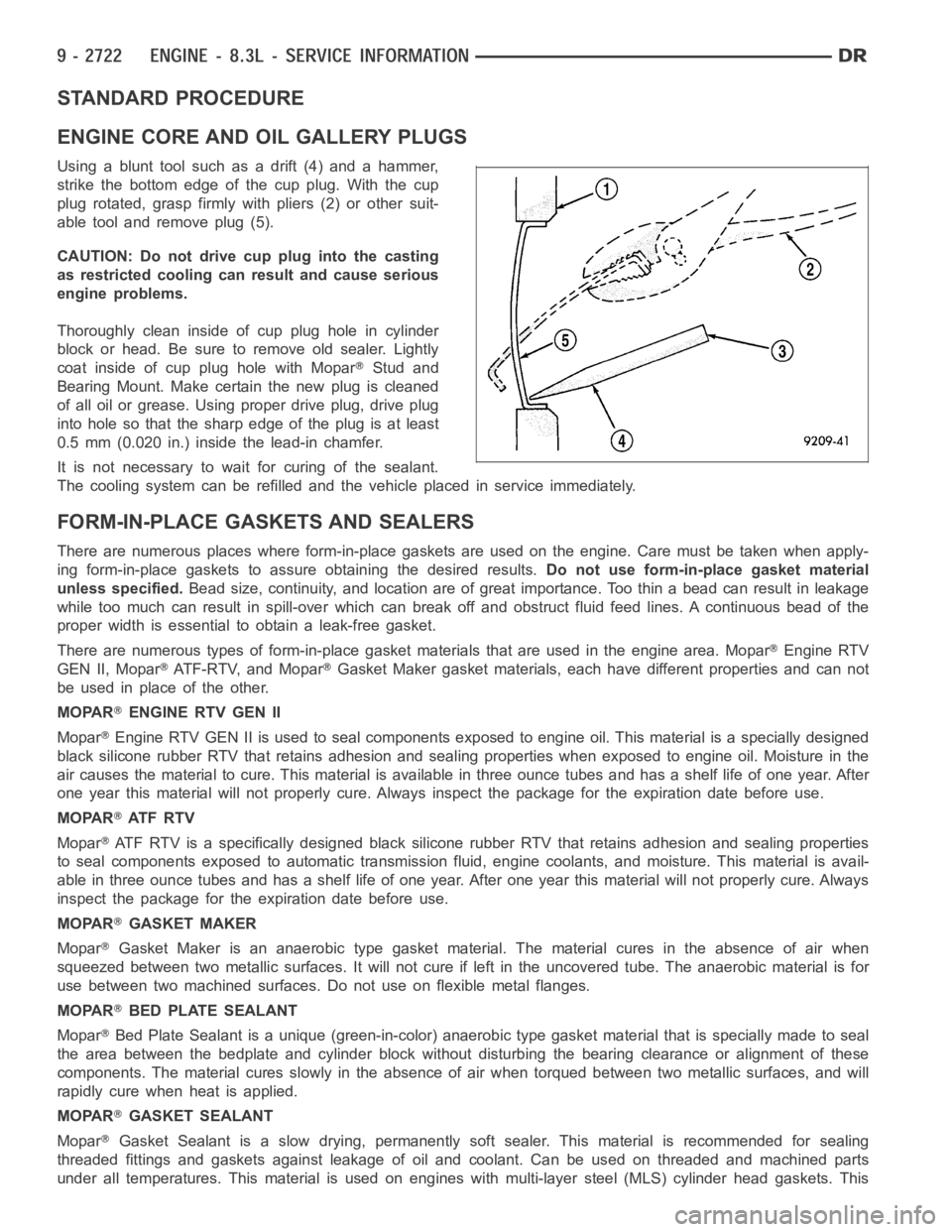
Using a blunt tool such as a drift (4) and a hammer,
strike the bottom edge of the cup plug. With the cup
plug rotated, grasp firmly with pliers (2) or other suit-
able tool and remove plug (5).
CAUTION: Do not drive cup plug into the casting
as restricted cooling can result and cause serious
engine problems.
Thoroughly clean inside of cup plug hole in cylinder
block or head. Be sure to remove old sealer. Lightly
coat inside of cup plug hole with Mopar
Stud and
Bearing Mount. Make certain the new plug is cleaned
of all oil or grease. Using proper drive plug, drive plug
into hole so that the sharp edge of the plug is at least
0.5 mm (0.020 in.) inside the lead-in chamfer.
It is not necessary to wait for curing of the sealant.
The cooling system can be refilled and the vehicle placed in service immediately.
FORM-IN-PLACE GASKETS AND SEALERS
There are numerous places where form-in-place gaskets are used on the engine. Care must be taken when apply-
ing form-in-place gaskets to assure obtaining the desired results.Do not use form-in-place gasket material
unless specified.Bead size, continuity, and location are of great importance. Too thin a bead can result in leakage
while too much can result in spill-overwhich can break off and obstruct fluid feed lines. A continuous bead of the
proper width is essential to obtain a leak-free gasket.
There are numerous types of form-in-place gasket materials that are used in the engine area. Mopar
Engine RTV
GEN II, Mopar
ATF-RTV, and MoparGasket Maker gasket materials, each have different properties and can not
be used in place of the other.
MOPAR
ENGINE RTV GEN II
Mopar
Engine RTV GEN II is used to seal components exposed to engine oil. This material is a specially designed
black silicone rubber RTV that retains adhesion and sealing properties when exposed to engine oil. Moisture in the
air causes the material to cure. This material is available in three ounce tubes and has a shelf life of one year. After
one year this material will not properly cure. Always inspect the package for the expiration date before use.
MOPAR
AT F R T V
Mopar
ATF RTV is a specifically designed black silicone rubber RTV that retains adhesion and sealing properties
to seal components exposed to automatic transmission fluid, engine coolants, and moisture. This material is avail-
able in three ounce tubes and has a shelf life of one year. After one year thismaterial will not properly cure. Always
inspect the package for the expiration date before use.
MOPAR
GASKET MAKER
Mopar
Gasket Maker is an anaerobic type gasket material. The material cures in the absence of air when
squeezed between two metallic surfaces. It will not cure if left in the uncovered tube. The anaerobic material is for
use between two machined surfaces. Do not use on flexible metal flanges.
MOPAR
BED PLATE SEALANT
Mopar
Bed Plate Sealant is a unique (green-in-color) anaerobic type gasket material that is specially made to seal
the area between the bedplate and cylinder block without disturbing the bearing clearance or alignment of these
components. The material cures slowly in the absence of air when torqued between two metallic surfaces, and will
rapidly cure when heat is applied.
MOPAR
GASKET SEALANT
Mopar
Gasket Sealant is a slow drying, permanently soft sealer. This material isrecommended for sealing
threaded fittings and gaskets against leakage of oil and coolant. Can be used on threaded and machined parts
under all temperatures. This material is used on engines with multi-layersteel (MLS) cylinder head gaskets. This
Page 2033 of 5267
5. Identify the fluid in the cylinder(s) (i.e., coolant, fuel, oil or other).
6. Make sure all fluid has been removed from the cylinders. Inspect engine for damage (i.e., connecting rods, pis-
tons, valves, etc.)
7. Repair engine or components as necessary to prevent this problem from re-occurring.
CAUTION: Squirt approximately one teaspoon of oil into the cylinders, rotateenginetolubricatethecylin-
der walls to prevent damage on restart.
8. Install new spark plugs.
9. Drain engine oil and remove oil filter.
10. Fill engine with specified amount of approved oil and install new oil filter.
11. Connect negative battery cable.
12. Start engine and check for any leaks.
REMOVAL - ENGINE ASSEMBLY
1. Perform fuel pressure release procedure (Refer to
14 - FUEL SYSTEM/FUEL DELIVERY - STAN-
DARD PROCEDURE).
2. Disconnect negative battery cable.
3. Disconnect throttle body air inlet duct, remove air
cleaner cover (Refer to 9 - ENGINE/AIR INTAKE
SYSTEM/AIR CLEANER ELEMENT - REMOVAL).
4. Raise and support the vehicle.
5. Remove the lower engine shield.
6. Drain cooling system (Refer to 7 - COOLING/EN-
GINE - STANDARD PROCEDURE - DRAINING
COOLING SYSTEM).
7. Paint mark and remove the driveshaft (Refer to 3 -
DIFFERENTIAL & DRIVELINE/PROPELLER
SHAFT/PROPELLER SHAFT - REMOVAL).
8.Removethetransmission(Referto21-TRANS-
MISSION/TRANSAXLE/MANUAL - REMOVAL).
9. Remove the starter (Refer to 8 - ELECTRICAL/
STARTING/STARTER MOTOR - REMOVAL).
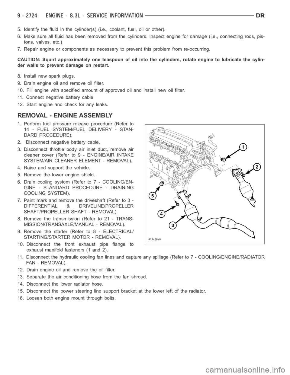
10. Disconnect the front exhaust pipe flange to
exhaust manifold fasteners (1 and 2).
11. Disconnect the hydraulic cooling fan lines and capture any spillage (Refer to 7 - COOLING/ENGINE/RADIATOR
FA N - R E M O VA L ) .
12. Drain engine oil and remove the oil filter.
13. Separate the air conditioning hose from the fan shroud.
14. Disconnect the lower radiator hose.
15. Disconnect the power steering line support bracket at the lower left ofthe radiator.
16. Loosen both engine mount through bolts.
Page 2038 of 5267
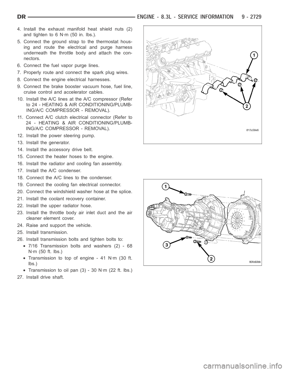
4. Install the exhaust manifold heat shield nuts (2)
and tighten to 6 Nꞏm (50 in. lbs.).
5. Connect the ground strap to the thermostat hous-
ing and route the electrical and purge harness
underneath the throttle body and attach the con-
nectors.
6. Connect the fuel vapor purge lines.
7. Properly route and connect the spark plug wires.
8. Connect the engine electrical harnesses.
9. Connect the brake booster vacuum hose, fuel line,
cruise control and accelerator cables.
10. Install the A/C lines at the A/C compressor (Refer
to 24 - HEATING & AIR CONDITIONING/PLUMB-
ING/A/C COMPRESSOR - REMOVAL).
11. Connect A/C clutch electrical connector (Refer to
24 - HEATING & AIR CONDITIONING/PLUMB-
ING/A/C COMPRESSOR - REMOVAL).
12. Install the power steering pump.
13. Install the generator.
14. Install the accessory drive belt.
15. Connect the heater hoses to the engine.
16. Install the radiator and cooling fan assembly.
17. Install the A/C condenser.
18. Connect the A/C lines to the condenser.
19. Connect the cooling fan electrical connector.
20. Connect the windshield washer hose at the splice.
21. Install the coolant recovery container.
22. Install the upper radiator hose.
23. Install the throttle body air inlet duct and the air
cleaner element cover.
24. Raise and support the vehicle.
25. Install transmission.
26. Install transmission bolts and tighten bolts to:
7/16 Transmission bolts and washers (2) - 68
Nꞏm (50 ft. lbs.)
Transmission to top of engine - 41 Nꞏm (30 ft.
lbs.)
Transmission to oil pan (3) - 30 Nꞏm (22 ft. lbs.)
27. Install drive shaft.
Page 2094 of 5267
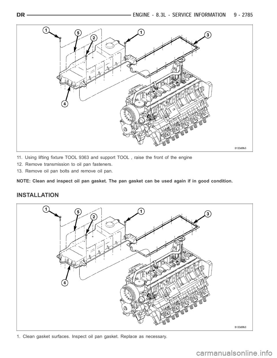
11. Using lifting fixture TOOL 9363 and support TOOL , raise the front of theengine
12. Remove transmission to oil pan fasteners.
13. Remove oil pan bolts and remove oil pan.
NOTE: Clean and inspect oil pan gasket. The pan gasket can be used again if ingood condition.
INSTALLATION
1. Clean gasket surfaces.Inspect oil pan gasket. Replace as necessary.
Page 2095 of 5267
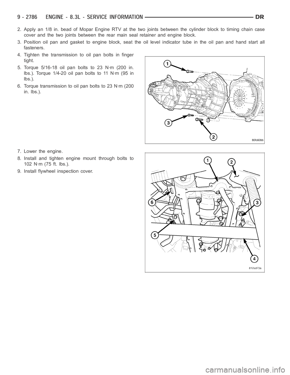
2. Apply an 1/8 in. bead of Mopar Engine RTV at the two joints between the cylinder block to timing chain case
cover and the two joints between the rear main seal retainer and engine block.
3. Position oil pan and gasket to engine block, seat the oil level indicatortube in the oil pan and hand start all
fasteners.
4. Tighten the transmission to oil pan bolts in finger
tight.
5. Torque 5/16-18 oil pan bolts to 23 Nꞏm (200 in.
lbs.). Torque 1/4-20 oil pan bolts to 11 Nꞏm (95 in
lbs.).
6. Torque transmission to oil pan bolts to 23 Nꞏm (200
in. lbs.).
7. Lower the engine.
8. Install and tighten engine mount through bolts to
102 Nꞏm (75 ft. lbs.).
9. Install flywheel inspection cover.
Page 2104 of 5267
BLOCK-ENGINE
DESCRIPTION
The cylinder block is made of a sand-cast aluminum alloy. The cylinder block has interference-fit cast iron cylinder
liners. The cylinder liners are thermally installed during block manufacturing; they are not serviceable items.
Six iron main bearing caps use four bolts per cap; two vertical and two horizontal. A crankshaft oil scraper is
attached to the main bearing caps via extended main bearing cap bolts and nuts.
STANDARD PROCEDURE - CYLINDER BORE HONING
Before honing, stuff plenty of clean shop towels under
the bores and over the crankshaft to keep abrasive
materials from entering the crankshaft area.
1. Used carefully, the Cylinder Bore Sizing Hone
C-823, equipped with 220 grit stones, is the best
tool for this job. In addition to deglazing, it will
reduce taper and out-of-round, as well as removing
light scuffing, scoring and scratches. Usually, a few
strokes will clean up a bore and maintain the
required limits.
CAUTION: DO NOT use rigid type hones to remove
cylinder wall glaze.
2. Deglazing of the cylinder walls may be done if the
cylinder bore is straight and round. Use a cylinder
surfacing hone, Honing Tool C-3501, equipped with
280 grit stones (C-3501-3810). about 20-60
strokes, depending on the bore condition, will be
sufficient to provide a satisfactory surface. Using
honing oil C-3501-3880, or a light honing oil, avail-
able from major oil distributors.
CAUTION: DO NOT use engine or transmission oil, mineral spirits, or kerosene.
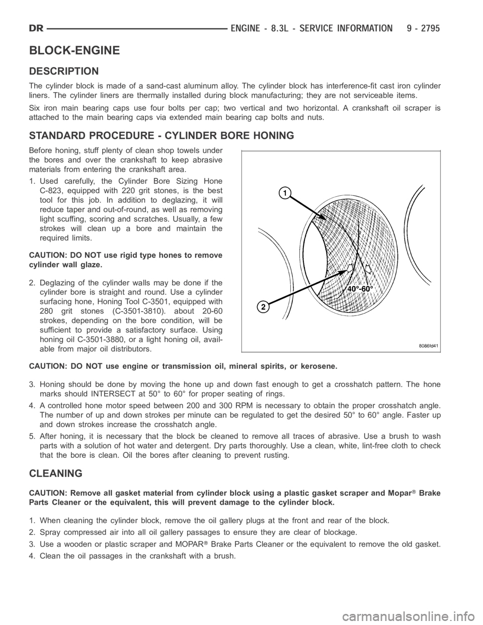
3. Honing should be done by moving the hone up and down fast enough to get a crosshatch pattern. The hone
marks should INTERSECT at 50° to 60° for proper seating of rings.
4. A controlled hone motor speed between 200 and 300 RPM is necessary to obtain the proper crosshatch angle.
The number of up and down strokes per minute can be regulated to get the desired 50° to 60° angle. Faster up
and down strokes increase the crosshatch angle.
5. After honing, it is necessary that the block be cleaned to remove all traces of abrasive. Use a brush to wash
parts with a solution of hot water and detergent. Dry parts thoroughly. Usea clean, white, lint-free cloth to check
that the bore is clean. Oil the bores after cleaning to prevent rusting.
CLEANING
CAUTION: Remove all gasket material from cylinder block using a plastic gasket scraper and MoparBrake
Parts Cleaner or the equivalent, this will prevent damage to the cylinder block.
1. When cleaning the cylinder block, remove the oil gallery plugs at the front and rear of the block.
2. Spray compressed air into all oil gallery passages to ensure they are clear of blockage.
3. Use a wooden or plastic scraper and MOPAR
Brake Parts Cleaner or the equivalent to remove the old gasket.
4. Clean the oil passages in the crankshaft with a brush.
Page 2124 of 5267
SEAL-OIL-REAR-CRANK AND RETAINER
REMOVAL
1. Remove transmission (Refer to 21 - TRANSMIS-
SION/TRANSAXLE/MANUAL - REMOVAL).
2. Remove clutch and flywheel (Refer to 6 - CLUTCH/
CLUTCH DISC - REMOVAL).
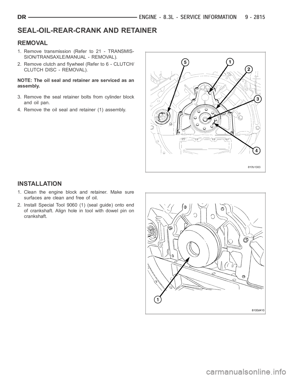
NOTE: The oil seal and retainer are serviced as an
assembly.
3. Remove the seal retainer bolts from cylinder block
and oil pan.
4. Remove the oil seal and retainer (1) assembly.
INSTALLATION
1. Clean the engine block and retainer. Make sure
surfaces are clean and free of oil.
2. Install Special Tool 9060 (1) (seal guide) onto end
of crankshaft. Align hole in tool with dowel pin on
crankshaft.
Page 2125 of 5267
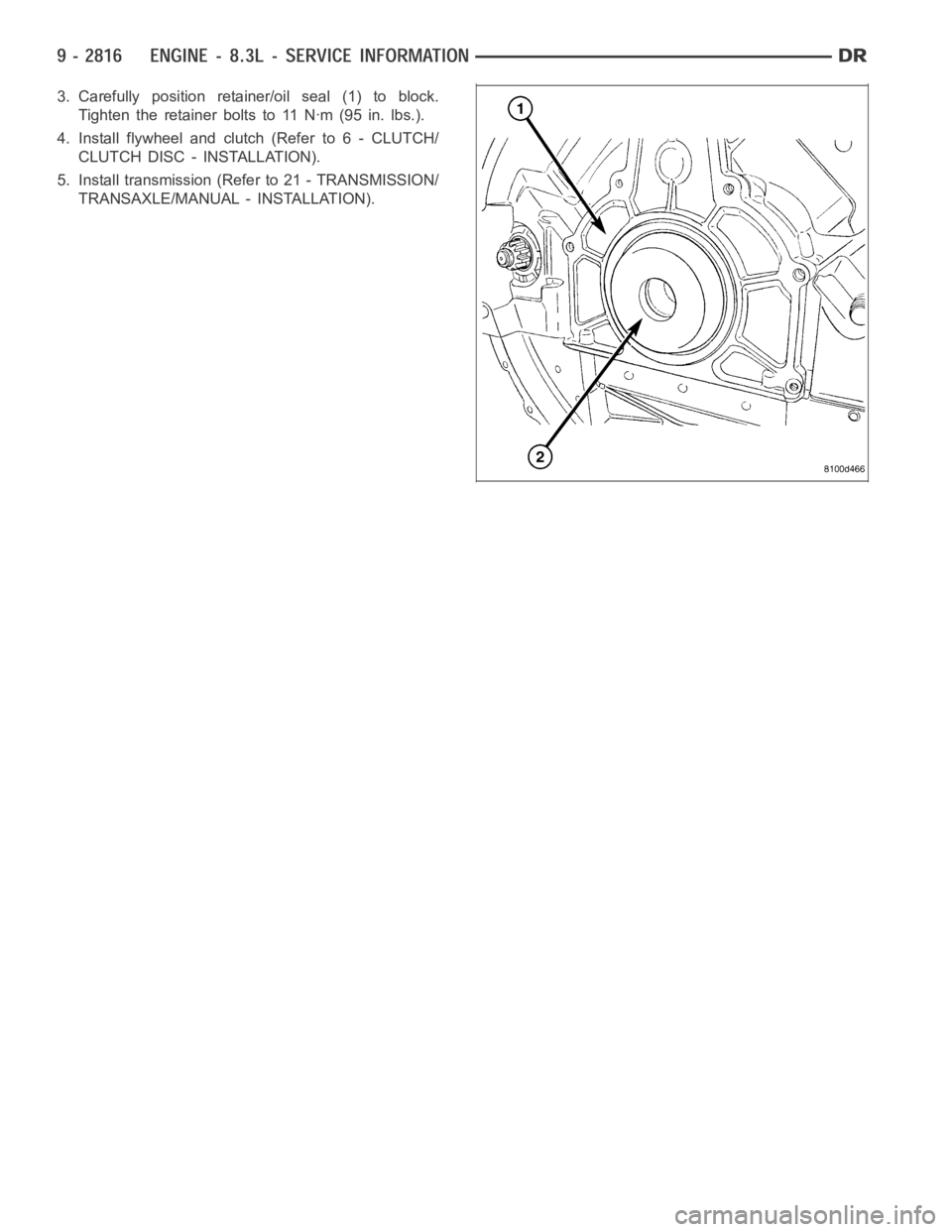
3. Carefully position retainer/oil seal (1) to block.
Tighten the retainer bolts to 11 Nꞏm (95 in. lbs.).
4. Install flywheel and clutch (Refer to 6 - CLUTCH/
CLUTCH DISC - INSTALLATION).
5. Install transmission (Refer to 21 - TRANSMISSION/
TRANSAXLE/MANUAL - INSTALLATION).