2006 DODGE RAM SRT-10 wheel bolt torque
[x] Cancel search: wheel bolt torquePage 2242 of 5267

8. Connect other end of jumper wire to positive side of battery.
9. Connect one end of a second jumper wire to remaining injector terminal.
CAUTION: Powering an injector for more than a few seconds will permanentlydamage the injector.
10. Momentarily touch other end of jumper wire to negative terminal of battery for no more than a few seconds.
11. Place a rag or towel below fuel line quick-connect fitting at fuel rail.
12. Disconnect quick-connect fitting at fuel rail. Refer to Quick-Connect Fittings.
13. Return fuel pump relay to PDC.
14. One or more Diagnostic Trouble Codes (DTC’s) may have been stored in PCMmemory due to fuel pump relay
removal. The DRB
scantoolmustbeusedtoeraseaDTC.
STANDARD PROCEDURE - DRAINING FUEL TANK - EXCEPT DIESEL
WARNING: The fuel system may be under constant fuel pressure even with the engine off. This pressure
must be released before servicing fuel tank.
Two different procedures may be used to drain fuel tank: through the fuel fill fitting on tank, or using a diagnostic
scan tool to activate the fuel pump relay. Due to a one-way check valve installed into the fuel fill opening fitting at
the tank, the tank cannot be drained conventionally at the fill cap.
The quickest draining procedure involves removing the rubber fuel fill hose at the fuel tank.
As an alternative procedure, the electric fuel pump may be activated allowingtanktobedrainedatfuelrailcon-
nection. Refer to diagnostic scan tool for fuel pump activation procedures. Before disconnecting fuel line at fuel rail,
release fuel pressure. Refer to the Fuel System Pressure Release Procedure for procedures. Attach end of special
test hose tool number 6631 or 6539 at fuel rail disconnection (tool number 6631isusedon5/16”fuellineswhile
tool number 6539 is used on 3/8” fuel lines). Position opposite end of this hose tool to an approved gasoline drain-
ing station. Activate fuel pump and drain tank until empty.
If electric fuel pump is not operating, fuel must be drained through fuel fill fitting at tank. Refer to following proce-
dures.
1. Release fuel system pressure.
2. Raise vehicle.
3. Thoroughly clean area around fuel fill fitting and rubber fuel fill hoseat tank.
4. If vehicle is equipped with 4 doors and a 6 foot (short) box, remove left-rear tire/wheel.
5. Loosen clamp and disconnect rubber fuel fill hose at tank fitting. Usingan approved gas holding tank, drain fuel
tank through this fitting.
SPECIFICATIONS
FUEL SYSTEM PRESSURE
58 psi +/- 2 psi
TORQUE - EXCEPT DIESEL
DESCRIPTION N-m Ft. Lbs. In. Lbs.
Accelerator Pedal Bracket
Mounting12 - 105
Accelerator Pedal Position
Sensor Bracket-to-Battery
Tray Bolts3-30
Crankshaft Position
Sensor - 3.7L28 21 -
Crankshaft Position
Sensor - 4.7L28 21 -
Page 2344 of 5267
WARNING: The fuel injection pump supplies extremely high fuel pressure toeach individual injector
through the high-pressure lines. Fuel under this amount of pressure can penetrate the skin and cause per-
sonal injury. Wear safety goggles and adequate protective clothing. Do not loosen fuel fittings while engine
is running.
WARNING: Engine may start while cranking starter motor.
DRAINING FUEL TANK - DIESEL
Due to a one-way check valve installed into the fuel fill opening fitting atthe tank, the tank cannot be drained con-
ventionally at the fill cap.
1. Raise vehicle.
2. If vehicle is equipped with 4 doors and a 6 foot (short) box, remove left-rear tire/wheel.
3. Thoroughly clean area at top of fuel tank around fuel tank module.
4. Loosen clamp and disconnect rubber fuel fill hose at tank.
5. Drain fuel tank by attaching drain hose from an approved diesel fuel draining station to the fuel fill fitting of tank.
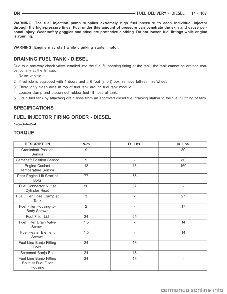
SPECIFICATIONS
FUEL INJECTOR FIRING ORDER - DIESEL
1–5–3–6–2–4
TORQUE
DESCRIPTION N-m Ft. Lbs. In. Lbs.
Crankshaft Position
Sensor980
Camshaft Position Sensor 9 - 80
Engine Coolant
Temperature Sensor18 13 160
Rear Engine Lift Bracket
Bolts77 56 -
Fuel Connector Nut at
Cylinder Head50 37 -
Fuel Filler Hose Clamp at
Ta n k3-27
Fuel Filler Housing-to-
Body Screws2-17
Fuel Filter Lid 34 25 -
Fuel Filter Drain Valve
Screws1.5 - 14
Fuel Heater Element
Screws1.5 - 14
Fuel Line Banjo Fitting
Bolts24 18 -
Screened Banjo Bolt 24 18 -
Fuel Line Banjo Fitting
Bolts at Fuel Filter
Housing24 18 -
Page 2414 of 5267
DESCRIPTION - SRT10
The SRT-10 column has noSTARTposition on the key cylinder. The push starter button switch is mounted on the
Instrument panel center stack. All SRT-10 columns are Tilt columns, Standard cab trucks come with manual trans-
missions, Quad cab trucks come equipped with automatic transmissions.
DIAGNOSIS AND TESTING
STEERING COLUMN
If the vehicle is involved in a front end collision/the air bag has deployedthe column must be inspected. This
inspection will determine if the Column has collapsed. Inspect the columnmounting capsules visually and manually
push and pull them to check for separation or fractures. If capsules are fractured or have moved the column MUST
be replaced.
REMOVAL
WARNING: Before servicing the steering column the airbag system must be disarmed. Refer to electrical
restraint system for service procedures. Failure to do so may result in accidental deployment of the airbag
and possible personal injury.
CAUTION: All fasteners must be torqued to specification to ensure proper operation of the steering column.
1. Position the front wheelsstraight ahead.
2. Disconnect the negative (ground) cable from the battery.
3. Remove the airbag, (Refer to 8 - ELECTRICAL/RE-
STRAINTS/DRIVER AIRBAG - REMOVAL).
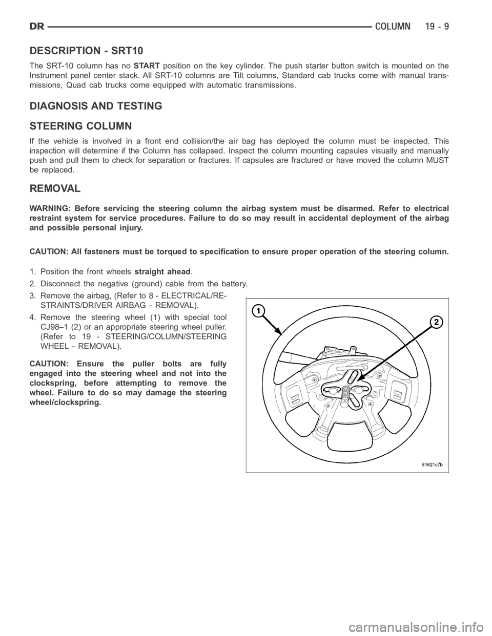
4. Remove the steering wheel (1) with special tool
CJ98–1 (2) or an appropriate steering wheel puller.
(Refer to 19 - STEERING/COLUMN/STEERING
WHEEL - REMOVAL).
CAUTION: Ensure the puller bolts are fully
engaged into the steering wheel and not into the
clockspring, before attempting to remove the
wheel. Failure to do so may damage the steering
wheel/clockspring.
Page 2419 of 5267
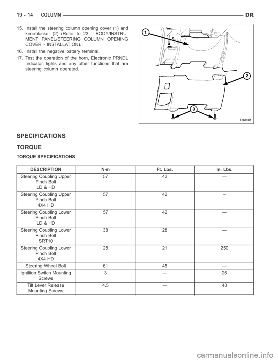
15. Install the steering column opening cover (1) and
kneeblocker (2) (Refer to 23 - BODY/INSTRU-
MENT PANEL/STEERING COLUMN OPENING
COVER - INSTALLATION).
16. Install the negative battery terminal.
17. Test the operation of the horn, Electronic PRNDL
Indicator, lights and any other functions that are
steering column operated.
SPECIFICATIONS
TORQUE
TORQUE SPECIFICATIONS
DESCRIPTION Nꞏm Ft. Lbs. In. Lbs.
Steering Coupling Upper
Pinch Bolt
LD & HD57 42 —
Steering Coupling Upper
Pinch Bolt
4X4 HD57 42 –
Steering Coupling Lower
Pinch Bolt
LD & HD57 42 —
Steering Coupling Lower
Pinch Bolt
SRT1038 28 —
Steering Coupling Lower
Pinch Bolt
4X4 HD28 21 250
Steering Wheel Bolt 61 45 —
Ignitiion Switch Mounting
Screws3—26
Tilt Lever Release
Mounting Screws4.5 — 40
Page 2429 of 5267
STEERING WHEEL
REMOVAL
1. Disable and remove the driver’s side airbag. (Refer
to 8 - ELECTRICAL/RESTRAINTS/DRIVER AIR-
BAG - REMOVAL).
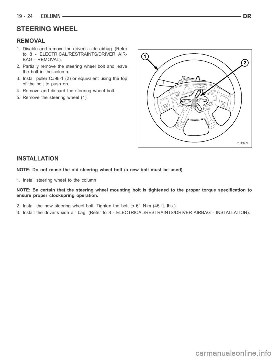
2. Partially remove the steering wheel bolt and leave
theboltinthecolumn.
3. Install puller CJ98-1 (2) or equivalent using the top
ofthebolttopushon.
4. Remove and discard the steering wheel bolt.
5. Remove the steering wheel (1).
INSTALLATION
NOTE: Do not reuse the old steering wheel bolt (a new bolt must be used)
1. Install steering wheel to the column
NOTE: Be certain that the steering wheel mounting bolt is tightened to the proper torque specification to
ensure proper clockspring operation.
2. Install the new steering wheel bolt. Tighten the bolt to 61 Nꞏm (45 ft. lbs.).
3. Install the driver’s side air bag. (Refer to 8 - ELECTRICAL/RESTRAINTS/DRIVER AIRBAG - INSTALLATION).
Page 2445 of 5267
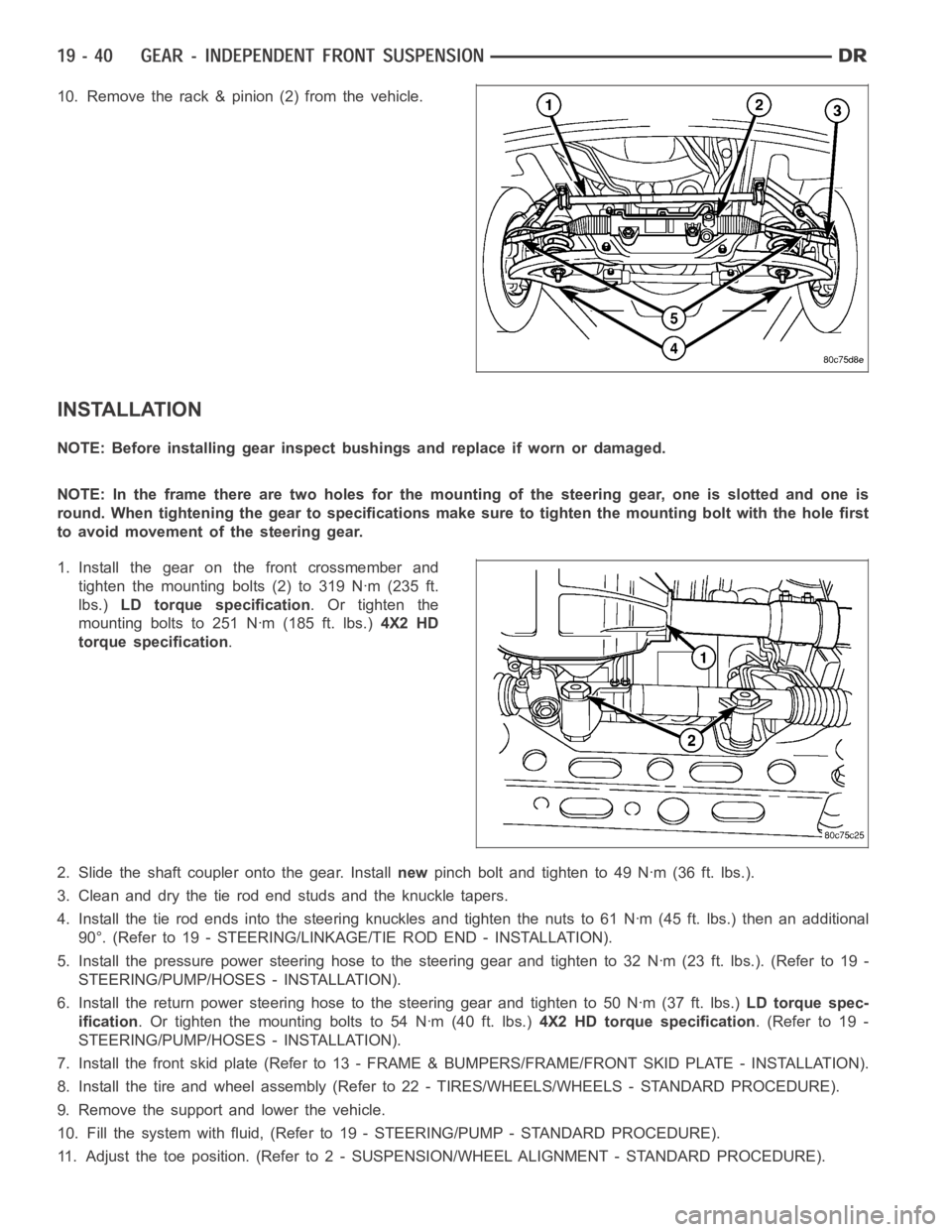
10. Remove the rack & pinion (2) from the vehicle.
INSTALLATION
NOTE: Before installing gear inspect bushings and replace if worn or damaged.
NOTE: In the frame there are two holes for the mounting of the steering gear,oneisslottedandoneis
round. When tightening the gear to specificationsmakesuretotightenthemounting bolt with the hole first
to avoid movement of the steering gear.
1. Install the gear on the front crossmember and
tighten the mounting bolts (2) to 319 Nꞏm (235 ft.
lbs.)LD torque specification.Ortightenthe
mounting bolts to 251 Nꞏm (185 ft. lbs.)4X2 HD
torque specification.
2. Slide the shaft coupler onto the gear. Installnewpinch bolt and tighten to 49 Nꞏm (36 ft. lbs.).
3. Clean and dry the tie rod end studs and the knuckle tapers.
4. Install the tie rod ends into the steering knuckles and tighten the nuts to61Nꞏm(45ft.lbs.)thenanadditional
90°. (Refer to 19 - STEERING/LINKAGE/TIE ROD END - INSTALLATION).
5. Install the pressure power steering hose to the steering gear and tightento32Nꞏm(23ft.lbs.).(Referto19-
STEERING/PUMP/HOSES - INSTALLATION).
6. Install the return power steering hose to the steering gear and tighten to50Nꞏm(37ft.lbs.)LD torque spec-
ification. Or tighten the mounting bolts to 54 Nꞏm (40 ft. lbs.)4X2 HD torque specification.(Referto19-
STEERING/PUMP/HOSES - INSTALLATION).
7. Install the front skid plate (Refer to 13 - FRAME & BUMPERS/FRAME/FRONT SKID PLATE - INSTALLATION).
8. Install the tire and wheel assembly (Refer to 22 - TIRES/WHEELS/WHEELS -STANDARD PROCEDURE).
9. Remove the support and lower the vehicle.
10. Fill the system with fluid, (Refer to 19 - STEERING/PUMP - STANDARD PROCEDURE).
11. Adjust the toe position. (Refer to 2 - SUSPENSION/WHEEL ALIGNMENT - STANDARD PROCEDURE).
Page 2451 of 5267
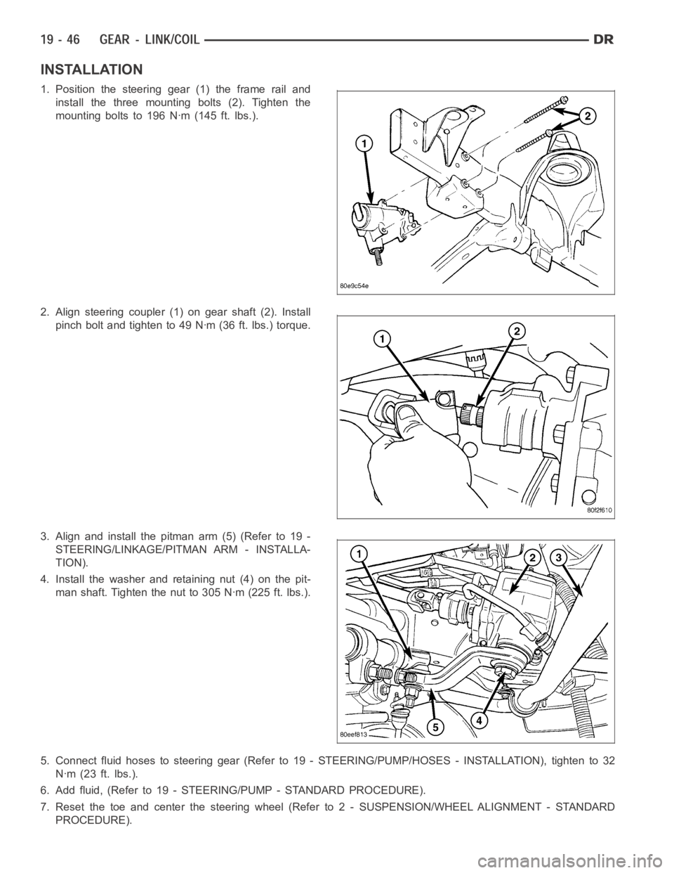
INSTALLATION
1. Position the steering gear (1) the frame rail and
install the three mounting bolts (2). Tighten the
mounting bolts to 196 Nꞏm (145 ft. lbs.).
2. Align steering coupler (1) on gear shaft (2). Install
pinch bolt and tighten to 49 Nꞏm (36 ft. lbs.) torque.
3. Align and install the pitman arm (5) (Refer to 19 -
STEERING/LINKAGE/PITMAN ARM - INSTALLA-
TION).
4. Install the washer and retaining nut (4) on the pit-
man shaft. Tighten the nut to 305 Nꞏm (225 ft. lbs.).
5. Connect fluid hoses to steering gear (Refer to 19 - STEERING/PUMP/HOSES- INSTALLATION), tighten to 32
Nꞏm (23 ft. lbs.).
6. Add fluid, (Refer to 19 - STEERING/PUMP - STANDARD PROCEDURE).
7. Reset the toe and center the steering wheel (Refer to 2 - SUSPENSION/WHEELALIGNMENT - STANDARD
PROCEDURE).
Page 2713 of 5267
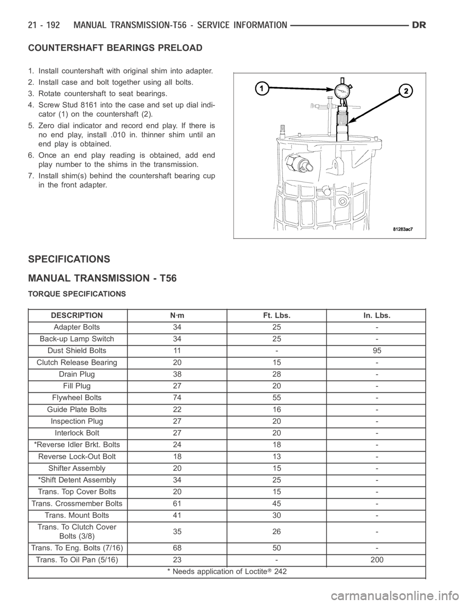
COUNTERSHAFT BEARINGS PRELOAD
1. Install countershaft with original shim into adapter.
2. Install case and bolt together using all bolts.
3. Rotate countershaft to seat bearings.
4. Screw Stud 8161 into the case and set up dial indi-
cator (1) on the countershaft (2).
5. Zero dial indicator and record end play. If there is
no end play, install .010 in. thinner shim until an
end play is obtained.
6. Once an end play reading is obtained, add end
play number to the shims in the transmission.
7. Install shim(s) behind the countershaft bearing cup
in the front adapter.
SPECIFICATIONS
MANUAL TRANSMISSION - T56
TORQUE SPECIFICATIONS
DESCRIPTION Nꞏm Ft. Lbs. In. Lbs.
Adapter Bolts 34 25 -
Back-up Lamp Switch 34 25 -
Dust Shield Bolts 11 - 95
Clutch Release Bearing 20 15 -
Drain Plug 38 28 -
Fill Plug 27 20 -
Flywheel Bolts 74 55 -
Guide Plate Bolts 22 16 -
Inspection Plug 27 20 -
Interlock Bolt 27 20 -
*Reverse Idler Brkt. Bolts 24 18 -
Reverse Lock-Out Bolt 18 13 -
Shifter Assembly 20 15 -
*Shift Detent Assembly 34 25 -
Trans. Top Cover Bolts 20 15 -
Trans. Crossmember Bolts 61 45 -
Trans. Mount Bolts 41 30 -
Trans. To Clutch Cover
Bolts (3/8)35 26 -
Trans. To Eng. Bolts (7/16) 68 50 -
Trans. To Oil Pan (5/16) 23 - 200
* Needs application of Loctite
242