Page 2320 of 5267
An O-ring (2) seals the sensor to the intake manifold.
1. Clean MAP sensor mounting hole at intake mani-
fold.
2. Check MAP sensor O-ring seal for cuts or tears.
3. Position sensor into manifold.
4. Install MAP sensor mounting bolts (screws). (Refer
to 14 - FUEL SYSTEM/FUEL DELIVERY - SPECI-
FICATIONS)
5. Connect electrical connector.
5.7L V-8
The Manifold Absolute Pressure (MAP) sensor (1) is
mounted to the front of the intake manifold air plenum
box.
1. Clean MAP sensor mounting hole at intake mani-
fold.
2. Check MAP sensor O-ring seal for cuts or tears.
3. Position sensor into manifold.
4. Rotate sensor 1/4 turn clockwise for installation.
5. Connect electrical connector.
8.3L - SRT-10
1. Install the MAP sensor to the intake manifold.
2. Install MAP sensor mounting screws and tighten mounting screws to 4 Nꞏm (35 in. lbs.).
3. Connect the electrical connector to the MAP sensor.
Page 2358 of 5267

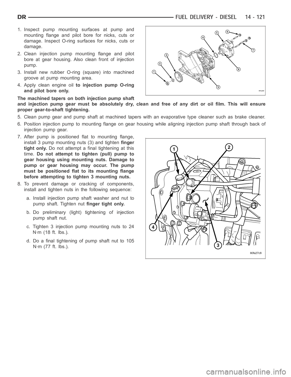
1. Inspect pump mounting surfaces at pump and
mounting flange and pilot bore for nicks, cuts or
damage. Inspect O-ring surfaces for nicks, cuts or
damage.
2. Clean injection pump mounting flange and pilot
bore at gear housing. Also clean front of injection
pump.
3. Install new rubber O-ring (square) into machined
groove at pump mounting area.
4. Apply clean engine oilto injection pump O-ring
and pilot bore only.
The machined tapers on both injection pump shaft
and injection pump gear must be absolutely dry, clean and free of any dirt oroil film. This will ensure
proper gear-to-shaft tightening.
5. Clean pump gear and pump shaft at machined tapers with an evaporative type cleaner such as brake cleaner.
6. Position injection pump to mounting flange on gear housing while aligning injection pump shaft through back of
injection pump gear.
7. After pump is positioned flat to mounting flange,
install 3 pump mounting nuts (3) and tightenfinger
tight only.Do not attempt a final tightening at this
time.Do not attempt to tighten (pull) pump to
gear housing using mounting nuts. Damage to
pump or gear housing may occur. The pump
must be positioned flat to its mounting flange
before attempting to tighten 3 mounting nuts.
8. To prevent damage or cracking of components,
install and tighten nuts in the following sequence:
a. Install injection pump shaft washer and nut to
pump shaft. Tighten nutfinger tight only.
b. Do preliminary (light) tightening of injection
pump shaft nut.
c. Tighten 3 injection pump mounting nuts to 24
Nꞏm (18 ft. lbs.).
d. Do a final tightening of pump shaft nut to 105
Nꞏm (77 ft. lbs.).
Page 2422 of 5267
7. Disconnect the electrical connector at rear of igni-
tion switch (4).
8. Remove ignition switch mounting screws (2).
9. Using a small screwdriver, push on locking tab (3)
and remove switch (1) from steering column.
INSTALLATION
The ignition key must be in the key cylinder for cylinder installation. Thekey cylinder must be removed first before
installing ignition switch.
1. Before installing ignitionswitch (1), rotate the slot
in the switch to the ON position.
2. Position switch (1) to column and install the mount-
ing screws (2). Tighten screw to 3 Nꞏm (26 in. lbs.).
3. Connect the electrical connector to rear of the igni-
tion switch (4). Make sure that locking tabs are fully
seated into wiring connector.
Page 2426 of 5267
INSTALLATION - SRT10
1. Ensure the ignition switch is in the RUN position
and the actuator shaft (2) in the lock housing (1) is
in the RUN position.
2. Carefully install the ignition switch. The switch will
snap over the retaining tabs. Install mounting
screw.
3. Install electrical connectors to ignition switch.
4. Install the multi-function switch and tighten the 2
screws.
5. Install upper and lower shrouds.
6. Install key cylinder (cylinder retaining tab will depress only in the RUN position).
7. Connect negative cable to battery.
8. Check for proper operation of ignition switch and key-in warning switch.
Page 2724 of 5267

page page
AUTOMATIC TRANSMISSION 42RLE -
ELECTRICAL DIAGNOSTICS
DIAGNOSIS AND TESTING
P0122-TPS/APP CIRCUIT LOW............. 205
P0123-TPS/APP CIRCUIT HIGH............. 207
P0124-TPS/APP INTERMITTENT ............ 209
P0218-HIGH TEMPERATURE OPERATION
A C T I VAT E D................................ 211
P0562-BATTERY VOLTAGE LOW ............ 213
P0602-CONTROL MODULE PROGRAMMING
ERROR/NOT PROGRAMMED............... 217
P0604-INTERNAL CONTROL MODULE RAM . 218
P0605-INTERNAL CONTROL MODULE ROM . 219
P0613-INTERNAL TRANSMISSION
PROCESSOR.............................. 220
P0706-TRANSMISSION RANGE SENSOR
RATIONALITY............................. 221
P0711-TRANSMISSION TEMPERATURE
SENSOR PERFORMANCE.................. 225
P0712-TRANSMISSION TEMPERATURE
SENSOR LOW............................. 228
P0713-TRANSMISSION TEMPERATURE
SENSOR HIGH............................ 231
P0714-TRANSMISSION TEMPERATURE
SENSOR INTERMITTENT................... 235
P0715-INPUT SPEED SENSOR 1 CIRCUIT . . . 238
P0720-OUTPUT SPEED SENSOR CIRCUIT . . 243
P0725-ENGINE SPEED SENSOR CIRCUIT . . . 248
P0731-GEAR RATIO ERROR IN 1ST ......... 250
P0732-GEAR RATIO ERROR IN 2ND ........ 252
P0733-GEAR RATIO ERROR IN 3RD ........ 254
P0734-GEAR RATIO ERROR IN 4TH ........ 256
P0736-GEAR RATIO ERROR IN REVERSE . . . 258
P0740-TCC OUT OF RANGE ................ 260
P0750-LR SOLENOID CIRCUIT............. 262
P0755-2/4 SOLENOID CIRCUIT ............. 266
P0760-OD SOLENOID CIRCUIT ............. 270
P0765-UD SOLENOID CIRCUIT ............. 274
P0841-LR PRESSURE SWITCH
RATIONALITY............................. 279
P0845-2/4 HYDRAULIC PRESSURE TEST . . . 284
P0846-2/4 PRESSURE SWITCH
RATIONALITY............................. 289
P0868-LINE PRESSURE LOW .............. 294
P0869-LINE PRESSURE HIGH .............. 300
P0870-OD HYDRAULIC PRESSURE TEST . . . 306P0871-OD PRESSURE SWITCH
RATIONALITY.............................. 311
P0882-TCM POWER INPUT LOW ........... 316
P0883-TCM POWER INPUT HIGH ........... 320
P0884-POWER UPAT SPEED .............. 324
P0890-SWITCHED BATTERY ............... 325
P0897-TRANSMISSION FLUID
DETERIORATED........................... 329
P0932-LINE PRESSURE SENSOR CIRCUIT . . 330
P0934-LINE PRESSURE SENSOR CIRCUIT
LOW...................................... 333
P0935-LINE PRESSURE SENSOR CIRCUIT
HIGH..................................... 338
P0944-LOSS OF HYDRAULIC PUMP PRIME . 343
P0992-2/4/OD HYDRAULIC PRESSURE
TEST..................................... 345
P128B-TCM POWER CONTROL CIRCUIT 2
LOW - TIPM............................... 346
P128C-TCM POWER CONTROL CIRCUIT 2
HIGH - TIPM............................... 349
P128D-TCM POWER CONTROL CIRCUIT 2
OPEN - TIPM.............................. 352
P128E-TCM POWER CONTROL CIRCUIT 2
OVERCURRENT - TIPM.................... 355
P1684-BATTERY WAS DISCONNECTED . . . . . 359
P1713-RESTRICTED MANUAL VALVE IN T2
RANGE................................... 362
P1745-TRANSMISSION LINE PRESSURE
TOO HIGH FOR TOO LONG................ 363
P1775-SOLENOID SWITCH VALVE
LATCHED IN TCC POSITION................ 364
P1776-SOLENOID SWITCH VALVE
LATCHED IN LR POSITION................. 369
P1790-FAULT IMMEDIATELY AFTER SHIFT . . 374
P1794-SPEED SENSOR GROUND ERROR . . 375
P1797-MANUAL SHIFT OVERHEAT .......... 378
U0100 LOST COMMUNICATION WITH
ECM/PCM................................. 379
U0002 CAN C BUS OFF PERFORMANCE . . . . 381
U0121 LOST COMMUNICATION WITH ABS . . 383
U0141 LOST COMMUNICATION WITH FCM . . 385
STANDARD PROCEDURE
PRE-DIAGNOSTIC TROUBLESHOOTING
PROCEDURE - 42RLE...................... 387
42RLE TRANSMISSION VERIFICATION
TEST - VER 1............................. 388
Page 2904 of 5267
U0121 LOST COMMUNICATION WITH ABS
For a complete wiring diagramRefer to Section 8W.
Page 2940 of 5267
35. Remove the front carrier/rear annulus (2) and #6
needle bearing (1).
36. Remove the rear sun gear (2) and #7 needle
bearing (1).
NOTE: The number seven needle bearing (1) has
three antireversal tabs and is common with the
number five and number two position. The orien-
tation should allow the bearing to seat flat against
the rear sun gear. A small amount of petrolatum
can be used to hold the bearing to the rear sun
gear.
Page 2961 of 5267
34.Measure 2/4 clutch clearance:Set up dial indi-
cator (1) as shown. Press down clutch pack with
finger and zero dial indicator. Record measure-
ment in four (4) places and take average reading.
The 2/4 clutch pack clearance is 0.76 to 2.64
mm (0.030 to 0.104 inch).If not within specifica-
tions, the clutch is not assembled properly or is
excessively worn.There is no adjustment for
the 2/4 clutch clearance.
35. Install the #7 needle bearing (1) to the rear sun
gear (2).The number 7 needle bearing has
three antireversal tabs and is common with
the number 5 and number 2 position. The ori-
entation should allow the bearing to seat flat
against the rear sun gear. A small amount of
petrolatum can be used to hold the bearing to
the rear sun gear.
36. Install rear sun gear (2) and #7 needle bearing
(1).