Page 1699 of 5267
INSPECTION
Wipe the inserts clean and inspect for abnormal wear
patterns and for metal or other foreign material imbed-
ded in the lining. Normal main bearing insert wear pat-
terns are illustrated.
NOTE: If any of the crankshaft journals are scored,
the crankshaft must be repaired or replaced.
Inspect the back of the inserts for fractures, scrapings
or irregular wear patterns.
Inspect the upper insert locking tabs for damage.
Replace all damaged or worn bearing inserts.
Page 1727 of 5267
SWITCH - OIL PRESSURE
DESCRIPTION
DESCRIPTION
The 3 wire, solid-state engine oil pressure sensor (sending unit) is located in an engine oil pressure gallery.
DESCRIPTION
The 3–wire, electrical/mechanical engine oil pressure sensor (sending unit) is located in an engine oil pressure gal-
lery.
OPERATION
OPERATION
The oil pressure sensor uses three circuits. They are:
A 5 volt power supply from the Powertrain Control Module (PCM)
A sensor ground through the PCM’s sensor return
A signal to the PCM relating to engine oil pressure
The oil pressure sensor has a 3 wire electrical function very much like the Manifold Absolute Pressure (MAP) sen-
sor. Meaning different pressures relate to different output voltages.
A 5 volt supply is sent to the sensor from the PCM to power up the sensor. The sensor returns a voltage signal
back to the PCM relating to engine oil pressure. This signal is then transferred (bussed) to the instrument panel on
either a CCD or PCI bus circuit (depending on vehicle line) to operate the oil pressure gauge and the check gauges
lamp. Ground for the sensor is provided by the PCM through a low-noise sensor return.
OPERATION
The oil pressure sensor uses two circuits. They are:
A signal to the PCM relating to engine oil pressure
A sensor ground through the PCM’s sensor return
The oil pressure sensor returns a voltage signal back to the PCM relating toengine oil pressure. This signal is then
transferred (bussed) to the instrument panel on a CCD bus circuit to operate the oil pressure gauge and the check
gauges lamp. Ground for the sensor is provided by the PCM through a low-noise sensor return.
Page 1732 of 5267
MANIFOLD - INTAKE
DESCRIPTION
The intake manifold is made of a composite material and features long runners which maximizes low end torque.
The intake manifold uses single plane sealing which consist of eight individual press in place port gaskets to prevent
leaks. Eight studs and two bolts are used to fasten the intake to the head.
DIAGNOSIS AND TESTING - INTAKE MANIFOLD LEAKAGE
An intake manifold air leak is characterized by lower than normal manifoldvacuum. Also, one or more cylinders may
not be functioning.
WARNING: USE EXTREME CAUTION WHEN THE ENGINE IS OPERATING. DO NOT STAND IN ADIRECT LINE
WITH THE FAN. DO NOT PUT YOUR HANDS NEAR THE PULLEYS, BELTS OR THE FAN. DO NOT WEAR
LOOSE CLOTHING.
1. Start the engine.
2. Spray a small stream of water at the suspected leak area.
3. If a change in RPM is observed the area of the suspected leak has been found.
4. Repair as required.
REMOVAL
1. Disconnect negative cable from battery.
2. Remove resonator assembly and air inlet hose.
3. Disconnect throttle and speed control cables.
4. Disconnect electrical connectors for the following components:
Manifold Absolute Pressure (MAP) Sensor
Intake Air Temperature (IAT) Sensor
Throttle Position (TPS) Sensor
Coolant Temperature (CTS) Sensor
Idle Air Control (IAC) Motor
5. Disconnect brake booster hose and positive crankcase ventilation (PCV)hose.
6. Disconnect generator electrical connections.
7. Disconnect air conditioning compressor electrical connections.
8. Disconnect left and right radio suppressor straps.
9. Disconnect and remove ignition coil towers (Refer to 8 - ELECTRICAL/IGNITION CONTROL/IGNITION COIL -
REMOVAL).
10. Remove top oil dipstick tube retaining bolt and ground strap.
11. Bleed fuel system (Refer to 14 - FUEL SYSTEM/FUEL DELIVERY - STANDARD PROCEDURE).
12. Remove fuel rail (Refer to 14 - FUEL SYSTEM/FUEL DELIVERY/FUEL RAIL - REMOVAL).
13. Remove throttle body assembly and mounting bracket.
14. Drain cooling system below coolant temperature level (Refer to 7 - COOLING - STANDARD PROCEDURE).
Page 1734 of 5267
INSTALLATION
1. Install intake manifold gaskets.
2. Position intake manifold.
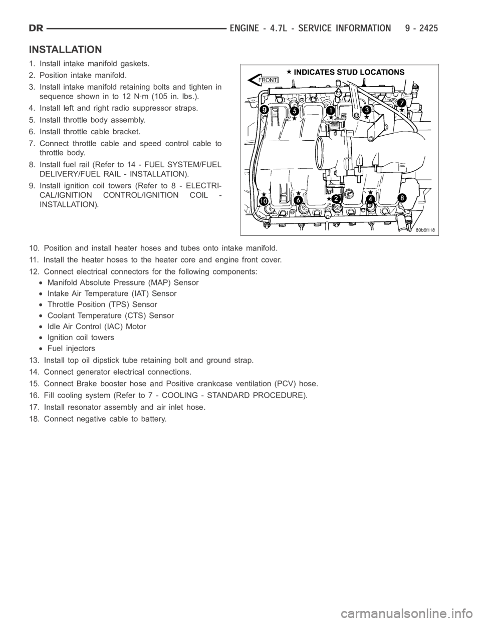
3. Install intake manifold retaining bolts and tighten in
sequence shown in to 12 Nꞏm (105 in. lbs.).
4. Install left and right radio suppressor straps.
5. Install throttle body assembly.
6. Install throttle cable bracket.
7. Connect throttle cable and speed control cable to
throttle body.
8. Install fuel rail (Refer to 14 - FUEL SYSTEM/FUEL
DELIVERY/FUEL RAIL - INSTALLATION).
9. Install ignition coil towers (Refer to 8 - ELECTRI-
CAL/IGNITION CONTROL/IGNITION COIL -
INSTALLATION).
10. Position and install heater hoses and tubes onto intake manifold.
11. Install the heater hoses to the heater core and engine front cover.
12. Connect electrical connectors for the following components:
Manifold Absolute Pressure (MAP) Sensor
Intake Air Temperature (IAT) Sensor
Throttle Position (TPS) Sensor
Coolant Temperature (CTS) Sensor
Idle Air Control (IAC) Motor
Ignition coil towers
Fuel injectors
13. Install top oil dipstick tube retaining bolt and ground strap.
14. Connect generator electrical connections.
15. Connect Brake booster hose and Positive crankcase ventilation (PCV) hose.
16. Fill cooling system (Refer to 7 - COOLING - STANDARD PROCEDURE).
17. Install resonator assembly and air inlet hose.
18. Connect negative cable to battery.
Page 1787 of 5267
ELEMENT - AIR CLEANER
REMOVAL
Filter Element Only
Housing removal is not necessary for element (filter)
replacement.
1. Loosen clamp and disconnect air duct at air
cleaner cover.
2. Pry over 4 spring clips (5) from housing cover (3)
(spring clips retain cover to housing).
3. Release housing cover (3) from locating tabs (4) on
housing and remove cover (3).
4. Remove air cleaner element (filter) from housing.
5. Clean inside of housing before replacing element.
Fig. 1 AIR CLEANER COVER
1-CLAMP
2 - AIR DUCT
3 - AIR CLEANER COVER
4 - LOCATING TABS
5-CLIPS(4)
Page 1788 of 5267
Housing Assembly
1. Loosen clamp and disconnect air duct at air
cleaner cover.
2. Lift entire housing (1) assembly from 4 locating
pins (2).
INSTALLATION
1. Install filter element into housing.
2. Position housing cover into housing locating tabs
(4).
3. Pry up 4 spring clips (5) and lock cover to housing.
4. Install air duct to air cleaner cover and tighten hose
clamp to 3 Nꞏm (30 in. lbs.) torque.
5. If any other hose clamps were removed from air
intake system, tighten them to 3 Nꞏm (30 in. lbs.)
torque.
6. If any bolts were removed from air resonator hous-
ing or air intake tubing, tighten them to 4 Nꞏm (40
in. lbs.) torque.
Fig. 2 AIR CLEANER HOUSING
1 - AIR CLEANER HOUSING ASSEMBLY
2 - LOCATING PINS (4)
Page 1845 of 5267
BEARINGS - CRANKSHAFT MAIN
STANDARD PROCEDURE - CRANKSHAFT MAIN BEARING - FITTING
MAIN BEARING JOURNAL DIAMETER (CRANKSHAFT REMOVED)
Crankshaft removed from the cylinder block.
Clean the oil off the main bearing journal.
Determine the maximum diameter of the journal with a micrometer. Measure at two locations 90° apart at each end
of the journal.
The maximum allowable taper is 0.008mm (0.0004 inch.) and maximum out of round is 0.005mm (0.0002 inch).
Compare the measured diameter with the journal diameter specification (Main Bearing Fitting Chart). Select inserts
required to obtain the specified bearing-to-journal clearance.
CRANKSHAFT MAIN BEARING SELECTION
The main bearings are “select fit” to achieve proper oil clearances. For main bearing selection, the crankshaft coun-
terweight has grade identification marks stamped into it. These marks areread from left to right, corresponding with
journalnumber1,2,3,4and5.
NOTE: Service main bearings are coded. These codes identify what size (grade) the bearing is.
MAIN BEARING SELECTION CHART - 5.7L
GRADE SIZE mm (in.) FOR USE WITH
MARKING JOURNAL SIZE
A0.008 mm U/S 64.988–64.995 mm
(0.0004 in.) U/S (2.5585– 2.5588in.)
BNOMINAL 64.996–65.004 mm
(2.5588–2.5592 in.)
C0.008 mm O/S 65.005–65.012 mm
(0.0004 in.) O/S (2.5592–2.5595 in.)
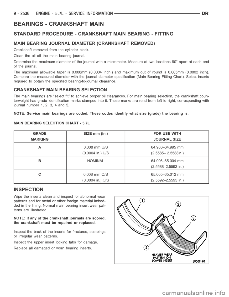
INSPECTION
Wipe the inserts clean and inspect for abnormal wear
patterns and for metal or other foreign material imbed-
ded in the lining. Normal main bearing insert wear pat-
terns are illustrated.
NOTE: If any of the crankshaft journals are scored,
the crankshaft must be repaired or replaced.
Inspect the back of the inserts for fractures, scrapings
or irregular wear patterns.
Inspect the upper insert locking tabs for damage.
Replace all damaged or worn bearing inserts.
Page 1887 of 5267
MANIFOLD - INTAKE
DESCRIPTION
The intake manifold is made of a composite material and features long runners which maximizes low end torque.
The intake manifold uses single plane sealing which consist of eight individual press in place port gaskets to prevent
leaks.
DIAGNOSIS AND TESTING - INTAKE MANIFOLD LEAKAGE
An intake manifold air leak is characterized by lower than normal manifoldvacuum. Also, one or more cylinders may
not be functioning.
WARNING: USE EXTREME CAUTION WHEN THE ENGINE IS OPERATING. DO NOT STAND IN ADIRECT LINE
WITH THE FAN. DO NOT PUT YOUR HANDS NEAR THE PULLEYS, BELTS OR THE FAN. DO NOT WEAR
LOOSE CLOTHING.
1. Start the engine.
2. Spray a small stream of water at the suspected leak area.
3. If a change in RPM is observed the area of the suspected leak has been found.
4. Repair as required.
REMOVAL
1. Disconnect negative cable from battery.
2. Remove resonator assembly and air inlet hose.
3. Disconnect electrical connectors for the following components:
Manifold Absolute Pressure (MAP) Sensor
Intake Air Temperature (IAT) Sensor
Throttle Position (TPS) Sensor
Coolant Temperature (CTS) Sensor
4. Disconnect brake booster hose and positive crankcase ventilation (PCV)hose.
5. Remove generator and set aside.
NOTE: It is not necessary to remove lines or remove freon from A/C compressor.
6. Remove air conditioning compressor and set aside..
7. Bleed fuel system (Refer to 14 - FUEL SYSTEM/FUEL DELIVERY - STANDARD PROCEDURE).
8. Remove intake manifold retaining fasteners in a crisscross pattern starting from the outside bolts and ending at
themiddlebolts.
9. Remove intake manifold and IAFM as an assembly.
CLEANING
NOTE: There is NO approved repair procedure for the intake manifold. If severe damage is found during
inspection, the intake manifold must be replaced.
Before installing the intake manifoldthoroughly clean the mating surfaces. Use a suitable cleaning solvent, then air
dry.