Page 3042 of 5267
42. Install the number 3 thrust washer (1) to the
underdrive shaft assembly (2). Be sure five tabs
are seated properly.
43. Install the number 3 thrust plate (3) to the bottom
of the overdrive shaft assembly (1). Retain with
petrolatum or transmission assembly gel (2).
44. Install the overdrive shaft assembly (1).
Page 3101 of 5267

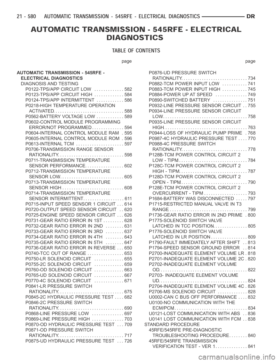
page page
AUTOMATIC TRANSMISSION - 545RFE -
ELECTRICAL DIAGNOSTICS
DIAGNOSIS AND TESTING
P0122-TPS/APP CIRCUIT LOW............. 582
P0123-TPS/APP CIRCUIT HIGH............. 584
P0124-TPS/APP INTERMITTENT ............ 586
P0218-HIGH TEMPERATURE OPERATION
ACTIVATED............................... 588
P0562-BATTERY VOLTAGE LOW ............ 589
P0602-CONTROL MODULE PROGRAMMING
ERROR/NOT PROGRAMMED............... 594
P0604-INTERNAL CONTROL MODULE RAM . 595
P0605-INTERNAL CONTROL MODULE ROM . 596
P0613-INTERNAL TCM ..................... 597
P0706-TRANSMISSION RANGE SENSOR
RATIONALITY............................. 598
P0711-TRANSMISSION TEMPERATURE
SENSOR PERFORMANCE.................. 602
P0712-TRANSMISSION TEMPERATURE
SENSOR LOW............................. 605
P0713-TRANSMISSION TEMPERATURE
SENSOR HIGH............................ 608
P0714-TRANSMISSION TEMPERATURE
SENSOR INTERMITTENT................... 611
P0715-INPUT SPEED SENSOR 1 CIRCUIT . . . 614
P0720-OUTPUT SPEED SENSOR CIRCUIT . . 620
P0725-ENGINE SPEED SENSOR CIRCUIT . . . 626
P0731-GEAR RATIO ERROR IN 1ST ......... 628
P0732-GEAR RATIO ERROR IN 2ND ........ 631
P0733-GEAR RATIO ERROR IN 3RD ........ 637
P0734-GEAR RATIO ERROR IN 4TH ........ 643
P0735-GEAR RATIO ERROR IN 5TH ........ 647
P0736-GEAR RATIO ERROR IN REVERSE . . . 650
P0740-TCC OUT OF RANGE ................ 653
P0750-LR SOLENOID CIRCUIT............. 655
P0755-2C SOLENOID CIRCUIT............. 659
P0760-OD SOLENOID CIRCUIT ............. 663
P0765-UD SOLENOID CIRCUIT ............. 667
P0770-4C SOLENOID CIRCUIT............. 671
P0841-LR PRESSURE SWITCH
RATIONALITY............................. 675
P0845-2C HYDRAULIC PRESSURE TEST .... 682
P0846-2C PRESSURE SWITCH
RATIONALITY............................. 690
P0868-LINE PRESSURE LOW .............. 697
P0869-LINE PRESSURE HIGH .............. 703
P0870-OD HYDRAULIC PRESSURE TEST . . . 709
P0871-OD PRESSURE SWITCH
RATIONALITY............................. 717
P0875-UD HYDRAULIC PRESSURE TEST . . . 726P0876-UD PRESSURE SWITCH
RATIONALITY............................. 734
P0882-TCM POWER INPUT LOW ........... 741
P0883-TCM POWER INPUT HIGH ........... 745
P0884-POWER UPAT SPEED .............. 749
P0890-SWITCHED BATTERY ............... 751
P0932-LINE PRESSURE SENSOR CIRCUIT . . 755
P0934-LINE PRESSURE SENSOR CIRCUIT
LOW...................................... 758
P0935-LINE PRESSURE SENSOR CIRCUIT
HIGH..................................... 763
P0944-LOSS OF HYDRAULIC PUMP PRIME . 768
P0987-4C HYDRAULIC PRESSURE TEST . . . . 770
P0988-4C PRESSURE SWITCH
RATIONALITY............................. 778
P128B-TCM POWER CONTROL CIRCUIT 2
LOW - TIPM............................... 784
P128C-TCM POWER CONTROL CIRCUIT 2
HIGH - TIPM............................... 787
P128D-TCM POWER CONTROL CIRCUIT 2
OPEN - TIPM.............................. 790
P128E-TCM POWER CONTROL CIRCUIT 2
OVERCURRENT - TIPM.................... 793
P1684-BATTERY WAS DISCONNECTED . . . . . 797
P1715-RESTRICTED MANUAL VALVE IN T3
RANGE................................... 799
P1736-GEAR RATIO ERROR IN 2ND PRIME . 800
P1775-SOLENOID SWITCH VALVE
LATCHED IN TCC POSITION................ 805
P1776-SOLENOID SWITCH VALVE
LATCHED IN LR POSITION................. 809
P1790-FAULT IMMEDIATELY AFTER SHIFT . . 813
P1794-SPEED SENSOR GROUND ERROR . . 814
P2700-INADEQUATE ELEMENT VOLUME LR . 818
P2701-INADEQUATE ELEMENT VOLUME 2C . 820
P2702-INADEQUATE ELEMENT VOLUME
OD....................................... 822
P2703- INADEQUATE ELEMENT VOLUME
UD
........................................ 824
P2704-INADEQUATE ELEMENT VOLUME 4C . 826
P2706-MS SOLENOID CIRCUIT............. 828
U0002-CAN C BUS OFF PERFORMANCE . . . . 832
U0100-NO COMMUNICATION WITH THE
ECM/PCM................................. 834
U0121-LOST COMMUNICATION WITH ABS . . 836
U0141 LOST COMMUNICATION WITH FCM . . 838
STANDARD PROCEDURE
45RFE/545RFE PRE-DIAGNOSTIC
TROUBLESHOOTING PROCEDURE......... 840
45RFE/545RFE TRANSMISSION
VERIFICATION TEST - VER 1............... 841
Page 3357 of 5267
U0121-LOST COMMUNICATION WITH ABS
For a complete wiring diagramRefer to Section 8W.
Page 3385 of 5267
19. Install the number 12 thrust bearing (3) over the
output shaft and against the rear planetary gear
set. The flat side of the bearing goes toward the
planetary gearset and the raised tabs on the inner
race should face the rear of the transmission.
20. Install the reverse/input planetary assembly (1)
through the low/reverse clutch assembly.
21. Install the park sprag gear (1) onto the output
shaft.
22. Install the snap-ring (1) to hold the park sprag
onto the output shaft.
Page 3388 of 5267

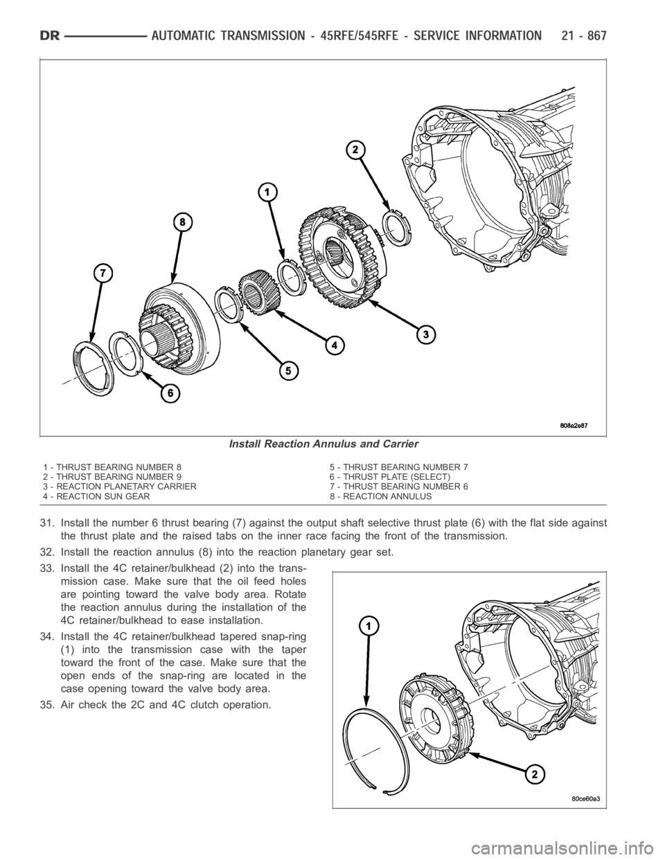
31. Install the number 6 thrust bearing (7) against the output shaft selective thrust plate (6) with the flat side against
the thrust plate and the raised tabs on the inner race facing the front of thetransmission.
32. Install the reaction annulus (8) into the reaction planetary gear set.
33. Install the 4C retainer/bulkhead (2) into the trans-
mission case. Make sure that the oil feed holes
are pointing toward the valve body area. Rotate
the reaction annulus during the installation of the
4C retainer/bulkhead to ease installation.
34. Install the 4C retainer/bulkhead tapered snap-ring
(1) into the transmission case with the taper
toward the front of the case. Make sure that the
open ends of the snap-ring are located in the
case opening toward the valve body area.
35. Air check the 2C and 4C clutch operation.
Install Reaction Annulus and Carrier
1 - THRUST BEARING NUMBER 8 5 - THRUST BEARING NUMBER 7
2 - THRUST BEARING NUMBER 9 6 - THRUST PLATE (SELECT)
3 - REACTION PLANETARY CARRIER 7 - THRUST BEARING NUMBER 6
4 - REACTION SUN GEAR 8 - REACTION ANNULUS
Page 3450 of 5267
18. Install the overdrive clutch pack (13) into the input clutch retainer.The overdrive steel separator plates can be
identified by the lack of the half-moon cuts in the locating tabs.
19. Install the overdrive clutch wavy snap-ring (3) with the two tabbed ears into the input clutch retainer.
20. Install the OD/reverse reaction plate (4) into the input clutch retainer. The reaction plate is non-directional.
21. Install the OD/reverse reaction plate flat snap-ring (6) into the input clutch retainer.
Input Clutch Assembly - Part 2
1 - THRUST BEARING NUMBER 3 10 - SNAP-RING (SELECT)
2 - OD HUB/SHAFT 11 - PLATE
3 - SNAP-RING (WAVE) 12 - DISC
4 - REV/OD REACTION PLATE 13 - OD CLUTCH
5 - THRUST BEARING NUMBER 4 14 - SNAP-RING (TAPERED)
6 - SNAP-RING (FLAT) 15 - UD/OD REACTION PLATE
7 - REVERSE HUB/SHAFT 16 - SNAP-RING (FLAT)
8 - REVERSE CLUTCH 17 - UD HUB/SHAFT
9 - REVERSE REACTION PLATE 18 - THRUST BEARING NUMBER 2
Page 3869 of 5267

OPERATION
Compensation is required for performance variations of two of the input devices. Though the slope of the transfer
functions is tightly controlled, offset may vary due to various environmental factors or manufacturing tolerances.
The pressure transducer is affected by barometric pressure as well as temperature. Calibration of the zero pressure
offset is required to compensate for shifting output due to these factors.
Normal calibration will be performed when sump temperature is above 50 degrees F, or in the absence of sump
temperature data, after the first 10 minutes of vehicle operation. Calibration of the pressure transducer offset occurs
each time the output shaft speed falls below 200 RPM. Calibration shall be repeated each 3 seconds the output
shaft speed is below 200 RPM. A 0.5 second pulse of 95% duty cycle is applied to the governor pressure solenoid
valve and the transducer output is read during this pulse. Averaging of thetransducer signal isnecessary to reject
electrical noise.
Under cold conditions (below 50 degrees F sump), the governor pressure solenoid valve response may be too slow
to guarantee 0 psi during the 0.5 second calibration pulse. Calibration pulses are continued during this period, how-
ever the transducer output valves are discarded. Transducer offset must be read at key-on, under conditions which
promote a stable reading. This value is retained and becomes the offset during the
coldperiod of operation.
GOVERNOR PRESSURE SOLENOID VALVE
The inlet side of the solenoid valve is exposed to normal transmission linepressure. The outlet side of the valve
leads to the valve body governor circuit.
The solenoid valve regulates line pressure to produce governor pressure.Theaveragecurrentsuppliedtothesole-
noid controls governor pressure. One amp current produces zero kPa/psi governor pressure. Zero amps sets the
maximum governor pressure.
The powertrain control module (PCM) turns on the trans control relay whichsupplies electrical power to the solenoid
valve. Operating voltage is 12 volts (DC). The PCM controls the ground sideof the solenoid using the governor
pressure solenoidcontrol circuit.
GOVERNOR PRESSURE SENSOR
The sensor output signal provides the necessary feedback to the PCM. This feedback is needed to adequately
control governor pressure.
GOVERNOR BODY AND TRANSFER PLATE
The transfer plate channels line pressure to the solenoid valve through the governor body. It also channels governor
pressure from the solenoid valve to the governor circuit. It is the solenoid valve that develops the necessary gov-
ernor pressure.
GOVERNOR PRESSURE CURVES
LOW TRANSMISSION FLUID TEMPERATURE
When the transmission fluid is cold the conventional governor can delay shifts, resulting in higher than normal shift
speeds and harsh shifts. The electronically controlled low temperature governor pressure curve is higher than nor-
mal to make the transmission shift at normal speeds and sooner. The PCM usesa temperature sensor in the trans-
mission oil sump to determine when low temperature governor pressure is needed.
NORMAL OPERATION
Normal operation is refined through the increased computing power of the PCM and through access to data on
engine operating conditions provided by the PCM that were not available with the previous stand-alone electronic
module. This facilitated the development of a load adaptive shift strategy - the ability to alter the shift schedule in
response to vehicle load condition. One manifestation of this capabilityis grade
huntingprevention - the ability of
the transmission logic to delay an upshift on a grade if the engine does not have sufficient power to maintain speed
in the higher gear. The 3-2 downshift and the potential for hunting betweengears occurs with a heavily loaded
vehicle or on steep grades. When hunting occurs, it is very objectionable because shifts are frequent and accom-
panied by large changes in noise and acceleration.
Page 3932 of 5267
3. Install rear annulus gear (1) on intermediate shaft
(2).
4. Install thrust washer (2) to rear planetary annulus
gear (1) using petroleum jelly. Be sure washer is
seated against corner witht teh tabs completely in
the locating holes.
5. Install rear planetary gear (2) in rear annulus gear
(1). Be sure planetary carrier is seated against
annulus gear.